Baumer HOG 16 M Montage- Und Betriebsanleitung
Vorschau ausblenden
Andere Handbücher für HOG 16 M:
- Montage- und betriebsanleitung (32 Seiten) ,
- Montage- und betriebsanleitung (32 Seiten) ,
- Montage- und betriebsanleitung (36 Seiten)

Verwandte Anleitungen für Baumer HOG 16 M


Inhaltszusammenfassung für Baumer HOG 16 M
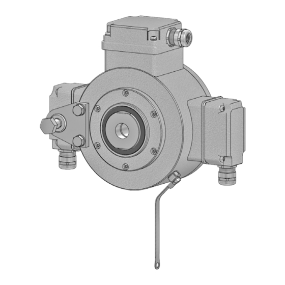
- Seite 1 Montage- und Betriebsanleitung Installation and operating instructions HOG 16 M + DSL Kombination Drehgeber mit integriertem programmierbaren, digitalen Drehzahlschalter - Version mit Gewindebuchse Combination Encoder with integrated programmable, digital speed switch - Version with insert nut...
-
Seite 2: Inhaltsverzeichnis
Allgemeine Hinweise ..............................Sicherheitshinweise ..............................Vorbereitung ..................................Lieferumfang ................................ Lieferumfang Klemmenkasten DSL ......................Lieferumfang Klemmenkasten HOG 16 M .................... Zur Montage erforderlich (nicht im Lieferumfang enthalten) ............Erforderliches Werkzeug (nicht im Lieferumfang enthalten) ............Montage ....................................Schritt 1 ................................... Schritt 2 ................................... - Seite 3 ..................................Scope of delivery ............................... Scope of delivery terminal box DSL ......................Scope of delivery terminal box HOG 16 M ................... Required for mounting (not included in scope of delivery) ............Required tools (not included in scope of delivery) ................
-
Seite 4: Allgemeine Hinweise
Information Empfehlung für die Produkthandhabung Die Kombination HOG 16 M + DSL ist ein opto-elektronisches Prä zi sionsmessgerät, das mit Sorgfalt nur von technisch qualifiziertem Per sonal gehandhabt werden darf. Die zu erwartende Lebensdauer des Gerätes hängt von den Kugellagern ab, die mit einer Dauerschmierung ausgestattet sind. -
Seite 5: General Notes
Information Recommendation for product handling The combination HOG 16 M + DSL is an opto electro nic precision measurement device which must be handled with care by skilled personnel only. The expected operating life of the device depends on the ball bearings, which are equipped with a permanent lubrication. -
Seite 6: Sicherheitshinweise
Sicherheitshinweise Sicherheitshinweise Verletzungsgefahr durch rotierende Wellen Haare und Kleidungsstücke können von rotierenden Wellen erfasst werden. • Vor allen Arbeiten alle Betriebsspannungen ausschalten und Maschinen stillsetzen. Zerstörungsgefahr durch elektrostatische Aufladung Die elektronischen Bauteile in der Kombination sind empfindlich gegen hohe Spannungen. •... -
Seite 7: Security Indications
Security indications Security indications Risk of injury due to rotating shafts Hair and clothes may become tangled in rotating shafts. • Before all work switch off all operating voltages and ensure machinery is stationary. Risk of destruction due to electrostatic charge Electronic parts contained in the combination are sensitive to high voltages. -
Seite 8: Vorbereitung
Erdungsband, Länge ~230 mm Earthing strap, length ~230 mm Klemmenkasten DSL, siehe Abschnitt 3.2. Terminal box DSL, see section 3.2. Klemmenkasten HOG 16 M, Terminal box HOG 16 M, siehe Abschnitt 3.2. see section 3.2. MB163a - 11113956 Baumer_HOG16M-DSL-A_II_DE-EN (16A1) -
Seite 9: Lieferumfang Klemmenkasten Dsl
Connecting board version DSL.E (je nach Bestellung), siehe Abschnitt 6.3. (like precised on order), see section 6.3. Lieferumfang Klemmenkasten HOG 16 M Scope of delivery terminal box HOG 16 M Klemmenkastendeckel Terminal box cover Kombi-Torx-Schraube M4 x 32 mm Screw with torx and slotted drive M4 x 32 mm Kabelverschraubung M20x1,5 Cable gland M20x1.5... -
Seite 10: Zur Montage Erforderlich (Nicht Im Lieferumfang Enthalten)
Vorbereitung / Preparation Zur Montage erforderlich Required for mounting (nicht im Lieferumfang enthalten) (not included in scope of delivery) 3x 3x Drehmomentstütze, als Zubehör erhältlich, Torque arm, available as accessory, Bestellnummer (Länge L, Version): order number (length L, version): 11054922 (155 (-10/+15) mm, Standard) 11054922 (155 (-10/+15) mm, standard) -
Seite 11: Montage
Montage / Mounting Montage Mounting Schritt 1 Step 1 17 mm 19 mm Schritt 2 Step 2 Gewindebuchse leicht lösen. Loosen the insert nut a little. 36 mm TX 20 * Siehe Seite 5 oder 7 See page 5 or 7 MB163a - 11113956 Baumer_HOG16M-DSL-A_II_DE-EN (16A1) ... -
Seite 12: Schritt 3
Montage / Mounting Schritt 3 Step 3 18 mm * Siehe Seite 7 See page 7 Motorwelle einfetten! Lubricate motor shaft! Wir empfehlen, die Kombination so It is recommended to mount the zu montieren, dass der Kabelan- combination with cable connection schluss keinem direkten... -
Seite 13: Schritt 4 - Drehmomentstütze
Montage / Mounting Schritt 4 - Drehmomentstütze Step 4 - Torque arm Die Montage der Drehmomentstütze sollte The torque arm should be mounted spielfrei erfolgen. Ein Spiel von beispiels- free from clearance. A play of just weise ±0,03 mm entspricht einem Rund- ±0.03 mm, results in concentricity lauffehler der Kombination von 0,06 mm, error... -
Seite 14: Hinweis Zur Vermeidung Von Messfehlern
Montage / Mounting Hinweis zur Vermeidung von Messfehlern How to prevent measurement errors Für einen einwandfreien Betrieb der To ensure that the combination operates cor- Kombination ist ein korrekter Anbau, ins- rectly, it is necessary to mount it accurately besondere auch der Drehmomentstütze, as described in section 4.1 to 4.4, which in- notwendig, wie beschrieben in Abschnitt cludes correct mounting of the torque arm. -
Seite 15: Schritt 5
Montage / Mounting Schritt 5 Step 5 45 mm 36 mm Zul. Anzugsmoment Max. tightening torque = 3 Nm 10 * 1.6x8 mm Schritt 6 Step 6 TX 20 Zul. Anzugsmoment Max. tightening torque = 2-3 Nm * Siehe Seite 5 oder 7 See page 5 or 7 MB163a - 11113956 Baumer_HOG16M-DSL-A_II_DE-EN (16A1) -
Seite 16: Abmessung
Abmessung / Dimension Abmessung Dimension (74258, 74264) (74258, 74264) Zubehör Accessory Positive Drehrichtung Positive rotating direction Um 90° versetzt gezeichnet Drawing 90° rotated All dimensions in millimeters (unless otherwise stated) MB163a - 11113956 Baumer_HOG16M-DSL-A_II_DE-EN (16A1) -
Seite 17: Elektrischer Anschluss
Elektrischer Anschluss / Electrical connection Elektrischer Anschluss Electrical connection Klemmenkasten HOG 16 M Klemmenkasten HOG 16 M 6.1.1 Kabelanschluss 6.1.1 Cable connection 6.1.1.1 Schritt 1 6.1.1.1 Step 1 TX 20 TX 20 22 mm 22 mm * Siehe Seite 6... - Seite 18 Elektrischer Anschluss / Electrical connection 6.1.1.2 Schritt 2 6.1.1.2 Step 2 TX 10 6.1.1.3 Schritt 3 6.1.1.3 Step 3 ø5-13 mm * Siehe Seite 6 oder 7 See page 6 or 7 Zur Gewährleistung der angege- To ensure the specified protection benen Schutzart sind nur geeignete of the device the correct cable dia- Kabeldurchmesser zu verwenden.
- Seite 19 6.1.2. 6.1.1.5 Schritt 5 6.1.1.5 Step 5 12e * D-SUB Buchse zum Anschluss an HOG 16 M, TX 10 siehe Abschnitt 6.1.1.6. D-SUB connector (female) for connecting to HOG 16 M, see section 6.1.1.6. 22 mm 12c *...
- Seite 20 Elektrischer Anschluss / Electrical connection 6.1.1.6 Schritt 6 6.1.1.6 Step 6 Zul. Anzugsmoment Max. tightening torque = 2-3 Nm Zul. Anzugsmoment Max. tightening torque = 2-3 Nm TX 20 TX 20 Großer, um 180° wendbarer Klemmenkasten Big terminal box, turn by 180° * Siehe Seite 6 See page 6 Wir empfehlen, die Kombination so...
-
Seite 21: Klemmenbelegung Dn
Elektrischer Anschluss / Electrical connection 6.1.2 Klemmenbelegung 6.1.2 Terminal assignment DN … I, DN … R DN … I, DN … R Max. 1,5 mm Ansicht X Anschlussklemmen, Max. AWG 16 siehe Abschnitt 6.1.1.4. K0 (R-) View X K0 (R+) Connecting terminal, K2 (B-, K2 inv.) see section 6.1.1.4. -
Seite 22: Klemmenkasten Dsl.r
Elektrischer Anschluss / Electrical connection Klemmenkasten DSL.R, Klemmenkasten DSL.R, Version für den Betrieb mit einem ex- version suitable for operation with the ex- ternen Relaismodul DS 93 R (Zubehör) ternal relay module DS 93 R (accessory) 6.2.1 Kabelanschluss 6.2.1 Cable connection 6.2.1.1 Schritt 1 6.2.1.1... - Seite 23 Elektrischer Anschluss / Electrical connection 6.2.1.2 Schritt 2 6.2.1.2 Step 2 Zul. Anzugsmoment Kabelschirm TX 20 Max. tightening torque Cable shield = 2-3 Nm 22 mm ø5-13 mm Ansicht siehe Abschnitt 7.2.2. View see section 7.2.2. Großer, um 180° wendbarer Klemmenkasten Big terminal box, turn by 180°...
-
Seite 24: Klemmenbelegung Dsl.r
Elektrischer Anschluss / Electrical connection 6.2.2 Klemmenbelegung DSL.R 6.2.2 Terminal assignment DSL.R Version mit drei Schaltausgängen, welche Version with 3 switching outputs that can drehzahlabhängig geschaltet werden. Bei be switched according to the speed. If Stillstand des Gerätes oder Drehzahl n the device is at standstill or the rotational kleiner Schaltdrehzahl n ist der jeweilige... -
Seite 25: Blockschaltbild
Elektrischer Anschluss / Electrical connection 6.2.3 Blockschaltbild 6.2.3 Block diagramm Kombination/Combination 15...30 VDC High = 12 V, Low = 0 V HOG 16 M DSL.R 0 V (GND) RS 485 für/for PC/Laptop A, B 0 V (GND) 6.2.4 Ausgangsschaltverhalten 6.2.4... -
Seite 26: Version Ds 93 R Relaismodul (Zubehör)
Elektrischer Anschluss / Electrical connection 6.2.5 Version DS 93 R 6.2.5 Version DS 93 R Relaismodul (Zubehör) relay modul (accessory) 6.2.5.1 Klemmenbelegung 6.2.5.1 Terminal assignment 3 Kontroll-LED‘s Höhe = 55 mm 3 control LEDs Kunststoffgehäuse für Tragschienenmontage (EN 50022) IP 20 3 Relais/relays Height = 55 mm ≤6 A / 250 VAC... -
Seite 27: Klemmenkasten Dsl.e, Version Mit Drei Internen Elektronischen Relais
Elektrischer Anschluss / Electrical connection Klemmenkasten DSL.E, Klemmenkasten DSL.E, Version mit drei internen elektro- version with three internal electronic nischen Relais relays 6.3.1 Kabelanschluss 6.3.1 Cable connection 6.3.1.1 Schritt 1 6.3.1.1 Step 1 TX 20 22 mm 11d * * Siehe Seite 6 See page 6 MB163a - 11113956 Baumer_HOG16M-DSL-A_II_DE-EN (16A1) - Seite 28 Elektrischer Anschluss / Electrical connection 6.3.1.2 Schritt 2 6.3.1.2 Step 2 TX 20 Zul. Anzugsmoment Kabelschirm Max. tightening torque Cable shield = 2-3 Nm 22 mm ø5-13 mm Ansicht siehe Abschnitt 6.3.2. View see section 6.3.2. Um 180° wendbarer Klemmenkasten Terminal box, turn by 180°...
-
Seite 29: Klemmenbelegung Dsl.e
Elektrischer Anschluss / Electrical connection 6.3.2 Klemmenbelegung DSL.E 6.3.2 Terminal assignment DSL.E Integrierte Stromfluss-Überwachung bei Integrated current monitoring for each re- jedem Relais: Messung, ob bei geschlos- lay: This checks whether, when the relay senem Relais ein Strom (mind. 5 mA) is closed, a current of at least 5 mA flows durch den geschalteten Stromkreis fließt. -
Seite 30: Blockschaltbild
Sensorkabel HEK 8 (Zubehör) Sensor cable HEK 8 (accessory) Es wird empfohlen, das Baumer Hübner Baumer Hübner sensor cable HEK 8 is rec- Sensorkabel HEK 8 zu verwenden oder er- ommended. As a substitute a shielded twisted satzweise ein geschirmtes, paarig verseiltes pair cable should be used. -
Seite 31: Demontage
Demontage / Dismounting Demontage Dismounting Schritt 1 Step 1 TX 20 22 mm TX 20 TX 20 TX 10 22 mm * Siehe Seite 5, 6 oder 7 See page 5, 6 or 7 MB163a - 11113956 Baumer_HOG16M-DSL-A_II_DE-EN (16A1) ... - Seite 32 Demontage / Dismounting Schritt 2 Step 2 TX 20 22 mm TX 10 12c * 22 mm TX 20 TX 20 * Siehe Seite 5 oder 6 See page 5 or 6 MB163a - 11113956 Baumer_HOG16M-DSL-A_II_DE-EN (16A1)
- Seite 33 Demontage / Dismounting Schritt 3 Step 3 TX 20 Schritt 4 Step 4 45 mm 36 mm 10 * * Siehe Seite 5 oder 7 See page 5 or 7 MB163a - 11113956 Baumer_HOG16M-DSL-A_II_DE-EN (16A1) ...
- Seite 34 Demontage / Dismounting Schritt 5 Step 5 10 mm Schritt 6 Step 6 * Siehe Seite 7 See page 7 MB163a - 11113956 Baumer_HOG16M-DSL-A_II_DE-EN (16A1)
-
Seite 35: Zubehör
(DSL.R version only) 3 x Umschalter 3 x Change-over switch (≤6 A/250 VAC; ≤1 A/48 VDC) (≤6 A/250 VAC; ≤1 A/48 VDC) für HOG 16 M for HOG 16 M • Sensorkabel für Drehgeber • Sensor cable for encoders HEK 8 HEK 8 •... -
Seite 36: Technische Daten
• Abtastprinzip: Optisch • Störfestigkeit: EN 61000-6-2:2005 • Störaussendung: EN 61000-6-3:2007/A1:2011 • Zulassung: HOG 16 M + DSL.E • Betriebsspannung: 9...30 VDC HOG 16 M + DSL.R • Betriebsspannung: 15...30 VDC Technische Daten - elektrisch (Drehgeber) • Impulse pro Umdrehung: 512...2500 (Je nach Bestellung) -
Seite 37: Technische Daten - Mechanisch
Technische Daten - mechanisch • Baugröße (Flansch): ø158 mm • Wellenart: ø20...50 mm (durchgehende Hohlwelle) • Zulässige Wellenbelastung: ≤450 N axial ≤600 N radial • Schutzart DIN EN 60529: IP66 • Drehzahl (n): ≤6.000 U/min (mechanisch) • Schaltdrehzahlbereich (n Impulszahl = 512: ±16...6000 U/min Impulszahl = 1024: ±8...6000 U/min Impulszahl = 2048: ±4...3500 U/min... -
Seite 38: Technical Data
Technical data Technical data Technical data - electrical ratings • Consumption w/o load: ≤200 mA • Sensing method: Optical • Interference immunity: EN 61000-6-2:2005 • Emitted interference: EN 61000-6-3:2007/A1:2011 • Approval: HOG 16 + DSL.E • Voltage supply: 9...30 VDC HOG 16 + DSL.R •... -
Seite 39: Technical Data - Mechanical Design
Technical data - mechanical design • Size (flange): ø158 mm • Shaft type: ø20...50 mm (through hollow shaft) • Shaft loading: ≤450 N axial ≤600 N radial • Protection DIN EN 60529: IP66 • Speed (n): ≤6000 rpm • Range of switching speed (n Pulses = 512: ±16...6000 rpm Pulses = 1024: ±8...6000 rpm... - Seite 40 Baumer Hübner GmbH P.O. Box 12 69 43 · 10609 Berlin, Germany Phone: +49 (0)30/69003-0 · Fax: +49 (0)30/69003-104 info@baumerhuebner.com · www.baumer.com/motion Version: 74258, 74264 MB163a - 11113956 Baumer_HOG16M-DSL-A_II_DE-EN (16A1 - 06.04.2016)