Baumer HOG 86 + FSL Montage- Und Betriebsanleitung

Verwandte Anleitungen für Baumer HOG 86 + FSL


Inhaltszusammenfassung für Baumer HOG 86 + FSL
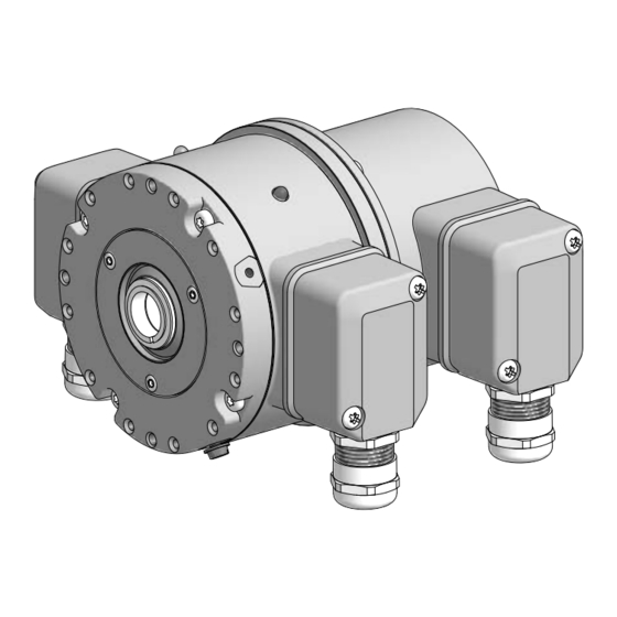
- Seite 1 Montage- und Betriebsanleitung Mounting and operating instructions Option M: redundant + Option EMS: LED Option EMS: LED HOG 86 + FSL Kombination Inkrementaler Drehgeber mit integriertem mechanischen Fliehkraftschalter Combination Incremental encoder with integrated mechanical centrifugal switch...
- Seite 2 Inhaltsverzeichnis Inhaltsverzeichnis Elektrischer Anschluss ........Allgemeine Hinweise ..........HOG 86 ..............Sicherheitshinweise ..........6.1.1 Montage Anschlusskabel ......Vorbereitung ..............6.1.2 Beschreibung der Anschlüsse ....Lieferumfang .............. 6.1.3 Ausgangssignale .......... Zur Montage erforderlich 6.1.4 Anschlussbelegung ........(nicht im Lieferumfang enthalten) ....6.1.4.1 Standard ...........
-
Seite 3: Inhaltsverzeichnis
Table of contents Table of contents Electrical connection ..........General notes ..............HOG 86 ..............Security indications ........... 6.1.1 Mounting connecting cable ..... Preparation ..............6.1.2 Terminal significance ........Scope of delivery ............. 6.1.3 Output signals ..........Required for mounting 6.1.4 Terminal assignment ........ -
Seite 4: Allgemeine Hinweise
Hinweis zur Gewährleistung eines einwandfreien Betriebes des Gerätes Information Empfehlung für die Gerätehandhabung Die Kombination HOG 86 + FSL ist ein opto-elektronisches Prä zi sionsmessgerät und ein mechanisch wirkendes Schaltgerät, das mit Sorgfalt nur von technisch qualifiziertem Per sonal gehandhabt werden darf. -
Seite 5: General Notes
Informations to ensure correct device operation Information Recommendation for device handling The combination HOG 86 + FSL is an opto electro nic precision measurement device and a mechanically operated switching device which must be handled with care by skilled person- nel only. -
Seite 6: Sicherheitshinweise
Sicherheitshinweise Sicherheitshinweise Verletzungsgefahr durch rotierende Wellen Haare und Kleidungsstücke können von rotierenden Wellen erfasst werden. • Vor allen Arbeiten alle Betriebsspannungen ausschalten und Maschinen stillsetzen. Zerstörungsgefahr durch elektrostatische Aufladung Die elektronischen Bauteile im Gerät sind empfindlich gegen hohe Spannungen. • Steckkontakte und elektronische Komponenten nicht berühren. •... -
Seite 7: Security Indications
Security indications Security indications Risk of injury due to rotating shafts Hair and clothes may become tangled in rotating shafts. • Before all work switch off all voltage supplies and ensure machinery is stationary. Risk of destruction due to electrostatic charge Electronic parts contained in the device are sensitive to high voltages. -
Seite 8: Vorbereitung
Vorbereitung / Preparation Vorbereitung Preparation Lieferumfang Scope of delivery 10a 10b Gehäuse HOG 86 Housing HOG 86 Abdeckung FSL Cover FSL Einseitig offene Hohlwelle oder Konuswelle Blind hollow shaft or cone shaft with spanner mit Schlüsselfläche SW 13 mm flat 13 mm a/f Spannelement Clamping element (nur bei einseitig offener Hohlwelle) -
Seite 9: Required For Mounting (Not Included In Scope Of Delivery)
Vorbereitung / Preparation Zur Montage erforderlich Required for mounting (nicht im Lieferumfang enthalten) (not included in scope of delivery) Montageset Erdungsband als Zubehör erhältlich: Mounting kit earthing strap available as ac- Bestellnummer 11071906, bestehend aus ... cessory: Order number 11071906, including ... Erdungsband, Länge ~230 mm Earthing strap, length ~230 mm Zylinderschraube M6x8 mm, ISO 1207... -
Seite 10: Attachements For Torque Arm (Not Included In Scope Of Delivery)
Vorbereitung / Preparation Befestigungen für Drehmomentstütze Attachements for torque arm (nicht im Lieferumfang enthalten) (not included in scope of delivery) 17e 17c 18e 18c Stützblech-Montageset R63 für Drehmoment- Support plate mounting kit R63 for torque arm stütze Größe M6, als Zubehör erhältlich: size M6, available as accessory: Bestellnummer 11071850, bestehend aus ... -
Seite 11: Required For Dismounting (Not Included In Scope Of Delivery)
Vorbereitung / Preparation Zur Demontage erforderlich Required for dismounting (nicht im Lieferumfang enthalten) (not included in scope of delivery) Montage-/Demontageset als Zubehör erhält- Mounting/dismounting kit available as acces- lich: sory: Bestellnummer 11077087, bestehend aus ... Order number 11077087, including ... Gewindestift M6x10 mm, ISO 7436 Setscrew M6x10 mm, ISO 7436 Zylinderschraube M8x45 mm, ISO 4762... -
Seite 12: Mounting
Montage / Mounting Montage Mounting In den Bildern am Beispiel vom HOG 86 Pictures showing the HOG 86 + FSL as + FSL. Gleiche Montageschritte bei den example. Same mounting steps for all anderen Versionen, wenn nicht anders other versions, unless otherwise stated. -
Seite 13: Direct Mounting
Montage / Mounting 4.1.1 Mit Stützblech 4.1.1 With support plate 4.1.1.2 Schritt 2 4.1.1.2 Step 2 10 mm Variante 2: 10 mm Variante 1: 4.1.2 Direkte Montage 4.1.2 Direct mounting Montagebeispiel 1 (4 Positionen möglich) Mounting example 1 (4 different positions) 4 mm Montagebeispiel 2 Mounting example 2... -
Seite 14: Mounting Of The Earthing Strap (Accessory)
Montage / Mounting Montage des Erdungsbandes Mounting of the earthing strap (Zubehör) (accessory) Variante 1: Variante 2: 1.6x8 mm Montage an Antriebswelle Mounting to drive shaft 4.3.1 Schritt 1 4.3.1 Schritt 1 TX 20 * Siehe Seite 5 oder 6 See page 5 or 6 MB194.1 - 11138089 Baumer_HOG86-FSL_II_DE-EN (18A1) -
Seite 15: Blind Hollow Shaft
Montage / Mounting 4.3.2 Schritt 2 4.3.2 Step 2 4.3.2.1 Einseitig offene Hohlwelle 4.3.2.1 Blind hollow shaft Zentrierbohrung Center hole DIN 332-D, M6x16 mm 13 mm 5 mm ø16 13b 13a Zul. Anzugsmoment: Max. tightening torque: = 6 Nm 53 mm 52 mm (40...52 mm) ø16 16 mm... -
Seite 16: Cone Shaft
Montage / Mounting 4.3.2 Schritt 2 4.3.2 Step 2 4.3.2.2 Konuswelle 4.3.2.2 Cone shaft Zentrierbohrung Center hole DIN 332-D, M6x16 mm 13 mm 5 mm 1:10 Zul. Anzugsmoment: Max. tightening torque: = 3...4 Nm * Siehe Seite 6 See page 6 Antriebswelle einfetten. -
Seite 17: Mounting With Support Plate
Montage / Mounting 4.3.3 Schritt 3 4.3.3 Step 3 4.3.3.1 Montage mit Stützblech 4.3.3.1 Mounting with support plate 10 mm 1.6x8 mm 4.3.3.2 Direkte Montage 4.3.3.2 Direct mounting 10 mm * Siehe Seite 6 oder 7 See page 6 or 7 MB194.1 - 11138089 Baumer_HOG86-FSL_II_DE-EN (18A1) -
Seite 18: Mounting With Support Plate
Montage / Mounting 4.3.4 Schritt 4 4.3.4 Step 4 4.3.4.1 Montage mit Stützblech 4.3.4.1 Mounting with support plate Die Montage der Drehmomentstütze The torque arm should be mounted sollte spielfrei erfolgen. Ein Spiel von free from clearance. A play of just beispielsweise ±0,03 mm entspricht ±0.03 mm, results in a runout of the einem Rundlauffehler des Gerätes von... -
Seite 19: Direct Mounting
Montage / Mounting 4.3.4 Schritt 4 4.3.4 Step 4 4.3.4.2 Direkte Montage 4.3.4.2 Direct mounting L2 (≥L1) Die Montage der Drehmomentstütze The torque arm should be mounted sollte spielfrei erfolgen. Ein Spiel von free from clearance. A play of just beispielsweise ±0,03 mm entspricht ±0.03 mm, results in a runout of the einem Rundlauffehler des Gerätes von... -
Seite 20: How To Prevent Measurement Errors
Montage / Mounting 4.3.5 Hinweis zur Vermeidung von Messfeh- 4.3.5 How to prevent measurement errors lern Für einen einwandfreien Betrieb des To ensure that the device operates cor- Gerätes ist eine korrekte Montage, ins- rectly, it is necessary to mount it ac- besondere auch der Drehmomentstütze, curately as described in section 4.1 and notwendig, wie beschrieben in Abschnitt... - Seite 21 Montage / Mounting 4.3.6 Schritt 5 4.3.6 Step 5 Zul. Anzugsmoment Max. tightening torque = 2...3 Nm TX 20 Ansicht D View D Ansicht D Schieberstellung View D Slider position * Siehe Seite 5 See page 5 Wir empfehlen, das Gerät so zu It is recommended to mount the device montieren, dass der Kabelanschluss with cable connection facing down-...
-
Seite 22: Abmessungen
Abmessungen / Dimensions Abmessungen Dimensions Einseitig offene Hohlwelle 5.1. Blind hollow shaft (73438, 73450, 73451, 73452) (73438, 73450, 73451, 73452) Positive Drehrichtung Positive rotating direction LED* Option M: redundant Konuswelle Cone shaft Positive Drehrichtung Positive rotating direction LED* Option M: redundant Alle Abmessungen in Millimeter (wenn nicht anders angegeben) Option EMS... -
Seite 23: Mounting Possibilities
Abmessungen / Dimensions Montagemöglichkeiten Mounting possibilities Stützbleche (Zubehör) Support plates (accessories) Alle Abmessungen in Millimeter (wenn nicht anders angegeben) * Siehe Seite 8 oder 9 All dimensions in millimeters (unless otherwise stated) See page 8 or 9 MB194.1 - 11138089 Baumer_HOG86-FSL_II_DE-EN (18A1) -
Seite 24: Electrical Connection
Elektrischer Anschluss / Electrical connection Elektrischer Anschluss Electrical connection HOG 86 HOG 86 6.1.1 Montage Anschlusskabel 6.1.1 Mounting connecting cable TX 20 10c * 22 mm Zul. Anzugsmoment Max. tightening torque Kabelschirm = 2...3 Nm Cable shield 10d * Ansicht X siehe Abschnitt 6.1.4. -
Seite 25: Terminal Significance
Elektrischer Anschluss / Electrical connection 6.1.2 Beschreibung der Anschlüsse 6.1.2 Terminal significance Betriebsspannung +UB; + Voltage supply Masseanschluss ; ; GND; 0V Ground Erdungsanschluss (Gehäuse) Earth ground (housing) Ausgangssignal Kanal 1 K1; A; A+ Output signal channel 1 Ausgangssignal Kanal 1 invertiert K1;... -
Seite 26: Terminal Assignment
Elektrischer Anschluss / Electrical connection 6.1.4 Anschlussbelegung 6.1.4 Terminal assignment 6.1.4.1 Standard 6.1.4.1 Standard Ansicht X Anschlussklemmen, siehe Abschnitt 6.1.1. View X Connecting terminal, see section 6.1.1. Max. 1,5 mm Max. AWG 16 Zwischen besteht keine Verbindung. There is no connection between 6.1.4.2 Option EMS 6.1.4.2... -
Seite 27: System
Elektrischer Anschluss / Electrical connection 6.1.5 Option EMS (Enhanced Monitoring 6.1.5 Option EMS (Enhanced Monitoring System): Status LED / Fehlerausgang System): Status LED / Error output Rotblinkend Flash light red Signalfolge-, Nullimpuls- oder Impulszahl- Error of signal sequence, zero pulse or fehler pulses (Fehlerausgang = HIGH-LOW-Wechsel) -
Seite 28: 6.1.6 Sensor Cable Hek 8 (Accessory)
Sensorkabel HEK 8 (Zubehör) 6.1.6 Sensor cable HEK 8 (accessory) Es wird empfohlen, das Baumer Hübner Baumer Hübner sensor cable HEK 8 is Sensorkabel HEK 8 zu verwenden oder recommended. As a substitute a shielded ersatzweise ein geschirmtes, paarig ver- twisted pair cable should be used. -
Seite 29: Fsl
Elektrischer Anschluss / Electrical connection 6.2.1 Montage Anschlusskabel 6.2.1 Mounting connecting cable TX 20 22 mm 11d * Ansicht Y siehe Abschnitt 6.2.2. View Y see section 6.2.2. Zul. Anzugsmoment Max. tightening torque = 2...3 Nm * Siehe Seite 5 oder 6 ø7...12 mm See page 5 or 6 Zur Gewährleistung der angegebenen... -
Seite 30: Dismounting
Demontage / Dismounting Demontage Dismounting In den Bildern am Beispiel vom HOG 86 + Pictures showing the HOG 86 + FSL as FSL. Gleiche Demontageschritte bei den example. Same dismounting steps for all anderen Versionen, wenn nicht anders other versions, unless otherwise stated. - Seite 31 Demontage / Dismounting Schritt 2 Step 2 TX 20 10d * 10c * 22 mm Schritt 3 Step 3 TX 20 * Siehe Seite 5 oder 6 See page 5 or 6 MB194.1 - 11138089 Baumer_HOG86-FSL_II_DE-EN (18A1)
- Seite 32 Demontage / Dismounting Schritt 4 Step 4 10 mm 1.6x8 mm Schritt 5 Step 5 13 mm 5 mm * Siehe Seite 6 oder 7 See page 6 or 7 MB194.1 - 11138089 Baumer_HOG86-FSL_II_DE-EN (18A1)
- Seite 33 Demontage / Dismounting Schritt 6 Step 6 0.8x4 mm Schritt 7 Step 7 17 mm 6 mm Schritt 8 Step 8 * Siehe Seite 8 See page 8 MB194.1 - 11138089 Baumer_HOG86-FSL_II_DE-EN (18A1)
-
Seite 34: Technische Daten
Technische Daten Technische Daten Technische Daten - elektrisch • Störfestigkeit: EN 61000-6-2 • Störaussendung: EN 61000-6-3 • Zulassung: Technische Daten - elektrisch (Drehgeber) • Betriebsspannung: 9...30 VDC (HTLP, TTL Version R) 5 VDC ±5 % (TTL) • Betriebsstrom ohne Last: ≤100 mA •... -
Seite 35: Technische Daten - Mechanisch
Technische Daten - mechanisch • Baugröße (Flansch): ø105 mm • Wellenart: ø16 mm (einseitig offene Hohlwelle) ø17 mm (Konuswelle 1:10) • Zulässige Wellenbelastung: ≤350 N axial ≤450 N radial • Schutzart DIN EN 60529: IP66 • Drehzahl (n): ≤1,25 · ns •... -
Seite 36: 13 8.1 Technical Data - Electrical Ratings
Technical data Technical data Technical data - electrical ratings • Interference immunity: EN 61000-6-2 • Emitted interference: EN 61000-6-3 • Approval: Technical data - electrical ratings (encoder) • Voltage supply: 9...30 VDC* (HTL-P, TTL - version R) 5 VDC ±5 % (TTL) •... -
Seite 37: 15 8.4 Technical Data - Mechanical Design
Technical data - mechanical design • Size (flange): ø105 mm • Shaft type: ø16 mm (blind hollow shaft) ø17 mm (cone shaft 1:10) • Admitted shaft load: ≤350 N axial ≤450 N radial • Protection DIN EN 60529: IP66 • Speed (n): ≤1.25 · ns • Range of switching speed (ns): 850...4500 rpm (Δn = 2 rpm/s) (as ordered) • Operating torque: 6 Ncm •... -
Seite 38: Accessories
Zubehör / Accessories Zubehör Accessories • Drehmomentstütze Größe M6: • Torque arm size M6: Bestellnummer siehe Order number see Abschnitt 4.2 section 4.2 • Montageset für • Mounting kit for Drehmomentstütze Größe M6: torque arm size M6: Bestellnummer 11071904 Order number 11071904 •... - Seite 39 MB194.1 - 11138089 Baumer_HOG86-FSL_II_DE-EN (18A1)
- Seite 40 Baumer Hübner GmbH P.O. Box 12 69 43 · 10609 Berlin, Germany Phone: +49 (0)30/69003-0 · Fax: +49 (0)30/69003-104 info@baumerhuebner.com · www.baumer.com/motion Version: 73438, 73450, 73451, 73452 MB194.1 - 11138089 Baumer_HOG86-FSL_II_DE-EN (18A1-17.10.2018)