Fronius Ohmpilot Bedienungsanleitung
Vorschau ausblenden
Andere Handbücher für Ohmpilot:
- Bedienungsanleitung (200 Seiten) ,
- Schnellstartanleitung (8 Seiten) ,
- Bedienungsanleitung (60 Seiten)
Inhaltsverzeichnis
Verfügbare Sprachen
Verfügbare Sprachen
/ Perfect Charging / Perfect Welding /
[
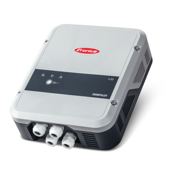
Fronius Ohmpilot
Fronius prints on elemental chlorine free paper (ECF) sourced from certified sustainable forests (FSC).
Solar Energy
42,0410,2141
001-16042020
Bedienungsanleitung
Balance of System
Operating Instructions
Balance of System
Istruzioni per l'uso disponibili
online su:
http://www.fronius.com
[
Kapitel
Inhaltsverzeichnis

Verwandte Anleitungen für Fronius Ohmpilot


Inhaltszusammenfassung für Fronius Ohmpilot
- Seite 1 / Perfect Charging / Perfect Welding / Bedienungsanleitung Fronius Ohmpilot Balance of System Operating Instructions Balance of System Istruzioni per l’uso disponibili online su: http://www.fronius.com 42,0410,2141 001-16042020 Fronius prints on elemental chlorine free paper (ECF) sourced from certified sustainable forests (FSC).
-
Seite 3: Inhaltsverzeichnis
Standort-Wahl ............................Symbolerklärung - Montagelage ......................Wandmontage............................Sicherheit .............................. Auswahl von Dübel und Schrauben...................... Schrauben Empfehlung ........................Ohmpilot an der Wand montieren ......................Installation..............................Abisolierlängen ............................. Elektrischer Anschluss.......................... 1-phasiger Heizstab bis 3 kW ........................Anwendungsbeispiel 1 .......................... 3-phasiger Heizstab 900 W bis 9 kW...................... - Seite 4 Manuelle Einstellungen HEIZUNG 1..................... Legionellenschutz aktivieren......................... Tagesverlauf anpassen......................... Temperaturbegrenzung ........................Anhang Statusmeldungen ............................Statusmeldungen ..........................Technische Daten ............................Eingangsdaten ............................Schnittstellen............................Ausgangsdaten ............................. Allgemeine Daten..........................Prüfungen / Angaben ..........................Prüfungen/Angaben ..........................Garantiebedingungen und Entsorgung ...................... Fronius Werksgarantie.......................... Entsorgung............................Berücksichtigte Normen und Richtlinien ....................
-
Seite 5: Sicherheitsvorschriften
Sicherheitsvorschriften Erklärung Sicher- GEFAHR! heitshinweise Bezeichnet eine unmittelbar drohende Gefahr. ► Wenn sie nicht gemieden wird, sind Tod oder schwerste Verletzungen die Folge. WARNUNG! Bezeichnet eine möglicherweise gefährliche Situation. ► Wenn sie nicht gemieden wird, können Tod und schwerste Verletzungen die Folge sein. -
Seite 6: Umgebungsbedingungen
Nicht voll funktionstüchtige Sicherheitseinrichtungen vor dem Einschalten des Gerätes von einem autorisierten Fachbetrieb instandsetzen lassen. Schutzeinrichtungen niemals umgehen oder außer Betrieb setzen. Die Positionen der Sicherheits- und Gefahrenhinweise am Gerät, entnehmen Sie dem Ka- pitel „Allgemeines“ der Bedienungsanleitung Ihres Gerätes. Störungen, die die Sicherheit beeinträchtigen können, vor dem Einschalten des Gerätes beseitigen. -
Seite 7: Datensicherheit
Datensicherheit Für die Datensicherung von Änderungen gegenüber den Werkseinstellungen ist der An- wender verantwortlich. Im Falle gelöschter persönlicher Einstellungen haftet der Hersteller nicht. Urheberrecht Das Urheberrecht an dieser Bedienungsanleitung verbleibt beim Hersteller. Text und Abbildungen entsprechen dem technischen Stand bei Drucklegung. Änderungen vorbehalten. -
Seite 9: Allgemeine Informationen
Allgemeine Informationen... -
Seite 11: Allgemeines
PV-Anlage mittels Pulsweitenmodulation stufenlos für eine Phase zwischen 0 und 100% (bzw. 0 und 3 kW) regeln kann. Darüber hinaus verfügt der Ohmpilot über 2 zusätz- liche Ausgänge zum Schalten weiterer Phasen. Dadurch können Heizstäbe mit einer Leis- tung von 300 W bis 9 kW stufenlos geregelt werden. -
Seite 12: Leistungsbereich
Phase 1 stufenlos geregelt. Steht darüber hinaus noch mehr Leistung zur Verfügung, schaltet der Ohmpilot Phase 2 dazu und Phase 1 kann erneut zwischen 3 – 6 kW stufenlos regeln. Ist die verfügbare Leistung höher als 6 kW, so schaltet der Ohmpilot Phase 3 dazu und Phase 1 regelt wieder zwischen 6 und 9 kW stufenlos. - Seite 13 Sicherheitssymbole: Gefahr von schwerwiegenden Personen- und Sachschäden durch Fehlbedie- nung Beschriebene Funktionen erst anwenden, wenn folgende Dokumente vollständig gelesen und verstanden wurden: diese Bedienungsanleitung sämtliche Bedienungsanleitungen der Systemkomponenten der Photovolta- ikanlage, insbesondere Sicherheitsvorschriften Gefährliche elektrische Spannung Vor dem Öffnen des Geräts, Entladezeit der Kondensatoren abwarten! Heiße Oberfläche Text der Warnhinweise: WARNUNG!
-
Seite 14: Fronius Smart Meter
Fronius Smart Meter Fronius Smart Für den Betrieb des Ohmpilots ist ein Fronius Smart Meter notwendig, sodass die Über- Meter einbinden schussenergie gemessen werden kann. Für die Einbindung des Fronius Smart Meter ist ein Wechselrichter mit Datamanager 2.0 oder höher ab V3.8.1-x bzw. eine Datamanager Box ab V3.8.1-x notwendig. -
Seite 16: Bedienelemente Und Anschlüsse
Ohmpilot das WLAN Passwort übermittelt. WLAN Access Point wird für 30 Minuten 2x drücken aktiviert, sodass über die Fronius Solar Web App Einstellungen am Ohmpilot vor- genommen werden können. 3x drücken Boostmode - Dimmerstufe wird für 4 Stun- den mit 100% angesteuert, L2 und L3 wird durchgeschalten. -
Seite 17: Anschlussbereich
Anschlussbe- reich LED grün LED blau LED rot Taster Ethernet RJ45 mind. CAT5, geschirmt Modbus RTU (Defaultadresse 40) Federzug 0,2 - 1,5 mm , max. 1000m, geschirmt und verdrillt Anschluss Klemme Temperatursensor PT 1000, Federzug 0,2 - 1,5 mm EINGANG - Zuleitung Netz 1x 230 V, oder 3x 230 V, Federzug 1,5 - 2,5 mm AUSGANG - Heizstab L2 Federzug 1,5 - 2,5 mm... - Seite 18 (11) Multifunktions-Relaisausgang, (siehe Anwendungsbeispiele) regelbar max. 13 A ohmsche Last, Federzug 1,5 - 2,5 mm WARNUNG! Gefährliche Spannungen. Ein Draht löst sich und berührt gefährliche Spannungen. ► Werden Signalkabel angeschlossen, müssen die einzelnen Drähte unmittelbar vor der Klemme mit einem Kabelbinder zusammengebunden werden. (12) AUSGANG - Heizstab stufenlos bis 3 kW...
-
Seite 19: Auswahl Der Heizung
Ein mechanischer Temperaturschalter ver- einfacht die Inbetriebnahme und die Nut- zung. Falls kein mechanischer Temperaturschalter zur Verfügung steht, kann am Ohmpilot auch ein Temperatur- sensor angeschlossen werden, welcher die maximale Temperatur begrenzt. (siehe Ka- pitel „Temperaturbegrenzung“ auf Seite 56 ) Beispiel für die... -
Seite 21: Installation Und Inbetriebnahme
Installation und Inbetriebnahme... -
Seite 23: Standort-Wahl Und Montagelage
Der Ohmpilot entspricht Schutzart IP 54 und ist gegen allseitiges Spritz- wasser geschützt. Um die Erwärmung des Ohmpilot so gering wie möglich zu halten, den Ohmpilot keiner direkten Sonneneinstrahlung aussetzen. Den Ohmpilot an einer geschützten Position montieren. Der Ohmpilot darf nur bei einer Umgebungstemperatur von 0-40°C montiert und betrieben werden. -
Seite 24: Symbolerklärung - Montagelage
Lager- und Verarbeitungsräumen für Obst, Gemüse und Weinbau- produkte Räumen für die Aufbereitung von Körnern, Grünfutter und Futter- mitteln Symbolerklärung Der Ohmpilot ist für die senkrechte Montage an einer senkrechten Wand - Montagelage geeignet. Den Ohmpilot nicht horizontal montieren. Den Ohmpilot nicht auf einer schrägen Fläche montieren. - Seite 25 Den Ohmpilot nicht in Horizontallage an einer senkrechten Wand mon- tieren. Den Ohmpilot nicht überhängend mit den Anschlüssen nach oben mon- tieren. Den Ohmpilot nicht überhängend mit den Anschlüssen nach oben mon- tieren. Den Ohmpilot nicht überhängend mit den Anschlüssen nach unten mon- tieren.
-
Seite 26: Wandmontage
Ohmpilots erforderlich. Das Befestigungsmaterial ist daher nicht im Lieferumfang des Ohmpilots enthalten. Der Monteur ist für die richtige Auswahl des Befestigungsmaterials selbst verantwortlich. Der Ohmpilot muss mit vier Schrauben montiert werden. Stellen Sie sicher, dass die Schrauben fest sitzen und die Wand tragfähig ist. -
Seite 27: Ohmpilot An Der Wand Montieren
Ohmpilot an der Wand montieren... -
Seite 28: Installation
WICHTIG! Die maximale Leitungslänge vom Ausgang des Ohmpilot zum Verbraucher (Heizstab) darf aus EMV Gründen 5m nicht überschreiten. WICHTIG! Der Ohmpilot muss vor Überspannung aus dem Netz geschützt werden. WICHTIG! Bei Anschluss eines Heizstabes die Erdung des Boilers/Puffers sowie der Heiz- anlage prüfen. -
Seite 29: 1-Phasiger Heizstab Bis 3 Kw
1-phasiger Heizstab bis 3 kW Anwendungsbei- spiel 1 EINGANG - Zuleitung von Netz 1x 230V, Federzug 1,5 - 2,5 mm² AUSGANG bis 3 kW regelbar, max. 13A ohmsche Last, Federzug 1,5 - 2,5 mm² Warmwasser Boiler Temperatursensor PT1000 Fremdquelle (z.B. Gastherme) Heizstab (max. -
Seite 30: Optionale Einstellungen
WICHTIG! Plug & Play - Bei dieser Anwendung sind nach erfolgreicher Verbindung zum Wechselrichter keine weiteren Einstellungen notwendig. Der Fronius Smart Meter erfasst am Einspeisepunkt die aktuelle Leistung und überträgt die Daten an den Datamanager. Der Datamanger regelt durch Ansteuerung des Ohmpilot eine zur Verfügung stehende Überschussenergie auf Null aus. -
Seite 31: 3-Phasiger Heizstab 900 W Bis 9 Kw
3-phasiger Heizstab 900 W bis 9 kW Anwendungsbei- spiel 2 EINGANG - Zuleitung Netz 3x 230 V, Federzug 1,5 - 2,5 mm² AUSGANG - Heizstab L2 AUSGANG - Heizstab L3 AUSGANG bis 3 kW regelbar, max. 13 A, ohmsche Last, Federzug 1,5 - 2,5 mm² Warmwasser Boiler Temperatursensor PT1000 Fremdquelle (z.B. - Seite 32 WICHTIG! Plug & Play - Bei dieser Anwendung sind nach erfolgreicher Verbindung zum Wechselrichter keine weiteren Einstellungen notwendig. Der Fronius Smart Meter erfasst am Einspeisepunkt die aktuelle Leistung und überträgt die Daten an den Datamanager. Der Datamanger regelt durch Ansteuerung des Ohmpilot eine zur Verfügung stehende Überschussenergie auf Null aus.
-
Seite 33: 1-Phasiger Heizstab Bis 3 Kw Mit Wärmepumpen-Ansteuerung
1-phasiger Heizstab bis 3 kW mit Wärmepumpen-An- steuerung Anwendungsbei- spiel 3 EINGANG - Zuleitung Netz 1x 230 V, Federzug 1,5 - 2,5 mm² Multifunktions-Relaisausgang WARNUNG! Gefährliche Spannungen. Ein Draht löst sich und berührt gefährliche Spannungen. ► Werden Signalkabel angeschlossen, müssen die einzelnen Drähte unmittelbar vor der Klemme mit einem Kabelbinder zusammengebunden werden. - Seite 34 Ferrit (im Lieferumfang) (10) Der Fronius Smart Meter erfasst am Einspeisepunkt die aktuelle Leistung und überträgt die Daten an den Datamanager. Der Datamanager regelt durch Ansteuerung des Ohmpilot eine zur Verfügung stehende Überschussenergie auf Null aus. Dies geschieht im Detail durch stufenlose Ansteuerung des angeschlossenen Heizstabes am Ohmpilot und durch gezieltes Zuschalten der Wärmepumpe.
-
Seite 35: Einstellungen Im Menübereich
Einstellungen im Menübereich Website des Ohmpiloten öffnen Unter Kapitel Datenanbindung einrichten auf Seite ist beschrieben, wie die Web- seite des Ohmpiloten zu erreichen ist. Unter HEIZUNG 2 bei Verbraucher „SG Ready Wärmepumpe“ auswählen Bei Einschaltschwelle „Einspeisung“ auswählen und die gewünschte Leistung in Watt eintragen, bei der die Wärmepumpe eingeschaltet werden soll. -
Seite 36: 1-Phasiger Heizstab Bis 3 Kw Und Fremdquelle
1-phasiger Heizstab bis 3 kW und Fremdquelle Anwendungsbei- spiel 4 EINGANG - Zuleitung Netz 1x 230 V, Federzug 1,5 - 2,5 mm Multifunktions-Relaisausgang WARNUNG! Gefährliche Spannungen. Ein Draht löst sich und berührt gefährliche Spannungen. ► Werden Signalkabel angeschlossen, müssen die einzelnen Drähte unmittelbar vor der Klemme mit einem Kabelbinder zusammengebunden werden. - Seite 37 (10) Ferrit (im Lieferumfang) Der Fronius Smart Meter erfasst am Einspeisepunkt die aktuelle Leistung und überträgt die Daten an den Datamanager. Der Datamanger regelt durch Ansteuerung des Ohmpilot eine zur Verfügung stehende Überschussenergie auf Null aus. Dies geschieht im Detail durch stufenlose Ansteuerung des angeschlossenen Heizstabes am Ohmpilot.
-
Seite 38: Einstellungen Im Menübereich
Einstellungen im Menübereich Website des Ohmpiloten öffnen Unter Kapitel Datenanbindung einrichten auf Seite ist beschrieben, wie die Web- seite des Ohmpiloten zu erreichen ist. Das Feld „Temperatursensor vorhanden“ aktivieren Das Feld „Tagesverlauf anpassen“ aktivieren Einstellungen unter „Zeit ab“, „Zeit bis“ und „Mindesttemperatur“ wie gewünscht ein- stellen Nähere Infos im Kapitel Tagesverlauf anpassen... -
Seite 39: Zwei Heizstäbe - 3-Phasig Und 1-Phasig
Zwei Heizstäbe - 3-phasig und 1-phasig Anwendungsbei- spiel 5 EINGANG - Zuleitung Netz 3x 230 V, Federzug 1,5 - 2,5 mm AUSGANG - Heizstab L2 AUSGANG - Heizstab L3 Multifunktions-Relaisausgang AUSGANG bis 3 kW regelbar, max. 13 A ohmsche Last, Federzug 1,5 - 2,5 mm Warmwasser Boiler Temperatursensor PT1000 Fremdquelle (z.B. - Seite 40 Puffer, sodass eine maximale PV Überschussenergie gespeichert werden kann. Der Fronius Smart Meter erfasst am Einspeisepunkt die aktuelle Leistung und überträgt die Daten an den Datamanager. Der Datamanager regelt durch Ansteuerung des Ohmpilot eine zur Verfügung stehende Überschussenergie auf Null aus. Dies geschieht im Detail durch stufenlose Ansteuerung des angeschlossenen Heizstabes am Ohmpilot.
-
Seite 41: Einstellungen Im Menübereich
Einstellungen im Menübereich Website des Ohmpiloten öffnen Unter Kapitel Datenanbindung einrichten auf Seite ist beschrieben, wie die Web- seite des Ohmpiloten zu erreichen ist. Unter HEIZUNG 1 „manuell“ und „1 oder 3 phasig“ auswählen Unter HEIZUNG 2 „1 oder 3 phasig“ auswählen und die Leistung des Verbrauchers eingeben... -
Seite 42: Zwei 3-Phasige Heizstäbe Bis 9 Kw
Zwei 3-phasige Heizstäbe bis 9 kW Anwendungsbei- spiel 6 EINGANG - Zuleitung Netz 3x 230 V, Federzug 1,5 - 2,5 mm AUSGANG - Heizstab L2 AUSGANG - Heizstab L3 Multifunktions-Relaisausgang AUSGANG bis 3 kW regelbar, max. 13 A ohmsche Last, Federzug 1,5 - 2,5 mm Schütz Umschaltung Warmwasser Boiler Temperatursensor PT1000... - Seite 43 Als Alternative kann auch der Ohmpilot die Mindesttemperatur sicherstellen. Dadurch kann ein Netzbezug entstehen. Die maximale Temperatur muss am Heizstab-Thermostat eingestellt werden.Verfügt der Heizstab 1 (10) über keinen Thermostat, kann diese Aufgabe alternativ auch der Ohmpilot Optionale Einstellungen auf Seite 54). Der Heizstab 2 (12) übernehmen (siehe Kapitel...
-
Seite 44: Einstellungen Im Menübereich
Einstellungen im Menübereich Website des Ohmpiloten öffnen Unter Kapitel Datenanbindung einrichten auf Seite ist beschrieben, wie die Web- seite des Ohmpiloten zu erreichen ist. Unter HEIZUNG 2 „3 phasig“ auswählen und die Leistung des Verbrauchers eingeben... -
Seite 45: Datenanbindung Einrichten
Der Wechselrichter (Datamanager 2.0) muss mindestens die Software Version 3.8.1-x ha- ben. Wechselrichter Jeder Wechselrichter mit Fronius Smart Meter koppelt sich automatisch mit dem Ohmpilot. mit Ohmpilot kop- Wenn jedoch mehr als ein Wechselrichter mit Fronius Smart Meter im Netzwerk vorhanden peln ist, ist es möglich dass sich der falsche Wechselrichter koppelt. -
Seite 46: Verbindung Über Modbus Rtu Einrichten
Bevor der Access Point geöffnet wird, wird nach verfügbaren WLAN Netzen ge- sucht. Auf Ihrem Smart Device oder PC das WLAN Netz „Ohmpilot“ aktivieren. Im Browser die Webseite http://192.168.250.181 oder http://ohmpilotW.local einge- ben. Alternativ kann der Ohmpilot auch mit der Fronius Solar Web App im Netzwerk gesucht werden. -
Seite 47: Verbindung Über Lan Einrichten
Standardmäßig bezieht der Ohmpilot seine IP Adresse automatisch vom DHCP Server, LAN einrichten sodass grundsätzlich keine Einstellungen notwendig sind. Der Wechselrichter sucht den Ohmpilot automatisch, wobei der Suchvorgang bis zu 5 Mi- nuten dauern kann. Wenn die rote LED dunkel ist und die grüne LED blinkt, arbeitet der Ohmpilot korrekt. - Seite 48 Auf Ihrem Smart Device oder PC das WLAN Netz „Ohmpilot“ aktivieren. Im Browser die Webseite http://192.168.250.181 oder http://ohmpilotW.local einge- ben. Alternativ kann der Ohmpilot auch mit der Fronius Solar Web App im Netzwerk gesucht werden. Im Register Netzwerk WLAN das gewünschte Netzwerk auswählen.
- Seite 49 Über das Webinterface kann dem Ohmpilot eine statische IP Adresse eingestellt werden. Der Ohmpilot ist somit über http://ohmpilotW.local oder der fix vergebenen IP Adresse er- reichbar. Alternativ kann der Ohmpilot auch mit der Fronius Solar Web App im Netzwerk gesucht werden.
-
Seite 51: Weboberfläche Des Ohmpilots
Weboberfläche des Ohmpilots... -
Seite 53: Webinterface
Mindesttemperatur wurde unterschritten. Heizung 1 heizt mit 100%. Legionellenschutz Legionellenaufheizung ist aktiv. Heizung 1 heizt mit 100%. Boost Der Ohmpilot wurde manuell in den Boostmode versetzt. Hei- zung 1 heizt mit 100%. Fehler Ein Fehler wurde erkannt. Nähere Infos sind über Solar Web auszulesen. -
Seite 54: Optionale Einstellungen
Optionale Einstellungen Manuelle Einstel- HINWEIS! lungen HEIZUNG Einstellungen nicht zwingend notwendig. Die hier beschriebenen Einstellungen können für alle zuvor dargestellten Anwendungsbei- spiele vorgenommen werden. Wenn sie nicht beim jeweiligen Beispiel beschrieben sind, sind diese nicht zwingend notwendig. Die Leistung von HEIZUNG 1 manuell einstellen: Unter HEIZUNG 1 „manuell“... -
Seite 55: Tagesverlauf Anpassen
Das Feld „Temperatursensor vorhanden“ aktivieren Das Feld „Tagesverlauf anpassen“ aktivieren Uhrzeit unter „Zeit ab“ eintragen, ab wann der Ohmpilot auf die neue Mindesttempe- ratur zu heizen beginnen soll. Uhrzeit unter „Zeit bis“ eintragen, bis wann der Ohmpilot auf die Mindesttemperatur heizen soll. -
Seite 56: Temperaturbegrenzung
Handelt es sich bei der Heizung 1 um die primäre Heizquelle, so ist der Tagesverlauf je- denfalls anzupassen, um die gewünschte Mindesttemperatur sicherzustellen. Für diese Funktion ist ein PT1000 Temperatursensor notwendig, welcher von Fronius unter der Ar- tikelnummer 43,0001,1188 bezogen werden kann. Die Position des Temperaturfühlers im Boiler sollte so gewählt werden, dass ausreichend Warmwasser verfügbar ist. -
Seite 57: Anhang
Anhang... -
Seite 59: Statusmeldungen
5h nicht er- Website deaktivieren. HS/ reicht werden TS austauschen. FQ konnte Mindesttempe- FQ ausgeschalten/defekt. FQ mit Ohmpilot FQ einschalten. FQ mit Re- ratur innerhalb von 5h nicht nicht verbunden. TS falsch montiert. Heiz- lais 1 verbinden. TS über erreichen. - Seite 60 Heizstab ist nicht angeschlossen. die Leistungsmessung haft 2 mal hochdrehen. Heizstab an- schließen. Nach einem Stromausfall Der Ohmpilot weist sich nach einem Strom- Ohmpilot Neustarten, damit arbeitet der Ohmpilot nicht ausfall, sofern er keine IP Adresse nach 40s die WLAN Verbindung neu mehr bekommt, automatisch eine fixe IP Adresse aufgebaut wird.
-
Seite 61: Technische Daten
Technische Daten Eingangsdaten Frequenz 50 Hz Nennspannung 230 V / 400 V Max. Eingangsstrom 1 X 16 A / 3 x 16 A Schnittstellen Modbus RTU RS 485, max 1000m, geschirmt und verdrillt Ethernet mind. CAT5, geschirmt WLAN IEEE 802.11 b/g/n Temperatursensor PT1000 (max. -
Seite 62: Prüfungen / Angaben
Prüfungen / Angaben Prüfungen/Anga- Prüfungen / Angaben laut EN60730 Abschnitt 1 Tabelle 7.2 Konstruktion Elektronische RS 2.5.5 unabhängig montiertes RS Schraubenlose Klemmen 2.10.6.1 Befestigungsart Typ X Einteilung des RS, nach Schutz gegen Schutzklasse I 6.8.3 elektrischen Schlag Abschnitt 6.8 Art der Abschaltung oder Unterbre- Micro Unterbrechung laut 2.4.4. -
Seite 63: Garantiebedingungen Und Entsorgung
Fronius Werksga- Detaillierte, länderspezifische Garantiebedingungen sind im Internet erhältlich: rantie www.fronius.com/solar/garantie Entsorgung Sollte Ihr Ohmpilot eines Tages ausgetauscht werden, nimmt Fronius das Altgerät zurück und sorgt für eine fachgerechte Wiederverwertung. Berücksichtigte CE-Kennzeichen Normen und Alle erforderlichen und einschlägigen Normen sowie Richtlinien im Rahmen der einschlä- Richtlinien gigen EU-Richtlinie werden eingehalten, sodass die Geräte mit dem CE-Kennzeichen aus-...