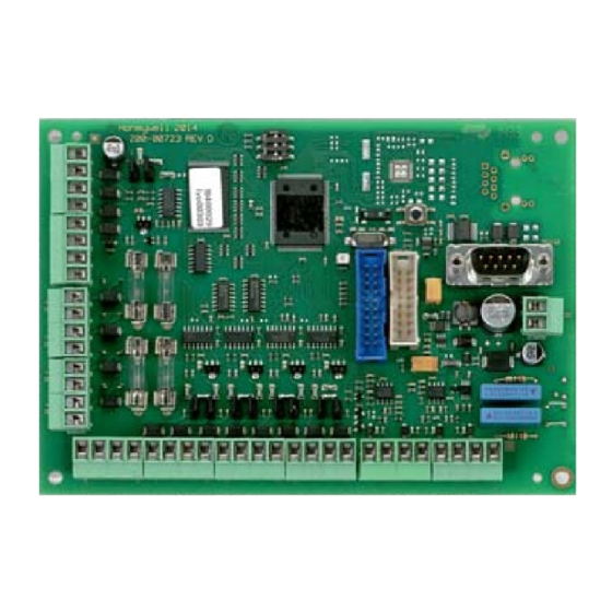
Inhaltszusammenfassung für Honeywell 013930
- Seite 1 Montage-Anschluss-Anleitung IB2 BUS-Erweiterung Art.-Nr. 013930 P00184-10-002-05 Anerkennung Änderungen G115070 vorbehalten 2017-05-10...
-
Seite 2: Inhaltsverzeichnis
Montage-Anschluss-Anleitung IB2 BUS-Erweiterung Inhaltsverzeichnis Seite 1. Anwendung ............. . . 3 2. -
Seite 3: Anwendung
Montage-Anschluss-Anleitung IB2 BUS-Erweiterung Anwendung Die IB2 BUS-Erweiterung dient zum Ausbau einer MB-Secure Zentrale um zusätzliche BUS-2- oder RS-485-Stränge (umschaltbar) und eine RS-232-Schnittstelle. Die Verbindung zur MB-Secure erfolgt über den IB2 BUS, dabei kann das Modul sowohl im Zentralengehäuse als auch abgesetzt mit bis zu 2000 m Kabellänge betrieben werden. Für den Betrieb der BUS-2-Teilnehmer stehen 4 unabhängige und einzeln abgesicherte BUS-2 Ausgänge zur Verfügung. -
Seite 4: Funktionsbeschreibung
Montage-Anschluss-Anleitung IB2 BUS-Erweiterung Funktionsbeschreibung Anschluss an die Zentrale Die IB2 BUS-Schnittstelle der IB2 BUS-Erweiterung wird an einem der 4 Controller-Anschlüsse Zentrale MB-Secure angeschlossen. Die Schnittstelle der Zentrale muss als RS-485/IB2-Schnitt- stelle konfiguriert werden. Bus-Ausgänge Die 4 Bus-Ausgänge sind über die Zentralenprogrammierung einzeln als BUS-2- oder RS-485- Schnittstelle konfigurierbar (RS-485 in Vorbereitung). -
Seite 5: Montage
Montage-Anschluss-Anleitung IB2 BUS-Erweiterung Montage Richtlinien Die Montage erfolgt auf dem Metall-Gehäuseboden der Zentrale oder in einem abgesetzten Metallgehäuse. Die Platinengröße entspricht den bisher bekannten I-BUS Modulen. Beachten Sie das Kap. "Erdung und Abschirmung" in der Installationsanleitung der Zentrale MB- Secure. Bei Anlagen gemäß... -
Seite 6: Installationsrichtlinien
Montage-Anschluss-Anleitung IB2 BUS-Erweiterung Installationsrichtlinien Bus-Anschlussleitungen Die Bus-Anschlussleitung muss als eine abgeschirmte, paarweise verseilte Leitung ausgeführt sein. Hierbei muss die Adernführung nach dem unten angegebenen Schema erfolgen. Die entsprechenden Leiterquerschnitte sind in der Installationsanleitung der Einbruchmelderzentrale (Kapitel Leitungen) zu entnehmen. Schirm im Gehäuse jeweils an der Schirm-Anschlussleiste anschließen. Halten Sie die Schirm- anschlüsse möglichst kurz, um die Gefahr eines Kurzschlusses zu vermeiden. -
Seite 7: Richtlinien Rs-485- Und Ib2-Bus
Montage-Anschluss-Anleitung IB2 BUS-Erweiterung Richtlinien RS-485- und IB2-Bus 5.3.1 Abschlusswiderstände Mit den Jumpern JP1 bis JP4 werden die Abschlusswiderstände der 4 RS-485 -Schnittstellen, mit JP5 die Abschlusswiderstände der IB2 BUS -Schnittstelle aktiviert oder deaktiviert. Grundsätzlich gilt: Die Bus-Leitung muss an beiden Enden mit jeweils abgeschlossen sein. -
Seite 8: Anschlussplan
Montage-Anschluss-Anleitung IB2 BUS-Erweiterung Anschlussplan Übersicht Zentrale MB-Secure Controller-Anschluss 1 – 4 IB2 Bus-Erweiterung +12 V DC IB2 BUS Nicht 4x 1AF belegen U_b5 +12 V DC U_b1 zu A1 +12 V DC +12 V DC U_b2 zu A2 Betriebsspannung Modul +12 V DC U_b3 zu A3 +12 V DC... -
Seite 9: Analog-Eingänge
Montage-Anschluss-Anleitung IB2 BUS-Erweiterung Analog-Eingänge Double balanced: (Details siehe Kap. 3.3) Meldergruppe: E1-E4 z. B. Öffnungskontakt Störung E1-E4 Alarm 12k1 Wert abhängig von der Programmierung. E1 mit Löschfunktion Sabotage Firmware-Update mit FFAST DIP-Schalter 1 DIP-Schalter 1 Reset Reset RS-232 RS-232 U_b5 U_b5 RS-232-Schnittstelle mit PC/Laptop verbinden. -
Seite 10: Technische Daten
Gewicht Platine 163 g Abmessungen Platine (B x H x T) 112 x 158 x 20 mm Konformität: Das Modul Art.-Nr. 013930 ist konform zu EN 50131-3, Grad 3, Klasse II Entspricht SES-EMA-RL-T2:2010-08 Honeywell Security and Fire Novar GmbH Johannes-Mauthe-Straße 14... - Seite 11 Mounting and Connection Instructions IB2 Bus Expander Item no. 013930 P00184-10-002-05 Subject to change approval G115070 without notice 2017-05-10...
-
Seite 12: Security Notes
Mounting and Connection Instructions IB2 Bus Expander Contents Page 1. Application ............. . . 13 2. -
Seite 13: Application
Mounting and Connection Instructions IB2 Bus Expander Application The IB2 BUS expander is intended for the extension of an MB-Secure control panel with additional BUS-2 or RS-485 lines (switchable) and an RS-232 interface. The connection to the MB-Secure is established via the IB2 BUS. The module can be operated both in the panel housing and remotely with a cable length of up to 2000 m. -
Seite 14: Function Description
Mounting and Connection Instructions IB2 Bus Expander Function description Connection to panel MB-Secure The IB2 BUS interface of the IB2 BUS expander is connected to one of the 4 controller connections of the control panel MB-Secure. The interface of the control panel must be configured as an RS-485/IB2 interface. -
Seite 15: Mounting
Mounting and Connection Instructions IB2 Bus Expander Mounting Guidelines Mounting on the metal housing base of the control panel or in a separate metal housing. The circuit board size corresponds with the existing I-BUS modules. Please refer to Chapter “Grounding and Shielding” in the Instructions for the Installer of the MB- Secure control panel. -
Seite 16: Installation Guidelines
Mounting and Connection Instructions IB2 Bus Expander Installation guidelines Bus connection lines The BUS connecting cable must be a shielded, twisted pair line. Wires must correspond with the diagram below. The corresponding line cross-sections can be found in the installation instructions of the intruder alarm control panel (see "Lines"). -
Seite 17: Guidelines Rs-485 And Ib2 Bus
Mounting and Connection Instructions IB2 Bus Expander Guidelines RS-485 and IB2 bus 5.3.1 Bus End of line resistors (EOL) With jumpers JP1 to JP4 the EOL resistors of the 4 RS-485 interfaces are activated/deactivated, with jumper JP5 the EOL resistor of the IB2 BUS interface is activated/deactivated. -
Seite 18: Connection Diagram
Mounting and Connection Instructions IB2 Bus Expander Connection diagram Overview Panel MB-Secure Controller (1 – 4) +12 V DC IB2 Bus Expander IB2 BUS Do not 4x 1AF U_b5 +12 V DC U_b1 to Out1 +12 V DC Out1 +12 V DC U_b2 to Out2 Operating voltage for the module... -
Seite 19: Analogue Inputs
Mounting and Connection Instructions IB2 Bus Expander Analogue inputs Double balanced: (Details see chapt. 3.3) Detector group: In1-In4 e.g. opening contact Fault In1-In4 Alarm 12k1 Value depends on Programming. Input In1 with clear function Tamper Firmware update with FFAST DIP switch 1 Reset Reset RS-232... -
Seite 20: Technical Data
Relative humidity 93% non-condensing Weight 163 g Dimensions 112 x 158 x 20 mm Conformity: Module 013930 as per EN 50131-3, Security grade 3, Environmental Class II As per SES-EMA-RL-T2:2010-08 Honeywell Security and Fire Novar GmbH Johannes-Mauthe-Straße 14 P00184-10-002-05 D-72458 Albstadt 2017-05-10 www.honeywell.com/security/de...


