Viessmann 5224 Bedienungsanleitung
Steuermodul für lichtsignale digital/analog
Vorschau ausblenden
Andere Handbücher für 5224:
- Gebrauchsanleitung (16 Seiten) ,
- Bedienungsanleitung (20 Seiten) ,
- Bedienungsanleitung (20 Seiten)
Inhaltsverzeichnis
Bedienungsanleitung
Operation Manual
5224
Steuermodul für
Lichtsignale digital/analog
Control module for
colour light signals
digital/analogue
1. Wichtige Hinweise / Important information ....................................................... 2
2. Einleitung / Introduction.................................................................................... 2
3. Anschluss / Connection.................................................................................... 3
4. Konfiguration des Steuermoduls / Configuring the control module .................. 5
6. Der Viessmann-Signalbus / The Viessmann signal bus .................................. 7
7. Die Signal-Logik / The signal logic ................................................................... 8
8. Das Vorsignal / The distant signal .................................................................... 17
9. Ansteuerung im Digitalbetrieb / Digital operation ............................................. 18
10. Gewährleistung / Warranty ............................................................................... 20
11. Technische Daten / Technical data .................................................................. 20
DCC MM
DC
AC
~
=
Innovation,
die bewegt!
Inhaltsverzeichnis

Verwandte Anleitungen für Viessmann 5224


Inhaltszusammenfassung für Viessmann 5224
-
Seite 1: Inhaltsverzeichnis
4. Konfiguration des Steuermoduls / Configuring the control module ....5 5. Programmierung des Steuermoduls / Programming the control module ..6 6. Der Viessmann-Signalbus / The Viessmann signal bus ........7 7. Die Signal-Logik / The signal logic ..............8 8. -
Seite 2: Wichtige Hinweise / Important Information
2. Introduction Das Viessmann Steuermodul für Lichtsignale The Viessmann control module for colour light sig- nals item 5224 is designed for a two- or multi-as- Art. 5224 steuert ein zwei- oder mehrbegriffiges pect colour light signal with the associated distant Tageslicht-Signal mit dem dazu gehörenden Vorsi-... -
Seite 3: Anschluss / Connection
If you intend to use several control modules then you le mit Hilfe der Viessmann Tasten-Stellpulte Art. can wire them with the Viessmann signal bus (see fig. 6). 5547 (für vier 2-begriffige Signale), 5546 (für zwei Please note the direction of the signal bus. It transmits 3-begriffige Signale) und 5545 (für zwei 4-begrif-... -
Seite 4: Dunkelschaltung Vorsignal Am Mast
(Kapitel 6). ets. Definition Anschluss COM: Gemeinsamer Rück- The daylight signal module 5224 can generate all leiter aller fünf Eingänge, muss immer mit Buchse signal aspects of the DB main and distant signals. Strom (rt) verbunden werden. Bei verschiedenen The sockets “Bremsen”... -
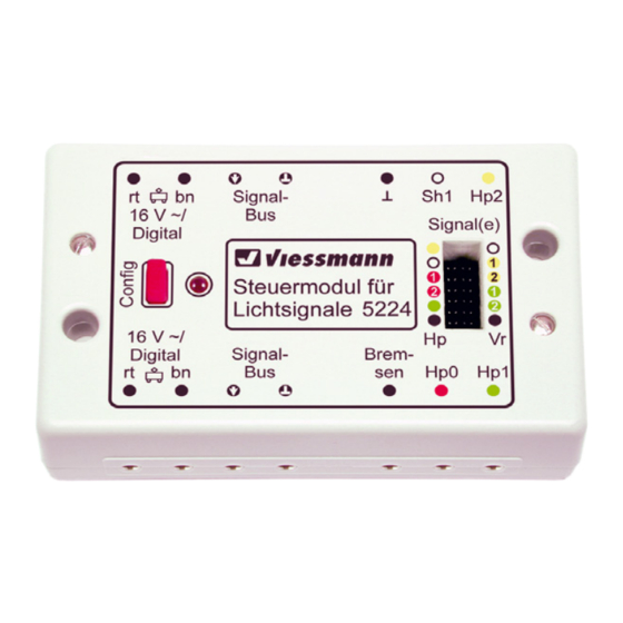
Seite 5: Konfiguration Des Steuermoduls / Configuring The Control Module
Das Steuermodul Art. 5224 ist für viele Signaltypen The Viessmann digital control module for colour sowie die Digitalsysteme Märklin-Motorola bzw. light signals item 5224 is suitable for many types NMRA-DCC geeignet. Deshalb muss es vor dem of signals as well as Märklin Motorola and NMRA Einsatz auf der Modellbahn-Anlage konfiguriert wer- DCC. -
Seite 6: Programmierung Des Steuermoduls / Programming The Control Module
Schritt der Konfiguration über, der Programmierung für den Einsatz im Märklin-Motorola-Format. Abb. 1a zeigt als Beispiel eine Kabelbrückung für die Einstellung auf ein mehrbegriffiges Hauptsignal (Buchse Hp0) und für das Signal mit am eigenen Mast montierten Vorsignal, das zum folgenden Hauptsignal gehört (Buchse Hp1). -
Seite 7: Der Viessmann-Signalbus / The Viessmann Signal Bus
Wichtig: Der Signalbus ist nicht an ein Digitalsystem without any restrictions in analogous mode! The gebunden. Er funktioniert auch bei konventionellem signal bus of item 5224 is compatible with the Betrieb ohne Einschränkungen! Der Signalbus von signal bus of item 5229 Multiplexer for colour Art. -
Seite 8: Die Signal-Logik / The Signal Logic
Setzen Sie bei einem Signal mit Bahnhofssig- connected by the Viessmann signal bus in order nal-Logik Mehrbereichssignale oder Signale ein, to enable the signals to show the correct aspect. - Seite 9 5232 im Märklin-Motorola-Betrieb 5232 in Märklin Motorola mode Das Viessmann Bremsmodul Art. 5232 können Sie You may use the Viessmann digital brake mod- unabhängig von der eingestellten Signallogik einset- ule item 5232 regardless of the signal logic. zen. Es sorgt dafür, dass ein Zug vor einem auf „Halt“...
-
Seite 10: Einsatz Eines Bremsgenerators Im Dcc-Betrieb
Betrieb brake generator in multi-protocol mode Weder das Viessmann Digital-Bremsmodul Art. 5232 Neither the Viessmann digital brake module item noch die DCC-Bremsgeneratoren sind in der Regel 5232 nor the DCC brake generators are suitable für den Einsatz in Multiprotokoll-Systemen geeignet. - Seite 11 Abb. 1 Polarität bei Märklin-Motorola Fig. 1 Polarity for Märklin Motorola...
- Seite 12 Abb. 1a Beispiel einer Kabelbrückung Fig. 1a Example of cable bridging...
- Seite 13 Abb. 2 Fig. 2 Anschluss an Licht-Blocksignal und Vorsignal Connection to colour light block signal and distant signal 5224 z. B. / e. g. 4011 Diode z. B./ Universal Tasten - Stellpult e. g. 4010 Viessmann 5547 Push-button panel 2-aspects, e. g. 5547 Abb.
- Seite 14 Abb. 4 Anschluss an Licht-Ausfahrsignal mit Vorsignal Fig. 4 Connection to colour light departure signal with distant signal 5224 z. B./e. g. 4016 Diode Tasten-Stellpult 4-begriffig viessmann 5545 Push-button panel 4-aspects, e. g. 5545...
- Seite 15 Abb. 5 Anschluss an Licht-Sperrsignal Fig. 5 Connection to colour light block signal 5224 z. B./e. g. 4018 Diode Tasten-Stellpult 2-begriffig Viessmann 5547 Push-button panel 2-aspects, e. g. 5547...
-
Seite 16: Verzweigung Signalbus
„Plus“ geschaltete elektronische we recommend the electronic relay 2 x 2 UM item Relais 2 x 2 UM Art. 5552 von Viessmann. 5552 by Viessmann, switched from positive supply. Zum Betrieb mit Roco oder Lenz Decodern emp- To operate with Roco or Lenz decoders we recom- fehlen wir das von „Masse“... -
Seite 17: Das Vorsignal / The Distant Signal
Anschluss des Zugbeeinflussungsrelais Fig. 8 Installation of relay for train control AC/DC/Digital Signalbus/signal bus 5228 5224 Signalbus/signal bus z. B./e. g. 4010 z. B./e. g. 4012 8. Das Vorsignal 8. The distant signal Das Steuermodul gibt bei der Konfiguration „eigenes The control module sets a separate distant signal Vorsignal“... -
Seite 18: Ansteuerung Im Digitalbetrieb / Digital Operation
5228 (see fig. 8, bzw. die Umschaltung des Fahrstroms übernimmt upper track for 2 rail version, lower track for 3 rail das ansteckbare Viessmann Zugbeeinflussungsre- version). lais Art. 5228 (siehe Abb. 8, oberes Gleis 2-Leiter, unteres Gleis 3-Leiter Variante). - Seite 19 Abb. 10 Anschluss eines möglichen DCC-Bremsgenerators Fig. 10 Connection of a possible DCC brake generator NMRA-DCC Signalbus/signal bus 5228 5224 Signalbus signal bus z. B./e. g 4012 z. B./e. g. 4010 Abb. 11 Verwendung der Kabel Fig. 11 Using the cables...
-
Seite 20: Gewährleistung / Warranty
Sie bitte Kontakt mit uns auf (service@ ment (service@viessmann-modell.com). Please viessmann-modell.com).Senden Sie uns den Artikel send the item to the Viessmann service depart- zur Kontrolle bzw. Reparatur bitte erst nach Rück- ment for check and repair only after consultation.