Gemü R629 eSyLite Betriebsanleitung
Vorschau ausblenden
Andere Handbücher für R629 eSyLite:
- Betriebsanleitung (31 Seiten) ,
- Betriebsanleitung (40 Seiten) ,
- Betriebsanleitung (43 Seiten)

Verwandte Anleitungen für Gemü R629 eSyLite


Inhaltszusammenfassung für Gemü R629 eSyLite
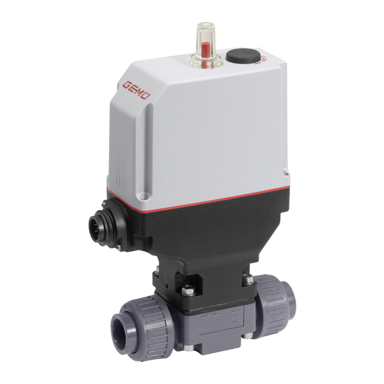
- Seite 1 GEMÜ R629 eSyLite Elektromotorisch betätigtes Membranventil Motorized diaphragm valve Betriebsanleitung Operating instructions...
-
Seite 2: Inhaltsverzeichnis
Inhaltsverzeichnis 1 Allgemeines .............. Hinweise .............. Verwendete Symbole .......... Begriffsbestimmungen ........Warnhinweise ............2 Sicherheitshinweise ..........3 Produktbeschreibung ..........4 GEMÜ CONEXO ............6 Bestelldaten .............. 7 Technische Daten ............. 8 Abmessungen ............12 9 Herstellerangaben ............. 21 Lieferung .............. 21 Verpackung ............ -
Seite 3: Allgemeines
1 Allgemeines 1 Allgemeines WARNUNG Möglicherweise gefährliche Situation! 1.1 Hinweise ▶ Bei Nichtbeachtung drohen schwerste – Beschreibungen und Instruktionen beziehen sich auf Verletzungen oder Tod. Standardausführungen. Für Sonderausführungen, die in diesem Dokument nicht beschrieben sind, gelten die grundsätzlichen Angaben in diesem Dokument in Ver- VORSICHT bindung mit einer zusätzlichen Sonderdokumentation. -
Seite 4: Sicherheitshinweise
2 Sicherheitshinweise 2 Sicherheitshinweise 3 Produktbeschreibung Die Sicherheitshinweise in diesem Dokument beziehen sich 3.1 Aufbau nur auf ein einzelnes Produkt. In Kombination mit anderen An- lagenteilen können Gefahrenpotentiale entstehen, die durch eine Gefahrenanalyse betrachtet werden müssen. Für die Er- stellung der Gefahrenanalyse, die Einhaltung daraus resultie- render Schutzmaßnahmen sowie die Einhaltung regionaler Si- cherheitsbestimmungen, ist der Betreiber verantwortlich. -
Seite 5: Gemü Conexo
5 Bestimmungsgemäße Verwendung 4 GEMÜ CONEXO 5 Bestimmungsgemäße Verwendung Der RFID-Chip dient zur Erhöhung der Prozesssicherheit und GEFAHR der internen Identifizierung. Eine nachträgliche Erweiterung um die CONEXO-Funktionalität für das Produkt muss mit Explosionsgefahr GEMÜ besprochen werden. ▶ Gefahr von Tod oder schwersten Ver- letzungen. -
Seite 6: Bestelldaten
6 Bestelldaten 6 Bestelldaten Bestellcodes Die Bestelldaten stellen eine Übersicht der Standard-Konfigu- 4 Anschlussart Code rationen dar. Armaturenverschraubung mit Einlegeteil Zoll - Vor Bestellung die Verfügbarkeit prüfen. Weitere Konfiguratio- ASTM (Muffe) nen auf Anfrage. Armaturenverschraubung mit Einlegeteil JIS (Muffe) 1 Typ Code Flareanschluss mit Überwurfmutter PVDF Membranventil, elektrisch betätigt,... - Seite 7 6 Bestelldaten Bestelloption Code Beschreibung 9 Antriebsausführung Antriebsgröße 1 Membrangröße 20 7 / 64 www.gemu-group.com GEMÜ R629...
-
Seite 8: Technische Daten
7 Technische Daten 7 Technische Daten 7.1 Medium Betriebsmedium: Aggressive, neutrale, gasförmige und flüssige Medien, die die physikalischen und chemischen Ei- genschaften des jeweiligen Gehäuse- und Membranwerkstoffes nicht negativ beeinflussen. Das Ventil ist in beiden Durchflussrichtungen bis zum vollen Betriebsdruck dicht (Überdruck). 7.2 Temperatur Medientemperatur: PVC-U, grau... - Seite 9 7 Technische Daten Kv-Werte: Kv-Werte ermittelt gemäß DIN EN 60534, Ventilkörperwerkstoff PP mit Anschluss Armaturenver- schraubung Einlegeteil DIN. Die Kv-Werte für andere Produktkonfigurationen (z. B. andere Membran- oder Körperwerkstoffe) können abweichen. Im allgemeinen unterliegen alle Membranen den Einflüssen von Druck, Tempe- ratur, des Prozesses und den Drehmomenten mit denen diese angezogen werden.
-
Seite 10: Mechanische Daten
7 Technische Daten 7.4 Produktkonformitäten EMV-Richtlinie: 2014/30/EU Angewandte Normen: Störaussendung: DIN EN 61000-6-4 Störfestigkeit: DIN EN 61000-6-2 7.5 Werkstoffe Werkstoffe: Membranwerkstoff Werkstoff O-Ring PTFE EPDM EPDM EPDM 7.6 Mechanische Daten Schutzart: IP 65 nach EN 60529 Durchflussrichtung: beliebig Einbaulage: beliebig Gewicht: Antrieb MG 10: 0,85 kg | MG 20: 0,88 kg... -
Seite 11: Elektrische Daten
7 Technische Daten 7.7 Elektrische Daten Versorgungsspannung: 24 V DC Toleranz ± 10 % Stellzeit: MG 10: 2,5 s | MG 20: 3,5 s Einschaltdauer: max. 30% ED Anlaufstrom / ca. 2,8 A Maximalstrom: Stromaufnahme beim ca. 1,4 A Dichtschließen: Stromaufnahme Standby: ca. -
Seite 12: Abmessungen
8 Abmessungen 8 Abmessungen 8.1 Antriebsmaße 134,5 59,5 Maße in mm MG = Membrangröße * CT = A + H1 (siehe Körpermaße) 12 / 64 GEMÜ R629 www.gemu-group.com... -
Seite 13: Körpermaße
8 Abmessungen 8.2 Körpermaße 8.2.1 Anschluss Armaturenverschraubung Code 7 Werkstoffe MG 10 MG 20 Code DN 12 DN 15 DN 20 DN 15 DN 20 DN 25 G 1 1/4 G 1 1/2 øD ød 71, 75 Maße in mm MG = Membrangröße 1) Werkstoff Ventilkörper Code 1: PVC-U, grau... -
Seite 14: Anschluss Armaturenverschraubung Code 33, 3M
8 Abmessungen 8.2.2 Anschluss Armaturenverschraubung Code 33, 3M Anschlussarten Werkstoffe MG 20 Code Code DN 15 DN 20 DN 25 1/2” 3/4” 1” G 1 1/4 G 1 1/2 øD 43,0 53,0 60,0 108,0 108,0 116,0 36,0 38,0 39,0 10,0 12,0 13,0 146,0... -
Seite 15: Anschluss Armaturenverschraubung Code 3T
8 Abmessungen 8.2.3 Anschluss Armaturenverschraubung Code 3T MG 20 DN 15 DN 20 DN 25 G 1 1/4 G 1 1/4 G 1 1/2 øD ød Maße in mm MG = Membrangröße 8.2.4 Anschluss Armaturenverschraubung Code 7R MG 20 DN 15 DN 20 DN 25 G 1 1/4... - Seite 16 8 Abmessungen 8.2.5 Anschluss Armaturenverschraubung Code 78 Werkstoffe MG 20 Code DN 15 DN 20 DN 25 108,0 108,0 116,0 214,0 220,0 234,0 36,0 38,0 39,0 10,0 12,0 13,0 øD 43,0 53,0 60,0 ød 20,0 25,0 32,0 G 1 1/4 G 1 1/2 36,0 37,0...
- Seite 17 8 Abmessungen 8.2.6 Anschluss Stutzen Code 0, 30 Anschlussarten Code Werkstoffe Code 5, 20 5, 20 1, 4 ød ød 1/2" 124,0 36,0 36,0 10,0 20,0 16,0 18,0 141,0 36,0 10,0 21,4 24,0 3/4" 144,0 38,0 38,0 12,0 25,0 19,0 19,0 144,0 38,0...
- Seite 18 8 Abmessungen 8.2.7 Anschluss Stutzen Code 20 Anschlussarten Code 20 Werkstoffe Code ød 1/2" 154,0 36,0 10,0 20,0 33,0 3/4" 154,0 38,0 12,0 25,0 33,0 1" 154,0 39,0 13,0 32,0 33,0 Maße in mm MG = Membrangröße 1) Anschlussart Code 20: Stutzen zum IR-Stumpfschweißen 2) Werkstoff Ventilkörper Code 20: PVDF Code 71: Inliner PP-H, grau, Outliner PP, verstärkt...
- Seite 19 8 Abmessungen 8.2.8 Anschluss Flansch Code 4 Anschlussarten Code 4 Werkstoffe Code 5, 20 5, 20 5, 20 5, 20 øD øL ød øk 130,0 36,0 10,0 95,0 95,0 14,0 14,0 45,0 45,0 65,0 65,0 150,0 38,0 12,0 105,0 105,0 14,0 14,0 58,0...
- Seite 20 8 Abmessungen 8.2.9 Anschluss Flansch Code 39 Anschlussarten Code 39 Werkstoffe Code 5, 20 5, 20 5, 20 5, 20 øD øL ød øk 130,0 36,0 10,0 95,0 95,0 16,0 16,0 45,0 45,0 60,0 60,0 150,0 38,0 12,0 105,0 105,0 16,0 16,0 54,0...
-
Seite 21: Herstellerangaben
10 Einbau in Rohrleitung 9 Herstellerangaben 10 Einbau in Rohrleitung 9.1 Lieferung 10.1 Einbauvorbereitungen ● Ware unverzüglich bei Erhalt auf Vollständigkeit und Un- WARNUNG versehrtheit überprüfen. Unter Druck stehende Armaturen! Das Produkt wird im Werk auf Funktion geprüft. Der Lieferum- ▶... -
Seite 22: Einbaulage
10 Einbau in Rohrleitung 10.3 Einbau mit Schweißstutzen HINWEIS Werkzeug! ▶ Benötigtes Werkzeug für Einbau und Montage ist nicht im Lieferumfang enthalten. Passendes, funktionsfähiges und sicheres Werkzeug ver- ● wenden. Abb. 1: Schweißstutzen 1. Eignung des Produkts für den jeweiligen Einsatzfall sicher- 1. -
Seite 23: Einbau Mit Armaturenverschraubung
10 Einbau in Rohrleitung 10.6 Einbau mit Armaturenverschraubung HINWEIS Gewindedichtmittel! ▶ Das Gewindedichtmittel ist nicht im Lieferumfang enthal- ten. Nur geeignetes Gewindedichtmittel verwenden. ● 1. Gewindedichtmittel bereithalten. 2. Einbauvorbereitungen durchführen (siehe Kapitel "Einbau- Abb. 4: Gewindestutzen vorbereitungen"). 3. Rohr entsprechend der gültigen Normen in Gewindean- HINWEIS schluss des Ventilkörpers schrauben. -
Seite 24: Einbau Mit Flareanschluss
10 Einbau in Rohrleitung 10.8 Einbau mit Flareanschluss HINWEIS Fittinge ▶ Vorbereitung und Anschluss der Flare-Anschlüsse siehe auch GEMÜ FlareStar ® -Prospekt und GEMÜ Flare- und Montageanleitung. Je nach Umgebungsbedingungen beständige und geeig- ● nete Anschlussfittinge benutzen. 1. Montagevorbereitungen durchführen (siehe Kapitel „Mon- tagevorbereitungen“). -
Seite 25: Elektrischer Anschluss
11 Elektrischer Anschluss 11 Elektrischer Anschluss HINWEIS Passende Gegensteckdose / passender Gegenstecker ▶ Für X1 liegt die passende Steckverbindung bei. 11.1 Lage der Steckverbinder 11.2 Elektrischer Anschluss Anschluss X1 7-poliger Stecker Fa. Binder, Typ 693 Signalname 24 V Versorgungsspannung Digitaleingang AUF Digitaleingang ZU n.c. -
Seite 26: Bedienung
12 Bedienung 12 Bedienung 13 Inspektion und Wartung WARNUNG 12.1 Handnotbetätigung Unter Druck stehende Armaturen! WARNUNG ▶ Gefahr von schwersten Verletzungen oder Tod. Beschädigung des Produkts Anlage drucklos schalten. ● ▶ Gefahr der Beschädigung des Produkts Anlage vollständig entleeren. ● ▶... -
Seite 27: Ersatzteile
13 Inspektion und Wartung 13.1 Ersatzteile 13.4 Druckstück montieren 1. Druckstück lose auf Antriebsspindel aufsetzen. 2. Aussparungen D in Führungen C einpassen. ð Das Druckstück muss sich frei zwischen den Führungen bewegen lassen. 13.5 Membrane montieren 13.5.1 Konvex-Membrane montieren Position Benennung Bestellbezeich- nung... -
Seite 28: Konkav-Membrane Montieren
13 Inspektion und Wartung 13.5.2 Konkav-Membrane montieren Druckstückaussparung Membranpin Membranschild Membranpin Membrandom 1. Antrieb A in Geschlossen-Position bringen. Abb. 5: Membranschild umklappen 2. Druckstück montieren (siehe „Druckstück montieren). 3. Kontrollieren, ob das Druckstück in den Führungen liegt. Verbindungsstück Druckstückaussparung 4. Neue Membrane von Hand in das Druckstück hineindre- hen. - Seite 29 13 Inspektion und Wartung ð Gleichmäßige Verpressung ist an gleichmäßiger Au- ßenwölbung erkennbar. 8. Komplett montiertes Ventil auf Funktion und Dichtheit prü- fen. 9. Initialisierung durchführen. www.gemu-group.com 29 / 64 GEMÜ R629...
-
Seite 30: Fehlerbehebung
14 Fehlerbehebung 14 Fehlerbehebung 14.1 Fehlerbehebung Fehler Möglicher Grund Fehlerbehebung Das Produkt ist im Durchgang undicht Betriebsdruck zu hoch Das Produkt mit Betriebsdruck laut (schließt nicht bzw. nicht vollständig) Datenblatt betreiben Fremdkörper zwischen Antrieb demontieren, Fremdkörper Absperrmembrane und Ventilkörpersteg entfernen, Absperrmembrane und Ventilkörpersteg auf Beschädigungen prüfen, ggf. -
Seite 31: Ausbau Aus Rohrleitung
17 Rücksendung 15 Ausbau aus Rohrleitung 17 Rücksendung 1. Den Ausbau in umgekehrter Reihenfolge wie den Einbau Aufgrund gesetzlicher Bestimmungen zum Schutz der Umwelt durchführen. und des Personals ist es erforderlich, dass die Rücksendeer- klärung vollständig ausgefüllt und unterschrieben den Ver- 2. -
Seite 32: Einbauerklärung Nach 2006/42/Eg (Maschinenrichtlinie)
18 Einbauerklärung nach 2006/42/EG (Maschinenrichtlinie) 18 Einbauerklärung nach 2006/42/EG (Maschinenrichtlinie) Einbauerklärung im Sinne der EG-Maschinenrichtlinie 2006/42/EG, Anhang II, 1.B für unvoll- ständige Maschinen Wir, die Firma GEMÜ Gebr. Müller Apparatebau GmbH & Co. KG Fritz-Müller-Straße 6-8 D-74653 Ingelfingen-Criesbach erklären, dass das folgende Produkt Fabrikat: GEMÜ... -
Seite 33: Konformitätserklärung Nach 2014/30/Eu (Emv-Richtlinie)
19 Konformitätserklärung nach 2014/30/EU (EMV-Richtlinie) 19 Konformitätserklärung nach 2014/30/EU (EMV-Richtlinie) EU-Konformitätserklärung gemäß 2014/30/EU (EMV-Richtlinie) Wir, die Firma GEMÜ Gebr. Müller Apparatebau GmbH & Co. KG Fritz-Müller-Straße 6-8 D-74653 Ingelfingen-Criesbach erklären, dass das unten aufgeführte Produkt die Sicherheitsanforderungen der EMV-Richtlinie 2014/30/EU erfüllt. Benennung des Produktes: GEMÜ... - Seite 62 62 / 64 GEMÜ R629 www.gemu-group.com...
- Seite 63 www.gemu-group.com 63 / 64 GEMÜ R629...