Herunterladen Inhalt Inhalt Diese Seite drucken
Dimplex SI 90TU Montage- & Bedienungsanleitung/Gebrauchsanweisung

Dimplex SI 90TU Montage- & Bedienungsanleitung/Gebrauchsanweisung

Vorschau ausblenden Andere Handbücher für SI 90TU:
Inhaltsverzeichnis

Werbung

Verfügbare Sprachen

Verfügbare Sprachen

SI 90TU
SI 130TU
Montage- und
Gebrauchsanweisung
Sole-Wasser-
Wärmepumpe
für Innenaufstellung
Bestell-Nr. | Order no. | No de commande: 452237.66.52
Installation and
Operating Instruction
Brine-to-Water
Heat Pump for
Indoor Installation
Glen
Dimplex
Thermal
Solutions
Instuctions d'installation
et d'utilisation
Pompe à chaleur
eau glycolée-eau pour
installation intérieure
DE | EN | FR · FD 9912
Dimplex

Werbung

Kapitel

Inhaltsverzeichnis
loading

Inhaltszusammenfassung für Dimplex SI 90TU

  • Seite 1 Glen Dimplex Thermal Solutions Dimplex SI 90TU SI 130TU Montage- und Installation and Instuctions d‘installation Gebrauchsanweisung Operating Instruction et d‘utilisation Sole-Wasser- Brine-to-Water Pompe à chaleur Wärmepumpe Heat Pump for eau glycolée-eau pour für Innenaufstellung Indoor Installation installation intérieure Bestell-Nr. | Order no. | No de commande: 452237.66.52...
  • Seite 3: Inhaltsverzeichnis

    SI 90TU - SI 130TU Deutsch Inhaltsverzeichnis Bitte sofort lesen ............................DE-2 1.1 Wichtige Hinweise ................................DE-2 1.2 Bestimmungsgemäßer Gebrauch ..........................DE-2 1.3 Gesetzliche Vorschriften und Richtlinien.........................DE-3 1.4 Energiesparende Handhabung der Wärmepumpe ....................DE-3 Verwendungszweck der Wärmepumpe ....................DE-3 2.1 Anwendungsbereich...............................DE-3 2.2 Arbeitsweise..................................DE-3 Grundgerät..............................DE-4 Zubehör .................................DE-5 4.1 Anschlussflansche................................DE-5...
  • Seite 4: Bitte Sofort Lesen

    Deutsch SI 90TU - SI 130TU ACHTUNG! Bitte sofort lesen Es ist nicht zulässig über einen Relaisausgang mehr als eine elektronisch geregelte Umwälzpumpe zu schalten. 1.1 Wichtige Hinweise ACHTUNG! ACHTUNG! Die Inbetriebnahme erfolgt gemäß der Montage- und Gebrauchsanweisung des Wärmepumpenmanager.
  • Seite 5: Gesetzliche Vorschriften Und Richtlinien

    SI 90TU - SI 130TU Deutsch 1.3 Gesetzliche Vorschriften und Verwendungszweck der Richtlinien Wärmepumpe Diese Wärmepumpe ist gemäß Artikel 1, Abschnitt 2 k) der EU- Richtlinie 2006/42/EC (Maschinenrichtlinie) für den Gebrauch 2.1 Anwendungsbereich im häuslichen Umfeld bestimmt und unterliegt damit den An- forderungen der EU-Richtlinie 2014/35/EU (Niederspannungs- Die Sole/Wasser-Wärmepumpe ist ausschließlich für die Erwär-...
  • Seite 6: Grundgerät

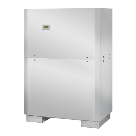
    Deutsch SI 90TU - SI 130TU Grundgerät Das Grundgerät besteht aus einer anschlussfertigen Wärme- pumpe für Innenaufstellung mit Blechgehäuse, Schaltkasten und integriertem Wärmepumpenmanager. Der Kältekreis ist „hermetisch geschlossen“ und enthält das vom Kyoto-Protokoll erfasste fluorierte Kältemittel R410A. Angaben zum GWP-Wert und CO -Äquivalent des Kältemittels finden sich im Kapitel Ge-...
  • Seite 7: Zubehör

    SI 90TU - SI 130TU Deutsch Zubehör Transport Zum Transport auf ebenem Untergrund eignet sich ein Hubwa- 4.1 Anschlussflansche gen. Muss die Wärmepumpe auf unebenem Untergrund oder über Treppen befördert werden, kann dies mit Tragriemen ge- Durch den Einsatz der flachdichtenden Anschlussflansche schehen.
  • Seite 8: Aufstellung

    Deutsch SI 90TU - SI 130TU 7.2 Heizungsseitiger Anschluss Aufstellung ACHTUNG! 6.1 Allgemeine Hinweise Vor Anschluss der Wärmepumpe Heizungsanlage spülen. Die Sole/Wasser-Wärmepumpe muss in einem frostfreien und Bevor die heizwasserseitigen Anschlüsse der Wärmepumpe er- trockenen Raum auf einer ebenen, glatten und waagerechten folgen, muss die Heizungsanlage gespült werden, um eventuell...
  • Seite 9: Wärmequellenseitiger Anschluss

    SI 90TU - SI 130TU Deutsch 7.4 Temperaturfühler Mindestheizwasserdurchsatz Der Mindestheizwasserdurchsatz der Wärmepumpe ist in Folgende Temperaturfühler sind bereits eingebaut bzw. müs- jedem Betriebszustand der Heizungsanlage sicherzustellen. sen zusätzlich montiert werden: Dieses kann z.B. durch Installation eines doppelt differenz- Außentemperatur (R1) beigelegt (NTC-2) ...
  • Seite 10: Verteilsystem Hydraulik

    Deutsch SI 90TU - SI 130TU 7.4.2 Montage des 7.4.4 Verteilsystem Hydraulik Außentemperaturfühlers Kompaktverteiler und doppelt differenzdruckloser Verteiler fungieren als Schnittstelle zwischen der Wärmepumpe, dem Der Temperaturfühler muss so angebracht werden, dass sämt- Heizungsverteilsystem, dem Pufferspeicher und evtl. auch dem liche Witterungseinflüsse erfasst werden und der Messwert...
  • Seite 11: Elektrischer Anschluss

    SI 90TU - SI 130TU Deutsch 7.5 Elektrischer Anschluss 7.5.2 Elektrische Anschlussarbeiten Die 4-adrige elektrische Versorgungsleitung für den Leis- 7.5.1 Allgemein tungsteil der Wärmepumpe wird vom Stromzähler der Wärmepumpe über das EVU-Sperrschütz (falls gefordert) Sämtliche elektrische Anschlussarbeiten dürfen nur von einer in die Wärmepumpe geführt (Lastspannung siehe Anwei-...
  • Seite 12: Anschluss Von Elektronisch Geregelten Umwälzpumpen

    Deutsch SI 90TU - SI 130TU 11) Die Sole- bzw. Brunnenpumpe (M11) wird über den Kon- Inbetriebnahme takt N1-J12/NO3 angesteuert. Anschluspunkte für die Pumpe sind X2/M11 und X2/N. Ein Koppelrelais ist in die- 8.1 Allgemeine Hinweise sem Ausgang bereits integriert.
  • Seite 13: Pflege / Reinigung

    SI 90TU - SI 130TU Deutsch Pflege / Reinigung 10 Störungen / Fehlersuche Diese Wärmepumpe ist ein Qualitätsprodukt und sollte stö- 9.1 Pflege rungsfrei arbeiten. Tritt dennoch eine Störung auf, wird diese im Display des Wärmepumpenmanagers angezeigt. Schlagen Sie Um Betriebsstörungen durch Schmutzablagerungen in den dazu auf der Seite Störungen und Fehlersuche in der Montage-...
  • Seite 14: Geräteinformation

    Deutsch SI 90TU - SI 130TU 12 Geräteinformation Typ- und Verkaufsbezeichnung SI 90TU Bauform Wärmequelle Sole Ausführung Universal Regler integriert Wärmemengenzähler integriert Aufstellungsort Innen Leistungsstufen Einsatzgrenzen 20 bis 62 ±2 Heizwasser-Vorlauf °C -5 bis 25 Sole (Wärmequelle) °C Frostschutzmittel Monoethylenglykol 25 % Minimale Solekonzentration (-13 °C Einfriertemperatur)
  • Seite 15: Einsatzgrenzen

    SI 90TU - SI 130TU Deutsch Entspricht den europäischen Sicherheitsbestimmungen Sonstige Ausführungsmerkmale Wasser im Gerät gegen Einfrieren geschützt max. Betriebsüberdruck (Wärmequelle/Wärmesenke) Heizleistung / Leistungszahl EN 14511 Wärmeleistung / Leistungszahl Leistungsstufe bei B-5 / W45 kW / --- 37,3 / 3,4...
  • Seite 16 Deutsch SI 90TU - SI 130TU Schmiermittel / Gesamt-Füllmenge Typ / Liter Polyolester (POE) / 14,6 Volumen Heizwasser im Gerät Liter 5.10 Volumen Wärmeträger im Gerät Liter Elektrischer Anschluss Lastspannung / Absicherung / RCD-Typ 3~/PE 400 V (50 Hz) / C 100A / A...
  • Seite 17: Produktinformationen Gemäß Verordnung (Eu) Nr.813/2013, Anhang Ii, Tabelle 2

    Kontakt Glen Dimplex Deutschland GmbH, Am Goldenen Feld 18, 95326 Kulmbach (*) Für Heizgeräte und Kombiheizgeräte mit Wärmepumpe ist die Wärmenennleistung Prated gleich der Auslegungslast im Heizbetrieb Pdesingh und die Wärmenennleistung eines Zusatzheizgerätes Psup gleich der zusaätzlichen Heizleistung sup(Tj ).
  • Seite 18 Kontakt Glen Dimplex Deutschland GmbH, Am Goldenen Feld 18, 95326 Kulmbach (*) Für Heizgeräte und Kombiheizgeräte mit Wärmepumpe ist die Wärmenennleistung Prated gleich der Auslegungslast im Heizbetrieb Pdesingh und die Wärmenennleistung eines Zusatzheizgerätes Psup gleich der zusaätzlichen Heizleistung sup(Tj ).
  • Seite 19: Garantieurkunde

    SI 90TU - SI 130TU Deutsch Eine Verlängerung der Garantie auf 60 Monate oder mehr für Hei- 14 Garantieurkunde zungs-Wärmepumpen und zentrale Wohnungslüftungsgeräte ab dem Datum der Inbetriebnahme wird gemäß den nachfolgenden Glen Dimplex Thermal Solutions Bedingungen gewährt Garantieurkunde GDTS (Heizungs-Wärmepumpen, Zentrale Wohnungslüftungsgeräte)
  • Seite 20 Deutsch SI 90TU - SI 130TU DE-18 452237.66.52 · FD 9912 www.gdts.one...
  • Seite 21 SI 90TU - SI 130TU English Table of contents Please read immediately..........................EN-2 1.1 Important notes ................................EN-2 1.2 Intended use..................................EN-2 1.3 Legal regulations and directives ..........................EN-3 1.4 Energy-efficient use of the heat pump........................EN-3 Intended use of the heat pump .......................EN-3 2.1 Intended purpose................................EN-3 2.2 Operating principle................................EN-3...
  • Seite 22: Please Read Immediately

    English SI 90TU - SI 130TU ATTENTION! Please read immediately It is not permitted to connect more than one electronically regulated circulating pump via a relay output. 1.1 Important notes ATTENTION! ATTENTION! Start-up must be performed in accordance with the...
  • Seite 23: Legal Regulations And Directives

    SI 90TU - SI 130TU English 1.3 Legal regulations and directives Intended use of the heat This heat pump is designed for use in a domestic environment pump according to Article 1, Paragraph 2 k) of EU directive 2006/42/ EC (machinery directive) and is thus subject to the require- 2.1 Intended purpose...
  • Seite 24: Basic Device

    English SI 90TU - SI 130TU Basic device The basic device consists of a heat pump for indoor installation wired ready for use with metal casing, switch box and inte- grated heat pump manager. The refrigeration circuit is "hermet- ically sealed" and contains the fluorinated refrigerant R410A in- cluded in the Kyoto protocol.
  • Seite 25: Accessories

    SI 90TU - SI 130TU English Accessories Transport A lift truck is suited for transporting the unit on a level surface. 4.1 Connection flange Carrying straps may be used if the heat pump needs to be trans-ported on an uneven surface or carried up or down stairs.
  • Seite 26: Installation

    English SI 90TU - SI 130TU 7.2 Connection on the heating side Installation ATTENTION! 6.1 General Information Flush the heating system prior to connecting the heat pump. The brine-to-water heat pump must be installed in a frost-free, Before connecting the heating water system to the heat pump, dry room on an even, smooth and horizontal surface.
  • Seite 27: Heat Source Connection

    SI 90TU - SI 130TU English 7.4 Temperature sensor Minimum heating water flow rate The minimum heating water flow rate through the heat pump The following temperature sensors are already installed or must must be assured in all operating states of the heating system.
  • Seite 28: Installing The Strap-On Sensor

    English SI 90TU - SI 130TU 7.4.2 Mounting the outside temperature 7.4.4 Hydraulic distribution system sensor The compact manifold and the dual differential pressureless manifold function as an interface between the heat pump, the The temperature sensor must be mounted in such a way that all...
  • Seite 29: Electrical Connection

    SI 90TU - SI 130TU English 7.5 Electrical connection 7.5.2 Electrical installation work The four-core electrical supply cable for the heat pump 7.5.1 General power part is fed from the heat pump electricity meter into the heat pump via the utility company blocking contactor All electrical installation work must be carried out by a trained (if required) (for supply voltage, see heat pump manual).
  • Seite 30: Commissioning

    English SI 90TU - SI 130TU 11) The brine or well pump (M11) is activated via the contact Commissioning N1-J12/NO3. The connection points for the pump are X2/ M11 and X2/N. A coupling relay is already integrated in this 8.1 General Information output.
  • Seite 31: Cleaning / Maintenance

    SI 90TU - SI 130TU English Cleaning / maintenance 10 Faults / troubleshooting This heat pump is a quality product and is designed for trouble- 9.1 Maintenance free operation. In the event that a fault should occur, it will be indicated on the heat pump manager display.
  • Seite 32: Device Information

    English SI 90TU - SI 130TU 12 Device information Type and order code SI 90TU Design Heat source Brine Model Universal Controller integrated Thermal energy meter Integrated Installation location Indoors Performance levels Operating limits 20 to 62 ± 2 Heating water flow °C...
  • Seite 33: Operating Limits

    SI 90TU - SI 130TU English Complies with the European safety regulations Additional model features Water in device is protected against freezing Max. operating overpressure (heat source/heat sink) Heat output / COP EN 14511 Heat output / coefficient of performance (COP)
  • Seite 34 English SI 90TU - SI 130TU Lubricant / total filling quantity type/litres Polyolester (POE) / 14.6 Volume of heating water in device Litres 5.10 Volume of heat transfer medium in device Litres Electrical connection Supply voltage / fuse protection / RCD-Type...
  • Seite 35: Product Information As Per Regulation (Eu) No 813/2013, Annex Ii, Table 2

    Contact details Glen Dimplex Deutschland GmbH, Am Goldenen Feld 18, 95326 Kulmbach (*) For heat pump space heaters and heat pump combination heaters, the rated output Prated is equal to the design load for heating Pdesignh , and the rated heat output of a supplementary capacity for heating sup(Tj ).
  • Seite 36 Contact details Glen Dimplex Deutschland GmbH, Am Goldenen Feld 18, 95326 Kulmbach (*) For heat pump space heaters and heat pump combination heaters, the rated output Prated is equal to the design load for heating Pdesignh , and the rated heat output of a supplementary capacity for heating sup(Tj ).
  • Seite 37 SI 90TU - SI 130TU Français Table des matières À lire immédiatement..........................FR-2 1.1 Remarques importantes ..............................FR-2 1.2 Utilisation conforme................................ FR-2 1.3 Dispositions légales et directives..........................FR-3 1.4 Utilisation de la pompe à chaleur pour économiser de l’énergie ..............FR-3 Utilisation de la pompe à...
  • Seite 38: Remarques Importantes

    Français SI 90TU - SI 130TU ATTENTION ! À lire immédiatement Tenir compte du champ magnétique rotatif vers la droite: si le câblage est mal effectué, la pompe à chaleur ne peut pas 1.1 Remarques importantes démarrer. Un avertissement correspondant s’affiche sur le gestionnaire de pompe à...
  • Seite 39: Dispositions Légales Et Directives

    SI 90TU - SI 130TU Français 1.3 Dispositions légales et Utilisation de la pompe à directives chaleur Cette pompe à chaleur est conçue pour une utilisation dans un environnement domestique selon l’article1 (paragraphe 2k) de 2.1 Domaine d’utilisation la directive UE 2006/42/CE (directive relative aux machines) et est ainsi soumise aux exigences de la directive UE 2014/35/UE La pompe à...
  • Seite 40: Appareil De Base

    Français SI 90TU - SI 130TU Appareil de base L'appareil de base comporte une pompe à chaleur pour instal- lation à l'intérieur, prête à brancher, avec jaquette en tôle, boî- tier électrique et gestionnaire de pompe à chaleur intégré. Le circuit frigorifique est «...
  • Seite 41: Système De Gestion Technique Du Bâtiment

    SI 90TU - SI 130TU Français Accessoires Transport Le transport par chariot élévateur convient bien à un déplace- 4.1 Brides de raccordement ment sur surface plane. Si la pompe à chaleur doit être convoyée sur une surface non plane ou dans des escaliers, il est Les brides de raccordement à...
  • Seite 42: Remarques D'ordre Général

    Français SI 90TU - SI 130TU 7.2 Raccordement côté chauffage Installation ATTENTION ! 6.1 Remarques d'ordre général Rincer l'installation de chauffage avant de raccorder la pompe à chaleur. La pompe à chaleur eau glycolée/eau doit être installée dans un local sec à l’abri du gel, sur une surface plane, lisse et horizon- Avant de procéder aux raccordements de la pompe à...
  • Seite 43: Raccordement Côté Source De Chaleur

    SI 90TU - SI 130TU Français 7.4 Sonde de température Débit minimum d'eau de chauffage Le débit minimum d’eau de chauffage doit être garanti dans la Les sondes de température suivantes sont déjà montées ou pompe à chaleur quel que soit l’état de fonctionnement de doivent être installées en plus:...
  • Seite 44: Montage De La Sonde De Température Extérieure

    Français SI 90TU - SI 130TU 7.4.2 Montage de la sonde de température 7.4.4 Système de distribution hydraulique extérieure Le distributeur compact et la bouteille de découplage hydrau- lique servent d’interface entre la pompe à chaleur, le circuit de La sonde de température doit être placée de telle sorte qu’elle distribution du chauffage, le ballon tampon et éventuellement...
  • Seite 45: Branchements Électriques

    SI 90TU - SI 130TU Français 7.5 Branchements électriques 7.5.2 Branchements électriques La ligne d’alimentation électrique à 4 fils de la partie puis- 7.5.1 Généralités sance de la pompe à chaleur est amenée du compteur de courant de la pompe à chaleur jusqu'à cette dernière (ten- Tous les branchements électriques doivent être effectués ex-...
  • Seite 46: Procédures À Suivre Lors De La Mise En Service

    Français SI 90TU - SI 130TU Le circulateur du circuit de chauffage (M13) est com- Mise en service mandé via le contact N1-J13/NO5. Les points de raccor- dement de la pompe sont X2/M13 et X2/N. En cas d'utili- 8.1 Remarques d'ordre général sation de pompes qui dépassent la capacité...
  • Seite 47: Entretien/Nettoyage

    SI 90TU - SI 130TU Français 9.3 Nettoyage côté source de Entretien/nettoyage chaleur 9.1 Entretien ATTENTION ! Pour éviter des défauts dus à des dépôts dans les échangeurs Monter dans l’entrée de la source de chaleur de la pompe à...
  • Seite 48: Informations Sur Les Appareils

    Français SI 90TU - SI 130TU 12 Informations sur les appareils Désignation technique et référence de commande SI 90TU Design Source de chaleur Eau glycolée Version Universelle Régulateur intégré Calorimètre intégré Emplacement à l’intérieur Niveaux de puissance Plages d’utilisation de 20 à 62 ±2 Départ de l’eau de chauffage...
  • Seite 49: Plages D'utilisation

    SI 90TU - SI 130TU Français Conforme aux dispositions de sécurité européennes Autres caractéristiques techniques Eau de chauffage dans l’appareil protégée du gel Surpression de service max. (source de chaleur/dissipation thermique) bars Puissance calorifique/coefficient de performance EN 14511 Capacité thermique/coefficient de performance...
  • Seite 50 Français SI 90TU - SI 130TU Circuit frigorifique hermétiquement fermé Lubrifiant / capacité totale type/litres Polyolester (POE) / 14,6 Volume d’eau de chauffage dans l’appareil litres 5.10 Volume d'agent caloporteur dans l'appareil litres Branchements électriques Tension de charge / protection par fusible / RCD-Type...
  • Seite 51 Glen Dimplex Deutschland GmbH, Am Goldenen Feld 18, 95326 Kulmbach Coordonnées de contact (*) Pour les dispositifs de chauffage des locaux par pompe à chaleur et les dispositifs de chauffage mixtes par pompe à chaleur, la puissance thermique nominale Prated est égale à...
  • Seite 52 Glen Dimplex Deutschland GmbH, Am Goldenen Feld 18, 95326 Kulmbach Coordonnées de contact (*) Pour les dispositifs de chauffage des locaux par pompe à chaleur et les dispositifs de chauffage mixtes par pompe à chaleur, la puissance thermique nominale Prated est égale à...
  • Seite 53: Anhang / Appendix / Annexes

    3.2 Steuerung / Control / Commande SI 90TU......................A-IX 3.3 Last / Load / Charge SI 90TU ............................A-X 3.4 Anschlussplan / Connection Plan / Schéma de connexion SI 90TU .............. A-XI 3.5 Anschlussplan / Connection Plan / Schéma de connexion SI 90TU ............A-XII 3.6 Legende / Legend / Légende SI 90TU ........................
  • Seite 54: Maßbilder / Dimension Drawings / Schémas Cotés

    Anhang · Appendix · Annexes SI 90TU - SI 130TU 1 Maßbilder / Dimension Drawings / Schémas cotés 1.1 Maßbild / Dimension Drawing / Schéma coté SI 90TU A-II 452237.66.52 · FD 9912 www.gdts.one...
  • Seite 55 SI 90TU - SI 130TU Anhang · Appendix · Annexes 1.2 Maßbild / Dimension Drawing / Schéma coté SI 130TU www.gdts.one 452237.66.52 · FD 9912 A-III...
  • Seite 56: Diagramme / Diagrams / Diagrammes

    Anhang · Appendix · Annexes SI 90TU - SI 130TU 2 Diagramme / Diagrams / Diagrammes 2.1 Kennlinien / Characteristic Curves / Courbes caractéristiques SI 90TU Wasseraustrittstemperatur in [°C] Heizleistung in [kW] Water outlet temperature in [°C] Heating capacity in [kW] Température de sortie de l'eau en [°C]...
  • Seite 57 SI 90TU - SI 130TU Anhang · Appendix · Annexes 2.2 Kennlinien / Characteristic Curves / Courbes caractéristiques SI 130TU Wasseraustrittstemperatur in [°C] Heizleistung in [kW] Water outlet temperature in [°C] Heating capacity in [kW] Température de sortie de l'eau en [°C]...
  • Seite 58 Anhang · Appendix · Annexes SI 90TU - SI 130TU 2.3 Einsatzgrenzendiagramm / Operating limits diagram / Diagramme des seuils d'utilisation SI 90TU Wasseraustritt (+/- 2 K) Water outlet (+/- 2 K) Sortie d'eau (+/- 2 K) Heizwasserdurchfluss min / max...
  • Seite 59 SI 90TU - SI 130TU Anhang · Appendix · Annexes 2.4 Einsatzgrenzendiagramm / Operating limits diagram / Diagramme des seuils d'utilisation SI 130TU Wasseraustritt (+/- 2 K) Water outlet (+/- 2 K) Sortie d'eau (+/- 2 K) Heizwasserdurchfluss min / max...
  • Seite 60: Stromlaufpläne / Circuit Diagrams / Schémas Électriques

    Anhang · Appendix · Annexes SI 90TU - SI 130TU 3 Stromlaufpläne / Circuit Diagrams / Schémas électriques 3.1 Steuerung / Control / Commande SI 90TU A-VIII 452237.66.52 · FD 9912 www.gdts.one...
  • Seite 61 SI 90TU - SI 130TU Anhang · Appendix · Annexes 3.2 Steuerung / Control / Commande SI 90TU www.gdts.one 452237.66.52 · FD 9912 A-IX...
  • Seite 62 Anhang · Appendix · Annexes SI 90TU - SI 130TU 3.3 Last / Load / Charge SI 90TU 452237.66.52 · FD 9912 www.gdts.one...
  • Seite 63 SI 90TU - SI 130TU Anhang · Appendix · Annexes 3.4 Anschlussplan / Connection Plan / Schéma de connexion SI 90TU www.gdts.one 452237.66.52 · FD 9912 A-XI...
  • Seite 64 Anhang · Appendix · Annexes SI 90TU - SI 130TU 3.5 Anschlussplan / Connection Plan / Schéma de connexion SI 90TU A-XII 452237.66.52 · FD 9912 www.gdts.one...
  • Seite 65 SI 90TU - SI 130TU Anhang · Appendix · Annexes 3.6 Legende / Legend / Légende SI 90TU Brücke EVU-Sperre, muss eingelegt werden, wenn Utility block (EVU) bridge must be inserted if no Pont de blocage de la société d'électricité, à...
  • Seite 66 Anhang · Appendix · Annexes SI 90TU - SI 130TU Sanftanlaufsteuerung M3 Soft start control M3 Commande de démarrage progressif M3 Bedienteil Control panel Unité de commande N17* pCOe-Modul pCOe module Module pCOe N20* Wärmemengenzähler Thermal energy meter Compteur de chaleur...
  • Seite 67 SI 90TU - SI 130TU Anhang · Appendix · Annexes 3.7 Steuerung / Control / Commande SI 130TU www.gdts.one 452237.66.52 · FD 9912 A-XV...
  • Seite 68 Anhang · Appendix · Annexes SI 90TU - SI 130TU 3.8 Steuerung / Control / Commande SI 130TU A-XVI 452237.66.52 · FD 9912 www.gdts.one...
  • Seite 69 SI 90TU - SI 130TU Anhang · Appendix · Annexes 3.9 Last / Load / Charge SI 130TU www.gdts.one 452237.66.52 · FD 9912 A-XVII...
  • Seite 70 Anhang · Appendix · Annexes SI 90TU - SI 130TU 3.10 Anschlussplan / Connection Plan / Schéma de connexion SI 130TU A-XVIII 452237.66.52 · FD 9912 www.gdts.one...
  • Seite 71 SI 90TU - SI 130TU Anhang · Appendix · Annexes 3.11 Anschlussplan / Connection Plan / Schéma de connexion SI 130TU www.gdts.one 452237.66.52 · FD 9912 A-XIX...
  • Seite 72 Anhang · Appendix · Annexes SI 90TU - SI 130TU 3.12 Legende / Legend / Légende SI 130TU Brücke EVU-Sperre, muss eingelegt werden, wenn Utility block (EVU) bridge must be inserted if no Pont de blocage de la société d'électricité, à...
  • Seite 73 SI 90TU - SI 130TU Anhang · Appendix · Annexes Sanftanlaufsteuerung M3 Soft start control M3 Commande de démarrage progressif M3 Bedienteil Control panel Unité de commande N17* pCOe-Modul pCOe module Module pCOe N20* Wärmemengenzähler Thermal energy meter Compteur de chaleur...
  • Seite 74: Hydraulische Einbindungsschemen / Hydraulic Integration Diagrams / Schémas D'intégration Hydraulique

    Anhang · Appendix · Annexes SI 90TU - SI 130TU 4 Hydraulische Einbindungsschemen / Hydraulic integration diagrams / Schémas d'intégration hydraulique 4.1 Monovalente Wärmepumpenanlage mit 3 Heizkreisen und Warmwasserbereitung / Monovalent heat pump system with three heating circuits and domestic hot water preparation / Installation monovalente de pompe à...
  • Seite 75 SI 90TU - SI 130TU Anhang · Appendix · Annexes 4.2 Bivalente Wärmepumpenanlage mit zwei Heizkreisen und Warmwasserbereitung / Bivalent system with two heating circuits and domestic hot water preparation / Installation bivalente avec deux circuits de chauffage et production d´eau chaude sanitaire www.gdts.one...
  • Seite 76 Anhang · Appendix · Annexes SI 90TU - SI 130TU 4.3 Legende / Legend / Légende Rückschlagventil Check valve Clapet anti-retour Absperrventil Shutoff valve Robinet d’arrêt Schmutzfänger Dirt trap Filtre Dreiwegemischer Three-way mixer Mélangeur 3 voies Umwälzpumpe Circulating pump Circulateur Ausdehnungsgefäß...
  • Seite 77: Konformitätserklärung / Declaration Of Conformity / Déclaration De Conformité

    SI 90TU - SI 130TU Anhang · Appendix · Annexes 5 Konformitätserklärung / Declaration of Conformity / Déclaration de conformité Die aktuelle CE-Konformitätserklärung finden sie als Download unter: You can find and download the current CE conformity declaration at: Vous pouvez télécharger la déclaration de conformité CE actuelle sous : https://gdts.one/si90tu...
  • Seite 78 Anhang · Appendix · Annexes SI 90TU - SI 130TU A-XXVI 452237.66.52 · FD 9912 www.gdts.one...
  • Seite 79 SI 90TU - SI 130TU Anhang · Appendix · Annexes www.gdts.one 452237.66.52 · FD 9912 A-XXVII...
  • Seite 80 Glen Dimplex Deutschland GmbH Irrtümer und Änderungen vorbehalten. Geschäftsbereich GDTS Subject to alterations and errors. Am Goldenen Feld 18 Sous réserve d’erreurs et modifications. D-95326 Kulmbach +49 (0) 9221 709 924545 www.gdts.one...

Inhaltsverzeichnis