Zur Sicherheit Dieses Kapitel dient Ihrer Sicherheit und der Sicherheit der Anlagenbenut- zer. " Bitte lesen Sie dieses Kapitel sorgfältig, bevor Sie mit dem RE300 oder der durch den RE300 geschützten Maschine arbeiten. Für Verwendung/Einbau des Sicherheitssensors sowie für Inbetriebnahme und wiederkehrende technische Überprüfungen gelten die nationa-...
Der Sensor, der Betätiger und die Auswerteeinheit dürfen nur gemeinsam betrieben werden. Sicherheitssensoren der Typenreihe RE300 erfüllen folgende Sicherheits- anforderungen # Steuerungskategorie 3 nach EN 954-1 # Näherungsschalter nach EN 60947-5-3, Klasse PDF-S SICK AG • Industrial Safety Systems • Deutschland • Alle Rechte vorbehalten 8 009 820/??-??-02...
Seite 6
# Schaltung in der Auswerteeinheit ist redundant aufgebaut. # Beim Öffnen bzw. Schließen der Sicherheitseinrichtung wird überprüft, ob die Relaiskontakte richtig öffnen und schließen. Die Hilfskontakte 31 und 32 (Abb. 4) dürfen nicht als Sicherheitsausgang verwendet werden.
Betätiger an der Schließkante anzubringen (Abb. 3). " Auswerteeinheit in Gehäuse/Schaltschrank (min. IP 54) auf 35-mm- Normschiene montieren. Für die Montage des Sensors und der Betätiger die beiliegenden Metallunterlagen verwenden. SICK AG • Industrial Safety Systems • Deutschland • Alle Rechte vorbehalten 8 009 820/??-??-02...
Seite 8
– 15 – 4 0 mm Seitliche Fluchtungsfehlertoleranz (mm) Abb. 1: Mögliche Betriebspositionen, max. Versatztoleranz bei Montage auf nicht ferromagnetischen Materialien, Ausschaltpunkt Anschlag min. 1 mm Abb. 2: Montagebeispiel von Sensor und Betätiger...
Seite 9
Inhalt Operating Instructions RE300 Abb. 3: Montagebeispiel an Schwenktüren SICK AG • Industrial Safety Systems • Deutschland • Alle Rechte vorbehalten 8 009 820/??-??-02...
Elektroinstallation Der elektrische Anschluss darf ausschließlich von autorisiertem, EMV- geschultem Fachpersonal durchgeführt werden. " Bei der Verwendung einer gemeinsamen Spannungsversorgung sind alle an ihr angeschlossenen induktiven und kapazitiven Lasten (z.B. Schütze) mit entsprechenden Entstörgliedern zu versehen. " Falls die Anschlussleitung zum Sensor verlängert wird, muss berücksich- tigt werden, dass der Gesamtwiderstand <...
Seite 11
A1 + 13 23 – RESET – N Abb. 4b: Beispiel einer Verdrahtung 110 V AC oder 230 V AC mit Schützkontrolle und statischem Reset SICK AG • Industrial Safety Systems • Deutschland • Alle Rechte vorbehalten 8 009 820/??-??-02...
Abbildung 5: Spannungswahlschalter Bei dem Anschluss an 110 V AC oder 230 V AC muss der Spannungswahl- schalter auf den richtigen Wert eingestellt werden. " Auswerteeinheit RE300 spannungsfrei schalten. " Gelbe Frontblende entfernen. " Spannungswahlschalter auf die richtige Betriebsspannung einstellen (der...
Wartungsarbeiten sind nicht erforderlich. Um eine einwandfreie und dauer- hafte Funktion zu gewährleisten, sind regelmäßige Kontrollen erforderlich. Täglich oder vor Schichtbeginn durch das Bedienpersonal: # einwandfreie Funktion # keine Manipulation erkennbar SICK AG • Industrial Safety Systems • Deutschland • Alle Rechte vorbehalten 8 009 820/??-??-02...
Seite 14
Bei einer generell seltenen Betätigung der Schutzeinrichtung ist eine Funk- tionsprüfung mindestens wöchentlich durchzuführen. Regelmäßig mindestens alle 6 Monate durch den Sachkundigen: " Sämtliche Spannungsversorgungen trennen. " Position von Sensor und Betätiger prüfen (Abstände, Fluchtungsfehler). " Alle Klemmanschlüsse prüfen. " Alle Leitungen auf Beschädigung prüfen. Beschädigte Leitungen unver- züglich austauschen.
# Schäden an der Verbindungsleitung zwischen Sensor und Auswerte- einheit " Fehler beseitigen. " Schutzeinrichtung öffnen und wieder schließen. " Prüfung wie unter 4.3 beschrieben durchführen. SICK AG • Industrial Safety Systems • Deutschland • Alle Rechte vorbehalten 8 009 820/??-??-02...
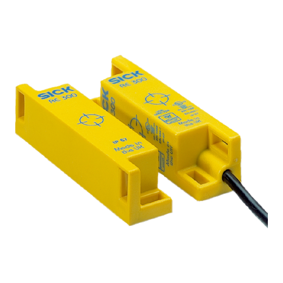
Funktionsbeschreibung Der Sicherheitssensor RE300 besteht aus # Sensor # magnetisch codiertem Betätiger # Auswerteeinheit Der Sensor wird am feststehenden Teil der Schutzeinrichtung montiert, der Betätiger am beweglichen. Beim Schließen der Schutzeinrichtung wird der Betätiger an den Sensor herangeführt. Beim Erreichen des Einschaltab- standes schaltet der Sensor.
< 4 VA (AC) Anschlussleistung max. Bemessungsspannungs- 4 kV festigkeit U Anschlussquerschnitt max. 1 x 2,5 mm Schockfestigkeit nach 30 g/11 ms IEC 68-2 27 SICK AG • Industrial Safety Systems • Deutschland • Alle Rechte vorbehalten 8 009 820/??-??-02...
Schwingungsfestigkeit 10 ... 55 Hz, Amplitude 0,35 mm ± 15 % nach IEC 68-2-6 Abfallverzögerung max. 25 ms Anzeigen LED OUTPUT, grün = Sicherheitskontak- te 13/14 und 23/24 geschlossen, LED POWER grün = Betriebsspannung ein PELV-geerdete Schutzkleinspannung. Bei Verwendung der Klemmen +/– muss die –/PE-Klemme an den Schutzleiter PE angeschlossen werden.
Inhalt Operating Instructions RE300 Maßbilder Abb. 6: Maßbild Auswerteeinheit Abb. 7: Maßbild Sensor Abb. 8: Maßbild Betätiger SICK AG • Industrial Safety Systems • Deutschland • Alle Rechte vorbehalten 8 009 820/??-??-02...
Seite 21
Contrôle périodique technique........................29 Déblocage du système en cas de défaut .....................30 Description fonctionnelle ..........................31 Caractéristiques techniques........................32 Module de contrôle ............................32 Capteur et transpondeur ..........................33 Plans cotés.................................33 SICK AG • Industrial Safety Systems • Deutschland • Alle Rechte vorbehalten 8 009 820/06-06-02...
" EN 954-1, Parties des systèmes de commandes relatives à la sécurité, annexe C " EN 1050, Sécurité des machines, Principes pour l’appréciation des risques SICK AG • Industrial Safety Systems • Deutschland • Alle Rechte vorbehalten 8 009 820/06-06-02...
Pour toute autre utilisation, aussi bien que pour les modifications – y compris concernant le montage et l’installation – la responsabilité de la société SICK AG. ne saurait être invo- quée. Par utilisation conforme aux dispositions légales on entend entre autres : "...
Tolérance de défaut d'alignement latéral (mm) Fig. 1: Positions de fonctionnement possibles, tolérance de décalage maximal en cas de montage sur un matériau non ferromagnétique, point de commutation (coupure) SICK AG • Industrial Safety Systems • Deutschland • Alle Rechte vorbehalten 8 009 820/06-06-02...
Seite 25
1 mm Fig. 2: Exemple de montage du capteur et de son actionneur Fig. 3: Exemple de montage sur une porte à charnières SICK AG • Industrial Safety Systems • Deutschland • Alle Rechte vorbehalten 8 009 820/06-06-02...
! Les câbles véhiculant des signaux d’entrée et de sortie situés à l’extérieur de l’armoire électrique doivent être installés selon les prescriptions correspondant à la catégorie de sécurité mise en oeuvre (EN 954). P. ex. câblage protégé, etc. SICK AG • Industrial Safety Systems • Deutschland • Alle Rechte vorbehalten 8 009 820/06-06-02...
Seite 27
13 23 – RESET – N Fig. 4b: Exemple de câblage en 110 ou 230 V CA avec contrôle des contacteurs commandés et réarmement statique SICK AG • Industrial Safety Systems • Deutschland • Alle Rechte vorbehalten 8 009 820/06-06-02...
! Déposer le cache jaune à l’avant. ! Mettre le sélecteur de tension sur la valeur correcte (le sélecteur est livré en position 230 V). SICK AG • Industrial Safety Systems • Deutschland • Alle Rechte vorbehalten 8 009 820/06-06-02...
Si le protecteur est rarement utilisé, le fonctionnement du capteur doit être contrôlé toutes les semaines. Régulièrement et au minimum tous les six mois, un personnel habilité doit : SICK AG • Industrial Safety Systems • Deutschland • Alle Rechte vorbehalten 8 009 820/06-06-02...
" Défaut de la liaison entre le capteur et le module de contrôle. ! Éliminer le défaut. ! Ouvrir puis refermer le protecteur. ! Effectuer le test comme indiqué au paragraphe 4.3. SICK AG • Industrial Safety Systems • Deutschland • Alle Rechte vorbehalten 8 009 820/06-06-02...
Lorsque la distance de commutation est atteinte, le capteur commute. En conséquence, les contacts de sécurité 13/14 et 23/24 du module de contrôle se ferme et le contact d’état 31/32 s’ouvre. SICK AG • Industrial Safety Systems • Deutschland • Alle Rechte vorbehalten 8 009 820/06-06-02...
PE. Si la tension d’alimentation est de110 ou 230 V CA, la borne -/PE doit être raccordé au conducteur de protection PE. SICK AG • Industrial Safety Systems • Deutschland • Alle Rechte vorbehalten 8 009 820/06-06-02...
Longueur maxi. de câble Plans cotés Fig. 5: Plan coté module de contrôle Fig. 6: Plan coté du capteur Fig. 7: Plan coté du transpondeur SICK AG • Industrial Safety Systems • Deutschland • Alle Rechte vorbehalten 8 009 820/06-06-02...
Seite 35
4.4 Cancellation of the lockout state in a fault condition ........46 Functional description ....................47 Technical data ......................48 6.1 Evaluation unit .........................48 6.2 Sensor and actuator .....................49 6.3 Dimensional drawings....................50 SICK AG • Industrial Safety Systems • Deutschland • Alle Rechte vorbehalten 8 009 820/06-06-02...
On safety This chapter deals with your own safety and the safety of the machine operators. ! Please read this chapter carefully before working with the RE300 or with machines protected by the RE300. The national/international legislative provisions regulating the use/installation, the commissioning and regular technical inspections of safety sensors apply.
" EN 1050, Safety of Machinery, Principles for Risk Assessment. Correct use The safety sensor RE300 must only be applied as defined in section 1.2 “Applications of the safety sensors”. The safety sensor must only be in- stalled by qualified personnel and only be used on the machine where it has been fitted, installed and initialised by qualified personnel and in com- pliance with these operating instructions.
! Mount evaluation unit in enclosure/switch cabinet (IP 54 minimum) on a standard 35-mm rail. Mount sensor and actuator, using the metal wash- ers supplied. SICK AG • Industrial Safety Systems • Deutschland • Alle Rechte vorbehalten 8 009 820/06-06-02...
Seite 39
Fig. 1: Possible operating positions, max. offset tolerance for installation on non-ferromagnetic materials, switch-off point Stop min. 1 mm Fig. 2: Sample assembly of sensor and actuator SICK AG • Industrial Safety Systems • Deutschland • Alle Rechte vorbehalten 8 009 820/06-06-02...
Seite 40
Installation Operating Instructions RE300 Fig. 3: Safety sensor mounted on hinged door (example) SICK AG • Industrial Safety Systems • Deutschland • Alle Rechte vorbehalten 8 009 820/06-06-02...
! The cables for the input and output signals must be routed outside the switch cabinet and in compliance with the applicable safety category (EN 954). For example: protected routing, etc. SICK AG • Industrial Safety Systems • Deutschland • Alle Rechte vorbehalten 8 009 820/06-06-02...
Seite 42
13 23 – RESET – N Fig. 4b: Example of wiring 110 V AC or 230 V AC with contactor control and static Reset SICK AG • Industrial Safety Systems • Deutschland • Alle Rechte vorbehalten 8 009 820/06-06-02...
! Remove power from RE300 evaluation unit. ! Remove yellow front panel. ! Set voltage selector to correct operating voltage (on delivery, the voltage selector is set at 230 V). SICK AG • Industrial Safety Systems • Deutschland • Alle Rechte vorbehalten 8 009 820/06-06-02...
The machine operator should carry out the following checks each day or before each shift: " safety sensor functioning properly? " no evidence of tampering? SICK AG • Industrial Safety Systems • Deutschland • Alle Rechte vorbehalten 8 009 820/06-06-02...
Seite 45
! If RESET exists, check RESET: – open Safety device – machine stops – reclose Safety device – operate START Machine must not start without RESET having been operated! SICK AG • Industrial Safety Systems • Deutschland • Alle Rechte vorbehalten 8 009 820/06-06-02...
" damage to the wiring between sensor and evaluation unit ! Correct the fault. ! Open and close the safety guard. ! Perform inspection as described in 4.3. SICK AG • Industrial Safety Systems • Deutschland • Alle Rechte vorbehalten 8 009 820/06-06-02...
When the activation distance is reached, the sensor is activated. As a result, the safety contacts 13/14 and 23/24 in the evaluation unit close and the auxiliary contacts 31/32 open. SICK AG • Industrial Safety Systems • Deutschland • Alle Rechte vorbehalten 8 009 820/06-06-02...
Rated impulse withstand voltage 4 kV Max. wire cross-section 1 x 2.5 mm Release delay max. 25 ms Shock-proof to IEC 68-2-27 30 g/11 ms SICK AG • Industrial Safety Systems • Deutschland • Alle Rechte vorbehalten 8 009 820/06-06-02...
10 ... 55 Hz, amplitude 0.35 mm ± 15 % Operating range 5 mm, S 15 mm > 17 mm/s Min. approach speed Overall resistance <75 Ω Max. cable length SICK AG • Industrial Safety Systems • Deutschland • Alle Rechte vorbehalten 8 009 820/06-06-02...
Operating Instructions RE300 Dimensional drawings Fig. 5: Dimensional drawing of control unit Fig. 6: Dimensional drawing of sensor Fig. 7: Dimensional drawing of actuator SICK AG • Industrial Safety Systems • Deutschland • Alle Rechte vorbehalten 8 009 820/06-06-02...
Seite 51
Eliminare lo stato di blocco in caso di errori ..................60 Descrizione delle funzioni .........................61 Dati tecnici..............................62 Unità di elaborazione............................62 Sensore e attuatore ............................63 Disegni quotati..............................63 SICK AG • Industrial Safety Systems • Deutschland • Alle Rechte vorbehalten 8 009 820/06-06-02...
" EN 954-1, Componenti inerenti alla sicurezza di comandi, appendice C " EN 1050, Sicurezza macchine, Valutazione dei rischi. SICK AG • Industrial Safety Systems • Deutschland • Alle Rechte vorbehalten 8 009 820/06-06-02...
Se il dispositivo viene usato per altri scopi o in caso di sue modifiche – anche in fase di montaggio o di installazione – decade ogni diritto di garanzia nei confronti della SICK AG. Per garantire l’uso secondo le norme è anche necessario "...
Tolleranza laterale di disassamento (mm) Fig. 1: posizioni possibili di funzionamento, tolleranza massima di spostamento nel montaggio su materiali non ferromagnetici, punto di spegnimento SICK AG • Industrial Safety Systems • Deutschland • Alle Rechte vorbehalten 8 009 820/06-06-02...
Seite 55
RE300 finecorsa min. 1 mm Fig. 2: Esempio di montaggio di sensore e dispositivo di azionamento Fig. 3: Esempio di montaggio su porte rototraslanti SICK AG • Industrial Safety Systems • Deutschland • Alle Rechte vorbehalten 8 009 820/06-06-02...
! Le linee dei segnali di entrata e di uscita vanno posate fuori dal quadro elettrico in conformità alla categoria di sicurezza da applicare (EN 954). P. es. posa protetta, etc. SICK AG • Industrial Safety Systems • Deutschland • Alle Rechte vorbehalten 8 009 820/06-06-02...
Seite 57
RESET – N Fig. 4b: Esempio di un cablaggio a 110 V CA o 230 V CA con controllo dei contattori e reset statico SICK AG • Industrial Safety Systems • Deutschland • Alle Rechte vorbehalten 8 009 820/06-06-02...
! Impostare l’interruttore per la selezione della tensione sulla tensione d’esercizio corret- ta (l’interruttore per la selezione della tensione viene fornito con l’impostazione per 230 V). SICK AG • Industrial Safety Systems • Deutschland • Alle Rechte vorbehalten 8 009 820/06-06-02...
" che non sia visibile nessuna manipolazione In caso di un uso generalmente raro del dispositivo di protezione va effettuta come minimo una verifica delle funzioni a settimana. SICK AG • Industrial Safety Systems • Deutschland • Alle Rechte vorbehalten 8 009 820/06-06-02...
" danno della linea di collegamento tra sensore e unità di elaborazione ! Eliminare l’errore. ! Aprire e richiudere il dispositivo di protezione. ! Effettuare la verifica come descritto in 4.3. SICK AG • Industrial Safety Systems • Deutschland • Alle Rechte vorbehalten 8 009 820/06-06-02...
Ciò comporta nell’unità di elaborazione la chiusura dei contatti di sicurezza 13/14 e 23/24 e l’apertura dei contatti ausiliari 31/32. SICK AG • Industrial Safety Systems • Deutschland • Alle Rechte vorbehalten 8 009 820/06-06-02...
Se si usa una tensione d’esercizio di 110 V CA o 230 V CA è necessario collegare al morsetto -/PE il conduttore di terra PE. SICK AG • Industrial Safety Systems • Deutschland • Alle Rechte vorbehalten 8 009 820/06-06-02...
Lunghezza massima della linea Disegni quotati Fig. 5: Disegno quotato del dispositivo di comando Fig. 6: Disegno quotato del sensore Fig. 7: Disegno quotato dell’attuatore SICK AG • Industrial Safety Systems • Deutschland • Alle Rechte vorbehalten 8 009 820/06-06-02...
Seite 64
Dati tecnici Operating Instructions RE300 SICK AG • Industrial Safety Systems • Deutschland • Alle Rechte vorbehalten 8 009 820/06-06-02...
Seite 68
+1 (952) 9 41-92 87 Representatives and agencies in all major industrial nations. SICK AG • Automatisierungstechnik • P.O. Box 310 • 79177 Waldkirch • Deutschland Phone +49 76 81 2 02 0 • Fax +49 76 81 2 02 36 09 • www.sick.com...