Emerson FSP Betriebsanleitung
Leistungsteil für drehzahlregler
Verfügbare Sprachen
Verfügbare Sprachen
Quicklinks
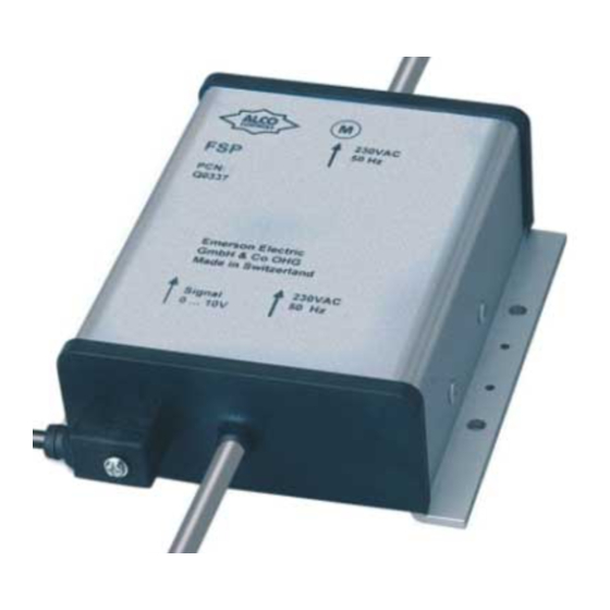
FSP Power Modules control the speed of fan
motors according to control input voltage variation
(0-10 V). Make sure that the motor is approved by
the motor/unit manufacturer for variable speed by
means of phase cutting (TRIAC).
!
Safety instructions:
• Read
installation
instructions
Failure to comply may result in device failure,
system damage or personal injury.
• It is intended for use by persons having the
appropriate knowledge and skill.
• Before opening any system make sure pressure
in system is brought to and remains at
atmospheric pressure.
• Ensure supply voltage, frequency and current
rating of motor match the rating on name plate
of FSP.
• The FSP must be grounded to earth.
• Do not touch housing if speed control is
working
because
there
temperatures.
• Attention: Disconnect mains voltage before
installation or service of fan motor and FSP!
Motor might start automatically if condensing
pressure changes.
• Maintain compliance with local electrical
regulations for wiring.
Setting:
Set points are factory-adjusted and cannot be
changed in the field.
Mounting location:
in any direction such that it stays as cool as possible:
• Avoid hot sunlight
• Good thermal contact to a cold metal surface
• Permanent air flow
FSP__65093__R06.doc
Operating Instructions
Power Module FSP
Electrical
Module:
Before wiring confirm that FSE-0xx is placed at
correct position between condenser (1) and
accumulator (2) (Fig. 3).
Use FSE-Nxx (standard applications) or FSE-Lxx
(UL-listed/low temperature) cable assemblies. Push
plugs carefully on the pins of FSP Power Module
thoroughly.
and FSE Control Module. Only one direction is
possible (see Fig. 1a and 2 for correct orientation).
Gaskets are integrated in cable assembly. Fasten
screws with 0,05 Nm.
Note: Plug can not be repaired. In case of failure
replace complete cable assembly.
Electrical connection to EC2/EC3 and other
controllers:
Use FSP-Lxx (UL-listed) cable assembly. Push
plug carefully on the pins of FSP Power Module.
Only one direction is possible (see Fig. 1a for
correct orientation). Gaskets are integrated in cable
assembly. Fasten screws with 0,05 Nm. Consult
might
be
high
controller documentation for connecting cable at
controller end.
Note: Plug can not be repaired. In case of failure
replace complete cable assembly. Connect other
end of cable with EC2/EC3 controller.
Wiring diagram (Fig. 4):
Note: Use motor fuses type/size, contactor,
thermostat and motor protection as recommended
by motor manufacturer.
Cable colour code:
1
brown
Note: The numbers refer to fig. 4 only. They are not
printed on the cable.
Replacement for 05
GB
connection
to
FSE
2
3
4
black
grey
blue
yellow/green
Emerson Electric GmbH & Co. OHG
Heerstr.111 – D-71332 Waiblingen
Tel.: 07151 509-0 - Fax.: -200
www.emersonclimate.eu
Control
Notes:
• On 3-phase motors:
- always connect neutral pin on the controller input
side
- do not connect neutral pin to the fan motor (4)
- the change of the two black wires on the
controller
input
rotating direction of the fan
• Several motors may be connected in parallel as
long as the maximum current rating is not
exceeded.
• In case of failure always replace FSP completely.
Do not try to repair or open housing.
Simple Function Test (Fig. 1b):
1. Unplug FSE conector from FSP power module;
switch power on - fan should not run.
2. Shortcircuit Pin 2 (10 V) and Pin 1 (signal input);
switch power on - fan should run with maximum
speed.
Technical Data:
• Supply voltage:
FSP-150: 230 VAC +10%/-15%, 50 Hz
FSP-180: 230 VAC +10%/-15%, 50 Hz
FSP-340: 400 VAC +10%/-15% / 3 / 50 Hz
• Operating ambient temperature range:
-20°C to +65°C
• Input Signal: 0-10 VDC
• Nominal Current:
FSP-150: 0,3 – 5 A*
FSP-180: 0,3 – 8 A*
FSP-340: 0,3 – 4 A
* Total nominal current of single phase motors
5
which use Steinmetz capacitors should not exceed
80% of these values.
• Medium compatibility: POE-, Mineral- and
Synthetic Oils
• Protection class: IP67 according to EN 60529/IEC
529
• FSP
meets
(Electromagnetic compatibility)
• Marking:
23.07.2009
side
will
change
the
EC-Directive
89/336/EC
Part No.: 861 343

Verwandte Anleitungen für Emerson FSP


Inhaltszusammenfassung für Emerson FSP
- Seite 2 FSP-180: 230V/AC +10%, -15% / 50 Hz anziehen (max. 0,05 Nm). Anschluß an Regler siehe heiß werden. Deshalb Gehäuse nicht anfassen. FSP-340: 400V/AC +10%, -15% / 3 / 50 Hz Betriebsanleitung des betreffenden Herstellers. • Achtung: Vor Installations- oder Service- •...