Pilz PU3Z Betriebsanleitung
Vorschau ausblenden
Andere Handbücher für PU3Z:
- Bedienungsanleitung (25 Seiten) ,
- Bedienungsanleitung (27 Seiten)
Inhaltsverzeichnis
Quicklinks
19 093-03
PU3Z
Sicherheitsbestimmungen
• Das Gerät darf nur von Personen
installiert und in Betrieb genommen
werden, die mit dieser Betriebsanleitung
und den geltenden Vorschriften über
Arbeitssicherheit und Unfallverhütung
vertraut sind. Beachten Sie die VDE-
sowie die örtlichen Vorschriften, insbe-
sondere hinsichtlich Schutzmaßnahmen.
• Halten Sie beim Transport, bei der
Lagerung und im Betrieb die Bedingun-
gen ein, wie sie unter "Technische Daten"
angegeben sind.
• Durch Öffnen des Gehäuses oder eigen-
mächtige Umbauten erlischt jegliche Ge-
währleistung.
• Montieren Sie das Gerät in einen
Schaltschrank; Staub und Feuchtigkeit
können sonst zu Beeinträchtigungen der
Funktionen führen.
• Sorgen Sie an allen Ausgangskontakten
bei kapazitiven und induktiven Lasten für
eine ausreichende Schutzbeschaltung.
• Verwenden Sie für die Messspannungen
L1, L1*, L2, L2*, L3, L3* und N, N* ge-
trennte Leitungen mit getrenntem Mantel.
• Verbinden Sie die Nulleiter N und N* mit
dem Erdanschluss oder dem Nulleiter des
Drehstromnetzes.
• Die Messspannungen L1 und L1*, L2 und
L2*, L3 und L3*, N und N* an getrennte
Klemmen der Anlage anschließen, so
dass durch unbeabsichtigtes Lösen einer
Klemmenschraube zumindest noch eine
Messspannung anliegt (Einfehler-
sicherheit).
Bestimmungsgemäße
Verwendung
Das Spannungsüberwachungsgerät PU3Z
dient als Einrichtung zur Überwachung von
Wechselspannungen. Das Gerät erfüllt
Forderungen der EN 945-1 bis Kategorie 4.
Es ist bestimmt für den Einsatz in
• Sicherheitsstromkreisen nach VDE 0113-
1 und EN 60204-1 (z. B. bei beweglichen
Verdeckungen)
Gerätebeschreibung
Das Spannungsüberwachungsgerät PU3Z
ist in einem P-93-Gehäuse untergebracht.
Es steht eine Variante für den Betrieb mit
Wechselspannung und eine Variante für
den Betrieb mit Gleich- und Wechsel-
spannung zur Verfügung.
Merkmale:
• Relaisausgänge: drei Sicherheitskontakte
(Schließer) und ein Hilfskontakt (Öffner),
zwangsgeführt
• 6 Halbleiterausgänge
• redundanter Messkreis
• Ruhestromprinzip
• Messbereich: 110 ... 600 V AC bzw. 64 ...
346 V AC gegen den Nulleiter
• automatischer oder manueller Start
• Statusanzeige
• Rückführkreis zur Überwachung externer
Schütze
Safety Regulations
• The unit may only be installed and
operated by personnel who are familiar
with both these instructions and the
current regulations for safety at work and
accident prevention. Follow VDE and local
regulations especially as regards
preventative measures.
• Transport, storage and operating
conditions should all conform to the
standards as stated under "Technical
details".
• Any guarantee is void following opening of
the housing or unauthorised
modifications.
• The unit should be panel mounted,
otherwise dampness or dust could lead to
function impairment.
• Adequate fuse protection must be
provided on all output contacts with
capacitive and inductive loads.
• Use three separately sheathed leads with
the measured voltages L1, L1*, L2, L2*,
L3, L3* und N, N*.
• Connect the neutral N and N* with the
earth connection or connect with the
neutral on the three phase supply.
• The measured voltages L1 und L1*, L2
und L2*, L3 und L3*, N und N*must be
connected on separate terminals so if a
screw becomes loose there will always
still be at least one voltage connected (
fail safe principle)
Authorised Applications
The Voltage Monitoring Relay PU3Z is a
device for monitoring a.c. voltages. The unit
meets requirements of EN 954-1 up to
category 4. The PU3Z is for use in:
• Safety Circuits according to VDE 0113-1
and EN 60204-1 (e.g. with movable
guards).
Description
The PU3Z is enclosed in P-93 housing.
There are is one version available for AC
operation and one for AC/DC operation.
Features:
• Relay outputs: 3 safety contacts (N/O)
and one auxiliary contact (N/C), positive-
guided.
• 6 Semi-conductor outputs.
• Redundant measuring circuit
• Fail safe principle.
• Measuring range: 110 ... 600 V AC/64 ...
346 V AC against the neutral
• Automatic or manual restart.
• Status Indicators.
• Feedback Control Loop for monitoring of
external contactors/relays.
The relay complies with the following safety
requirements:
• The circuit is redundant with built-in self-
monitoring.
- 1 -
Conseils préliminaires
• La mise en oeuvre de l'appareil doit être
effectuée par une personne spécialisée
en installations électriques, en tenant
compte des prescriptions des différentes
normes applicables (NF, EN, VDE...)
notamment au niveau des risques
encourus en cas de défaillance de
l'équipement électrique.
• Pour le transport, le stockage et
l'utilisation, respectez les exigences des
normes specifiées (voir „Caractéristiques
techniques").
• L'ouverture de l'appareil ou sa modifi-
cation annule automatiquement la
garantie.
• L'appareil doit être monté dans une ar-
moire; l'humidité et la poussière pouvant
entraîner des aléas de fonctionnement.
• Vérifiez que le pouvoir de coupure des
contacts de sortie est suffisant en cas de
circuits capacitifs ou inductifs.
• Utilisez pour les entrées mesure L1, L1*,
L2, L2*, L3, L3* et N, N* des liaisons
séparées blindées.
• Reliez les bornes N et N* à la borne de
terre ou au neutre du réseau triphasé.
• Reliez les bornes L1 et L1*, L2 et L2*,
L3 et L3*, N et N* à des endroits
différents de l'installation, pour garantir,
en cas de coupure accidentelle d'une
ligne, qu'une tension de mesure reste
présente sur l'appareil (sécurité garantie
en cas de défaut).
Domaines d'utilisation
Le PU3Z est une relais de tension destiné à
surveiller un réseau triphasé alternatif.
L'appareil satisfait aux exigences de
l'EN 954-1 jusqu'en catégorie 4. Le PU3Z
est adapté pour :
• les circuits de sécurité selon les normes
NF 79-130 et EN 60-204-1 (ex.
protecteurs mobiles).
Description de l'appareil
Inséré dans un boîtier P-93, le PU3Z est
disponible en une version pour la tension
d'alimentation alternative et une version en
alimentation continue et alternative.
Autres particularités :
• Sorties disponibles : 3 contacts à
fermeture de sécurité et un contact à
ouverture pour signalisation
• 6 sorties statiques
• Circuit mesure redondant
• Indication du défaut par retombée du
relais de sortie
• Plage de mesure : 110 ... 600 V AC ou
64 ... 346 V AC par rapport au neutre
• Réarmement automatique ou manuel
• LEDs de visualisation
• Boucle de retour pour l'auto-contrôle des
contacteurs externes
Inhaltsverzeichnis

Verwandte Anleitungen für Pilz PU3Z


Inhaltszusammenfassung für Pilz PU3Z
- Seite 1 Authorised Applications Domaines d’utilisation Bestimmungsgemäße The Voltage Monitoring Relay PU3Z is a Le PU3Z est une relais de tension destiné à Verwendung device for monitoring a.c. voltages. The unit surveiller un réseau triphasé alternatif. Das Spannungsüberwachungsgerät PU3Z meets requirements of EN 954-1 up to L’appareil satisfait aux exigences de...
-
Seite 2: Funktionsbeschreibung
Function Description Description du fonctionnement Das Spannungsüberwachungsgerät PU3Z The voltage monitor PU3Z operates as a Le relais de tension PU3Z est un relais à arbeitet als Schwellwertschalter. Die Schalt- threshold switch. The switching threshold of seuil. Les seuils de déclenchement fixes... - Seite 3 Der Zustand des Messkreises wird durch die The status of the measuring circuit will be L'état du circuit de mesure est visualisé par Halbleiterausgänge Y41 ... Y46 und die displayed by the semiconductor outputs Y41 les sorties statiques Y41 ... Y46 et par les zugehörigen LEDs angezeigt: to Y46 and the corresponding LED's: LEDs correspondantes :...
-
Seite 4: Montage
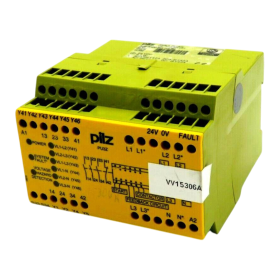
Betriebsarten Operating Modes Modes de fonctionnement • Automatischer Start: Gerät ist aktiv, • Automatic reset: Unit is active as soon as • Réarmement automatique : le relais est sobald die Versorgungsspannung anliegt, the operating voltage is applied, the input activé dès que la tension d'alimentation der Eingangskreis geschlossen ist und circuit closed and all voltages are under est appliquée si le circuit d'entrée est... - Seite 5 Eingangskreis (Y4- Y5) geschlossen ist. Anwendung Application Utilisation Y41 Y42 Y43 Y44 Y45 Y46 24V 0V FAULT L1 L1* L2 L2* PU3Z VL1-L2 (Y41) POWER VL2-L3 (Y42) SYSTEM VL1-L3 (Y43) FAULT* VL1-N (Y44) VOLTAGE VL2-N (Y45)
- Seite 6 - 6 -...
- Seite 7 Technische Daten Technical details Caractéristiques techniques Versorgungsspannung U Supply voltage U Tension d’alimentation U 120 ... 240 V AC/DC AC/DC AC/DC 24 V Spannungstoleranz U Voltage tolerance U Plage de la tension d'alimentation U -15 %/+10 % Leistungsaufnahme bei U Power consumption at U Consommation pour U 12,0 VA...
-
Seite 8: Eg-Konformitätserklärung
Die vollständige EG-Konformitätserklärung The complete EC Declaration of Conformity Vous trouverez la déclaration de finden Sie im Internet unter www.pilz.com is available on the Internet at www.pilz.com conformité CE complète sur notre site Bevollmächtigter: Norbert Fröhlich, Authorised representative: Norbert internet www.pilz.com Pilz GmbH &... - Seite 9 Descripción del dispositivo Descrizione Apparaatbeschrijving El dispositivo de supervisión de tensión PU3Z Il dispositivo di controllo tensioni PU3Z è Het spanningsbewakingsrelais PU3Z is in está montado dentro de una carcasa P-93. inserito in un alloggiamento P-93. Per il een P-93-behuizing ondergebracht.
- Seite 10 Descripción del funcionamiento Descrizione del funzionamento Functiebeschrijving El dispositivo de supervisión de tensión PU3Z Il dispositivo di controllo tensioni PU3Z Het spanningsbewakingsrelais PU3Z werkt trabaja como interruptor de valor umbral. Los funziona come interruttore di soglia. Le als drempelwaardeschakelaar. De schakel- umbrales lógicos de las tensiones trifásicas...
- Seite 11 El estado del circuito de medición se indica Lo stato del circuito di misura viene De toestand van het meetcircuit wordt via mediante las salidas por semiconductor visualizzato attraverso le uscite a semi- de halfgeleideruitgangen Y41 ... Y46 en de Y41 ...
- Seite 12 Error interno o rotura de conductor/ Errore interno o rottura di un cavo/ Fig. 2: Diagrama de impulsos/Diagramma impulsi/Impulsdiagram Interne fout of draadbreuk Puesta en marcha Messa in funzione Ingebruikneming Al poner en marcha el dispositivo hay que Alla messa in funzione occorre osservare: Neem bij ingebruikneming het volgende in tener en cuenta: •...
- Seite 13 • Circuito de rearme • Circuito di avvio • Startcircuit - Rearme automático: puentear S33-S34 - Start automatico: cavallottare S33-S34. - Automatische start: S33-S34 verbinden. - Rearme manual: Conectar contacto de - Start manuale: collegare il contatto di - Handmatige start: Startcontact op rearme a S33-S34.
- Seite 15 Datos técnicos Dati tecnici Technische gegevens Tensión de alimentación U Tensione di alimentazione U Voedingsspanning U 120 ... 240 V AC/DC AC/DC AC/DC 24 V Tolerancia de tensión U Tolleranza di tensione U Spanningstolerantie U -15 %/+10 % Consumo de energía con U Potenza assorbita con U Opgenomen vermogen bij U 12,0 VA...
- Seite 16 CE è disponibile in Internet Gevolmachtige: Norbert Fröhlich, web de Internet www.pilz.com all’indirizzo www.pilz.com Pilz GmbH & Co. KG, Felix-Wankel-Str. 2, Apoderado: Norbert Fröhlich, Mandatario: Norbert Fröhlich, 73760 Ostfildern, Duitsland Pilz GmbH & Co. KG, Felix-Wankel-Str. 2, Pilz GmbH &...