Gemü 536 Original Einbau- Und Montageanleitung
Sitzventil
Vorschau ausblenden
Andere Handbücher für 536:
- Original einbau- und montageanleitung (36 Seiten) ,
- Originalmontageanleitung (24 Seiten) ,
- Original einbau- und montageanleitung (32 Seiten)

Verwandte Anleitungen für Gemü 536


Inhaltszusammenfassung für Gemü 536
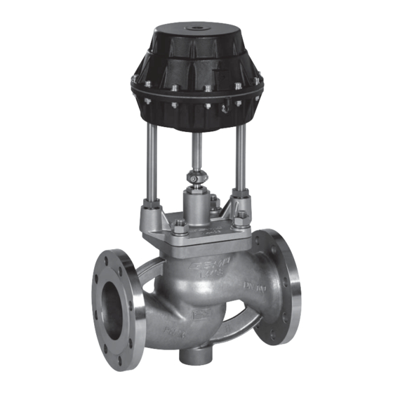
- Seite 1 Sitzventil Metall, DN 65 - 150 Globe Valve Metal, DN 65 - 150 ORIGINAL EINBAU- UND MONTAGEANLEITUNG INSTALLATION, OPERATING AND MAINTENANCE INSTRUCTIONS...
-
Seite 2: Inhaltsverzeichnis
Inhaltsverzeichnis Allgemeine Hinweise Voraussetzungen für die einwandfreie Allgemeine Hinweise Funktion des GEMÜ-Ventils: Allgemeine Sicherheitshinweise 2 Sachgerechter Transport und Lagerung Hinweise für Service- Installation und Inbetriebnahme durch und Bedienpersonal eingewiesenes Fachpersonal Warnhinweise Bedienung gemäß dieser Einbau- und Verwendete Symbole Montageanleitung Begriff sbestimmungen Ordnungsgemäße Instandhaltung Vorgesehener Einsatzbereich Auslieferungszustand... -
Seite 3: Warnhinweise
Gefährdung von Personen durch Warnhinweise sind dabei immer mit elektrische, mechanische und chemische einem Signalwort und teilweise auch Einwirkungen. mit einem gefahrenspezifischen Symbol Gefährdung von Anlagen in der gekennzeichnet. Umgebung. Folgende Signalwörter bzw. Versagen wichtiger Funktionen. Gefährdungsstufen werden eingesetzt: Gefährdung der Umwelt durch Austreten GEFAHR gefährlicher Stoff... -
Seite 4: Begriff Sbestimmungen
Das Ventil darf nicht in Vorgesehener explosionsgefährdeten Zonen Einsatzbereich verwendet werden. Das 2/2-Wege-Geradsitzventil GEMÜ 536 ist für den Einsatz in Auslieferungszustand Rohrleitungen konzipiert. Es steuert ein Das GEMÜ-Ventil wird als separat durchfl ießendes Medium indem es durch verpacktes Bauteil ausgeliefert. - Seite 5 Steuerfunktion 1 Steuerfunktion 2 Steuerfunktion 3 Betriebs- Steuer- Antriebs- Betriebs- Steuer- Antriebs- Betriebs- Steuer- Antriebs- Gewicht Gewicht Gewicht druck druck größe druck druck größe druck druck größe Werte [kg] [kg] [kg] [bar] Code [bar] Code [bar] Code [m³/h] 12,0 3,0 - 7,0 25,0 4,5 - 7,0 40,0...
-
Seite 6: Bestelldaten
Qualitatives Kv-Wert Diagramm Regelkrone gleichprozentig modifiziert 10 20 30 40 50 60 70 80 90 100 Hub [%] Das Diagramm gibt den ungefähren Regelkrone (Regelventil) Verlauf der Kv-Wert Kurve wieder. Bestelldaten Gehäuseform Code Steuerfunktion Code Durchgangskörper Federkraft geschlossen (NC) Federkraft geöffnet (NO) Anschlussart Code... -
Seite 7: Lieferung Und Leistung
Werkzeug benutzen. Montage und Anschluss Funktionsbeschreibung Vor Einbau: Das fremdgesteuerte 2/2 Wege-Ventil Ventilkörperwerkstoff und Sitzdichtung GEMÜ 536 ist ein Metall-Geradesitzventil entsprechend Betriebsmedium auslegen. mit Durchgangskörper und besitzt Eignung vor Einbau prüfen! einen wartungsarmen Membranantrieb. Siehe Kapitel 6 "Technische Daten". - Seite 8 Einbaulage: WARNUNG Wir empfehlen eine senkrecht stehende Haube steht unter Federdruck! oder hängende Einbaulage des Antriebs ® Gefahr von schwersten Verletzungen zur Optimierung der Standzeit. oder Tod! Richtung des Betriebsmediums: Antrieb nicht öff nen. Durchfl ussrichtung: WARNUNG Aggressive Chemikalien! ® Verätzungen! Montage nur mit geeigneter Schutzausrüstung.
-
Seite 9: Steuerfunktionen
2. Flansche vor Verschrauben sorgfältig Steuer- ausrichten. funktion 1 3. Dichtungen gut zentrieren. 4. Alle Flanschbohrungen nutzen. 5. Ventilfl ansch und Rohrfl ansch mit geeignetem Dichtmaterial und passenden Schrauben verbinden (Dichtmaterial und Schrauben sind nicht im Lieferumfang enthalten). Anschluss 2 Schrauben über Kreuz anziehen! Steuer - funktion 2 + 3... -
Seite 10: Montage / Demontage Von Ersatzteilen
Montage / Demontage eindrehen und mit geeignetem Werkzeug über Kreuz festziehen. von Ersatzteilen Siehe auch Kapitel 11.1 "Montage des Ventils" und Kapitel 20 "Schnittbild und Ersatzteile". 5. Antrieb A in Geschlossen-Position 12.1 Demontage Antrieb bringen, komplett montiertes Ventil auf und Dichtring 43 Funktion und auf Dichtheit prüfen. -
Seite 11: Inspektion Und Wartung
Reinigung: Der Betreiber muss regelmäßige Betreiber der Anlage ist verantwortlich für Sichtkontrollen der Ventile entsprechend Auswahl des Reinigungsmediums und den Einsatzbedingungen und des Durchführung des Verfahrens. Gefährdungspotenzials zur Vorbeugung von Undichtheit und Beschädigungen durchführen. Ebenso muss das Ventil in Inspektion und Wartung entsprechenden Intervallen demontiert und auf Verschleiß... -
Seite 12: Demontage Zur Entsorgung
Rücksendung 16.1 Demontage zur Entsorgung Ventil reinigen. WARNUNG Rücksendeerklärung bei GEMÜ anfordern. Haube steht unter Federdruck! Rücksendung nur mit vollständig ® Gefahr von schwersten Verletzungen ausgefüllter Rücksendeerklärung. oder Tod! Antrieb nur mit einer geeigneten Presse Ansonsten erfolgt keine öff nen. Gutschrift bzw. -
Seite 13: Fehlersuche / Störungsbehebung
Fehlersuche / Störungsbehebung Fehler Möglicher Grund Fehlerbehebung Steuermedium entweicht aus Entlüftung (Anschluss Antrieb austauschen und Steuermedium auf 4* bei Steuerfunktion NC / Steuermembrane* undicht Verschmutzungen untersuchen Anschluss 2* bei Steuerfunktion NO) Steuermedium entweicht Antrieb austauschen und Steuermedium auf Spindelabdichtung undicht aus Antriebsspindel* Verschmutzungen untersuchen Medium entweicht an... -
Seite 14: Schnittbild Und Ersatzteile
Schnittbild und Ersatzteile Anschluss 4 / Entlüftung bei Steuerfunktion Steuermembrane Anschluss 2 / Entlüftung bei Steuerfunktion Antriebsspindel Überwurfmutter Antriebsflansch Ventilkörperflansch Ventilspindel Pos. Benennung Bestellbezeichnung Ventilkörper K 536... Sitzdichtung Dichtring 536...SVS... Sechskantmutter Zylinderschraube Antrieb 9536... Tellerscheibe 14 / 32... -
Seite 15: Einbauerklärung
23.05.2014 Projektnummer: SV-Pneum-2014-05 Handelsbezeichnung: Typ 536 Es wird erklärt, dass die folgenden grundlegenden Anforderungen der Maschinenrichtlinie 2006/42/EG erfüllt sind: 1.1.3.; 1.1.5.; 1.1.7.; 1.2.1.; 1.3.; 1.3.2.; 1.3.3.; 1.3.4.; 1.3.7.; 1.3.9.; 1.5.3.; 1.5.5.; 1.5.6.; 1.5.7.; 1.5.8.; 1.5.9.; 1.6.5.; 2.1.1.; 3.2.1.; 3.2.2.; 3.3.2.; 3.4.4.; 3.6.3.1.; 4.1.2.1.; 4.1.2.3.; 4.1.2.4.; 4.1.2.5.; 4.1.2.6. a);... -
Seite 16: Eu-Konformitätserklärung
GEMÜ Gebr. Müller Apparatebau GmbH & Co. KG Fritz-Müller-Straße 6-8 D-74653 Ingelfingen erklären, dass unten aufgeführte Armaturen die Sicherheitsanforderungen der Druckgeräte- richtlinie 2014/68/EU erfüllen. Benennung der Armaturen - Typenbezeichnung Sitzventil GEMÜ 536 Benannte Stelle: TÜV Rheinland Industrie Service GmbH Nummer: 0035 Zertifikat-Nr.: 01 202 926/Q-02 0036... - Seite 32 GEMÜ Gebr. Müller Apparatebau GmbH & Co. KG · Fritz-Müller-Str. 6-8 · D-74653 Ingelfi ngen-Criesbach Telefon +49(0)7940/123-0 · Telefax +49(0)7940/123-192 · info@gemue.de · www.gemu-group.com...