Gemü 532 Original Einbau- Und Montageanleitung
Sitzventil
Vorschau ausblenden
Andere Handbücher für 532:
- Original einbau- und montageanleitung (44 Seiten) ,
- Montageanleitung (16 Seiten) ,
- Originalmontageanleitung (16 Seiten)

Verwandte Anleitungen für Gemü 532


Inhaltszusammenfassung für Gemü 532
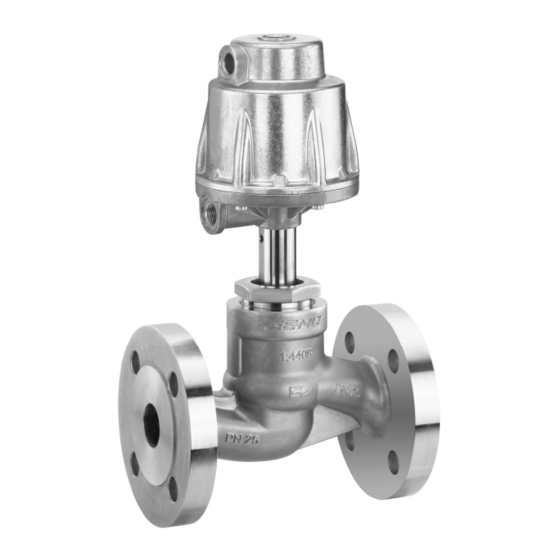
- Seite 1 Sitzventil Metall, DN 15 - 100 Globe Valve Metal, DN 15 - 100 ORIGINAL EINBAU- UND MONTAGEANLEITUNG INSTALLATION, OPERATING AND MAINTENANCE INSTRUCTIONS...
-
Seite 2: Inhaltsverzeichnis
Inhaltsverzeichnis Schnittbilder und Ersatzteile 20.1 DN 15 - 50 Allgemeine Hinweise 20.2 DN 65 - 100 Allgemeine Sicherheitshinweise 2 Einbauerklärung Hinweise für Service- EU-Konformitätserklärung und Bedienpersonal Allgemeine Hinweise Warnhinweise Verwendete Symbole Voraussetzungen für die einwandfreie Sicherheitshinweis am Produkt Funktion des GEMÜ-Ventils: Begriff... -
Seite 3: Hinweise Für Service
Hinweise für Service- Warnhinweise und Bedienpersonal Warnhinweise sind, soweit möglich, nach folgendem Schema gegliedert: Die Einbau- und Montageanleitung enthält SIGNALWORT grundlegende Sicherheitshinweise, die bei Inbetriebnahme, Betrieb und Instandhaltung Art und Quelle der Gefahr zu beachten sind. Nichtbeachtung kann zur ® Mögliche Folgen bei Nichtbeachtung. Folge haben: Maßnahmen zur Vermeidung der Gefahr. -
Seite 4: Sicherheitshinweis Am Produkt
Steuerfunktion Mögliche Betätigungsfunktionen des Ventils. Sicherheitshinweis am Vorgesehener Produkt Einsatzbereich Das 2/2-Wege-Ventil GEMÜ 532 ist für den Einsatz in Rohrleitungen konzipiert. Es steuert ein durchfl ießendes Medium Antrieb steht unter Federdruck Actuator under spring pressure Actionneur sous pression par ressort indem es durch ein Steuermedium geschlossen oder geöff... - Seite 5 Maximal zulässige Sitz Leckrate Sitzdichtung Norm Prüfverfahren Leckrate Prüfmedium PTFE DIN EN 12266-1 Luft Metall DIN EN 12266-1 Luft Nenn- Max. Betriebsdruck [bar] Steuerdruck [bar] weite Stf. 1 Federkraft geschlossen (NC) Stf. 1 Federkraft geschlossen (NC) Werte Antriebs- Antriebs- Antriebs- Antriebs- Antriebs- größe 0...
-
Seite 6: Bestelldaten
Druck- / Temperatur-Zuordnung für Geradsitz-Ventilkörper Zulässige Betriebsdrücke in bar bei Temperatur in °C* Anschluss- Werkstoff- Code Code 16,0 16,0 14,5 13,4 12,7 11,8 25,0 25,0 22,7 21,0 19,8 18,5 40,0 40,0 36,3 33,7 31,8 29,7 19,0 16,0 14,8 13,6 12,0 10,2 16,0 16,0... - Seite 7 Medien um "Wasserschläge" zu vermeiden Baulänge EN 558, Reihe 1 ISO 5752, basic series 1 ** Nur Steuerfunktion NC Flansch ANSI Class 125/150 RF, GEMÜ 532 GEMÜ 532 Baulänge EN 558, Reihe 1, Antriebe 0, 1, 2 Antriebe 3, 4...
-
Seite 8: Herstellerangaben
Werkzeug benutzen. Umweltschutzbestimmungen entsorgen. Funktionsbeschreibung Lieferung und Leistung Das pneumatisch gesteuerte 2/2-Wege- Ware unverzüglich bei Erhalt auf Geradsitzventil GEMÜ 532 verfügt über Vollständigkeit und Unversehrtheit einen robusten wartungsarmen Aluminium- überprüfen. Kolbenantrieb. Sitzdichtungen und Lieferumfang aus Versandpapieren, Ventilkörper sind gemäß Datenblatt in Ausführung aus Bestellnummer... -
Seite 9: Montage Und Anschluss
Montage und Anschluss Montagearbeiten nur durch geschultes Fachpersonal. Geeignete Schutzausrüstung gemäß Vor Einbau: den Regelungen des Anlagenbetreibers Eignung Ventilkörper- und Dichtwerkstoff berücksichtigen. entsprechend Betriebsmedium prüfen. Siehe Kapitel 6 "Technische Daten". Installationsort: 11.1 Montage des Ventils VORSICHT WARNUNG Ventil äußerlich nicht stark Unter Druck stehende Armaturen! beanspruchen. -
Seite 10: Steuerfunktionen
Die Durchfl ussrichtung ist durch einen 6. Nur Verbindungselemente aus Pfeil auf dem Ventilkörper gekennzeichnet: zulässigen Werkstoff en verwenden! Entsprechende Vorschriften für Anschlüsse beachten! Nach der Montage: Alle Sicherheits- und Schutzeinrichtungen wieder anbringen bzw. in Funktion setzen. gegen den Teller mit dem Teller 11.2 Steuerfunktionen... -
Seite 11: Steuermedium Anschließen
11.3 Steuermedium anschließen Wichtig: Steuermediumleitungen spannungs- und knickfrei Steuermedium- montieren! anschluss 2 Je nach Anwendung geeignete Anschlussstücke verwenden. Steuerfunktion 1 Gewinde der Steuermediumanschlüsse 2 und 4: G1/4 Steuerfunktion Anschlüsse Federkraft geschlossen 2: Steuermedium (Öffnen) (NC) Steuermedium- anschluss 4 Federkraft 4: Steuermedium (Schließen) geöffnet (NO) Beidseitig 2: Steuermedium (Öffnen) -
Seite 12: Montage / Demontage Von Ersatzteilen
Montage / Demontage 4. Sitzdichtung 14 entnehmen. 5. Alle Teile reinigen, dabei nicht zerkratzen von Ersatzteilen oder beschädigen. Siehe auch Kapitel 11.1 "Montage des 6. Neue Sitzdichtung 14 einlegen. Ventils" und Kapitel 20 "Schnittbilder und 7. Geeignetes Schraubensicherungsmittel Ersatzteile". auf Gewinde von Spindel b auftragen. 12.1 Demontage Antrieb 8. -
Seite 13: Montage Antrieb
13. Tellerscheibe 19 einlegen und mit 12.3.1 DN 15 - 50 Zylinderschrauben 39 fi xieren. 1. Antrieb A in Off en-Position bringen. 14. Sicherungsblech 38 auf Ventilteller 15 2. Antrieb 360° drehbar. Position der legen. Steuermediumanschlüsse beliebig. 15. Kompletten Ventilteller 15 an 3. -
Seite 14: Inbetriebnahme
Inbetriebnahme VORSICHT Wartungs- und WARNUNG Instandhaltungstätigkeiten nur durch Aggressive Chemikalien! geschultes Fachpersonal. ® Verätzungen! Für Schäden welche durch Vor Inbetriebnahme Dichtheit unsachgemäße Handhabung oder der Medienanschlüsse Fremdeinwirkung entstehen, übernimmt GEMÜ keinerlei Haftung. prüfen! Nehmen Sie im Zweifelsfall vor Dichtheitsprüfung nur mit Inbetriebnahme Kontakt mit GEMÜ... -
Seite 15: Entsorgung
Entsorgung VORSICHT Alle Ventilteile Zu starker Pressdruck! entsprechend den ® Bruchgefahr des Antriebsoberteils 10. Entsorgungsvorschriften / Nur minimal nötigen Druck Umweltschutzbestimmungen ausüben. entsorgen. Auf Restanhaftungen und Ausgasung von eindiff undierten Medien achten. 16.1 Demontage zur Entsorgung für Steuerfunktion 1 WARNUNG Antriebsoberteil 10 steht unter Federdruck! ®... -
Seite 16: Demontage Zur Entsorgung Für Steuerfunktion
16.2 Demontage zur Entsorgung für Steuerfunktion 2 1. Antrieb A demontieren (siehe Kapitel 12.1 "Demontage Antrieb"). 2. Verbindungssschrauben 23 zwischen Antriebsoberteil 10 und Antriebsunterteil 25 lösen und entfernen. 16.3 Demontage zur Entsorgung für Steuerfunktion 3 1. Antrieb A demontieren (siehe Kapitel 12.1 "Demontage Antrieb"). -
Seite 17: Rücksendung
Rücksendung Hinweise Ventil reinigen. Hinweis zur Rücksendeerklärung bei GEMÜ Mitarbeiterschulung: anfordern. Zur Mitarbeiterschulung nehmen Rücksendung nur mit vollständig Sie bitte über die Adresse auf der ausgefüllter Rücksendeerklärung. letzten Seite Kontakt auf. Ansonsten erfolgt keine Im Zweifelsfall oder bei Missverständnissen Gutschrift bzw. keine ist die deutsche Version des Dokuments Erledigung der Reparatur ausschlaggebend! -
Seite 18: Fehlersuche / Störungsbehebung
Fehlersuche / Störungsbehebung Fehler Möglicher Grund Fehlerbehebung Steuermedium entweicht aus Entlüftungsbohrung (Anschluss 4* bei Antrieb austauschen und Steuermedium auf Steuerkolben undicht Steuerfunktion NC / Verschmutzungen untersuchen Anschluss 2* bei Steuerfunktion NO) Steuermedium entweicht Antrieb austauschen und Steuermedium auf Spindelabdichtung undicht aus Leckagebohrung* Verschmutzungen untersuchen Betriebsmedium entweicht... -
Seite 19: Schnittbilder Und Ersatzteile Dn
Schnittbilder und Ersatzteile 20.1 DN 15 - 50 GEMÜ 532 mit Sitzdichtung aus PTFE Anschluss 4 / Entlüftungsbohrung bei Steuerfunktion 1 Anschluss 2 / Entlüftungsbohrung bei Steuerfunktion 2 Leckagebohrung Pos. Benennung Bestellbezeichnung Ventilkörper K534... Dichtring 534...SVS... Sitzdichtung Antrieb 9532 Überwurfmutter... -
Seite 20: Sitzdichtung Aus Stahl
20.2 DN 65 - 100 GEMÜ 532 mit Sitzdichtung aus Stahl Anschluss 4/ Entlüftungsbohrung bei Steuerfunktion 1 Anschluss 2/ Entlüftungsbohrung bei Steuerfunktion 2 Leckagebohrung Pos. Benennung Bestellbezeichnung Ventilkörper K 534... Dichtring Sechskantmutter Sitzdichtung 530...SVS... Dichtring Zylinderschraube Antrieb 9530 Überwurfmutter Spindel... -
Seite 21: Einbauerklärung
29.12.2009 Projektnummer: SV-Pneum-2009-12 Handelsbezeichnung: Typ 532 Es wird erklärt, dass die folgenden grundlegenden Anforderungen der Maschinenrichtlinie 2006/42/EG erfüllt sind: 1.1.3.; 1.1.5.; 1.1.7.; 1.2.1.; 1.3.; 1.3.2.; 1.3.3.; 1.3.4.; 1.3.7.; 1.3.9.; 1.5.3.; 1.5.5.; 1.5.6.; 1.5.7.; 1.5.8.; 1.5.9.; 1.6.5.; 2.1.1.; 3.2.1.; 3.2.2.; 3.3.2.; 3.4.4.; 3.6.3.1.; 4.1.2.1.; 4.1.2.3.; 4.1.2.4.; 4.1.2.5.; 4.1.2.6. a); 4.1.2.6. b);... -
Seite 22: Eu-Konformitätserklärung
GEMÜ Gebr. Müller Apparatebau GmbH & Co. KG Fritz-Müller-Straße 6-8 D-74653 Ingelfingen erklären, dass unten aufgeführte Armaturen die Sicherheitsanforderungen der Druckgeräte- richtlinie 2014/68/EU erfüllen. Benennung der Armaturen - Typenbezeichnung Sitzventil GEMÜ 532 Benannte Stelle: TÜV Rheinland Industrie Service GmbH Nummer: 0035 Zertifi kat-Nr.: 01 202 926/Q-02 0036... - Seite 44 GEMÜ Gebr. Müller Apparatebau GmbH & Co. KG · Fritz-Müller-Str. 6-8 · D-74653 Ingelfi ngen-Criesbach Telefon +49(0)7940/123-0 · Telefax +49(0)7940/123-192 · info@gemue.de · www.gemu-group.com...