Kapitel
Inhaltsverzeichnis

Inhaltszusammenfassung für Gemü 532 SKS
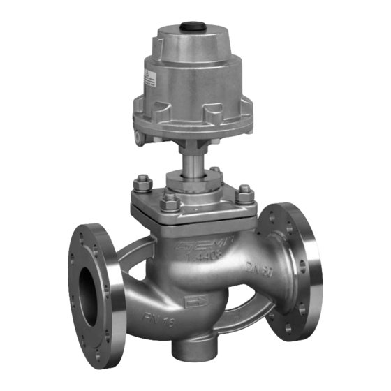
- Seite 1 532 SKS Austausch des Ersatzteil-Sets SKS Steuerfunktion 1, DN 65 - 100 Replacement of spare parts kit SKS Control function 1, DN 65 - 100 ORIGINAL MONTAGEANLEITUNG ASSEMBLY INSTRUCTIONS 532 SKS...
-
Seite 2: Inhaltsverzeichnis
Ventil nicht als Trittstufe oder Aufstiegshilfe benutzen! ® Gefahr des Abrutschens / der Beschädigung des Ventils. VORSICHT Maximal zulässigen Druck nicht überschreiten! ® Eventuell auftretende Druckstöße (Wasserschläge) durch Schutzmaßnahmen vermeiden. Einbau- und Montageanleitung GEMÜ 532 beachten! 532 SKS 2 / 24... -
Seite 3: Bestelldaten
Antriebsgröße (Code) Bestandteile Ersatzteil-Set SKS Pos. Stück Benennung Spindel Sicherungsring Dichtring Führungsbuchse Sechskantmutter Druckfeder Stützring V-Manschette (bei Antriebsgröße 2 Stück) Druckring Sechskantmutter Kolbenlaufbuchse Sitzdichtung Ventilteller Nietstift Tellerscheibe Lippenring AD O-Ring O-Ring Lippenring ID Dichtring V-Manschette 532 SKS 3 / 24... -
Seite 4: Geräteaufbau
Geräteaufbau Entlüftungs- bohrung Steuermedium- anschluss 2 Leckagebohrung Geräteaufbau GEMÜ 532 Steuerfunktion 1 (DN 65 - 100) 532 SKS 4 / 24... - Seite 5 Tellerscheibe Antriebskolben Lippenring AD O-Ring Verbindungsschrauben (6x) O-Ring Antriebsunterteil Lippenring ID Sitzfl ansch Dichtring Druckfeder (bei Antriebsgröße 2 ab DN 50) Überwurfmutter Sicherungsblech Zylinderschrauben Anzeigespindel Verschlussstopfen Antrieb Überwurfmutter Sicherungsring Führungsbuchse Druckfeder Stützring V-Manschette Druckring V-Manschette 532 SKS 5 / 24...
-
Seite 6: Demontage
(nur Originalteile von GEMÜ verwenden). 1. Antrieb A in Off en-Position bringen. 2. Sechskantmuttern 6 lösen. 3. Antrieb A und Sitzfl ansch 29 vom Ventilkörper 1 entfernen. 4. Antrieb A von Steuermediumleitungen trennen. 5. Dichtring 30 entnehmen. 532 SKS 6 / 24... - Seite 7 VORSICHT Zu starker Pressdruck! ® Bruchgefahr des Antriebsoberteils 10. Nur minimal nötigen Druck ausüben. 5. Verbindungssschrauben 23 zwischen Antriebsoberteil 10 und Antriebsunterteil 25 lösen und entfernen. 6. Presskraft langsam reduzieren. 7. Antriebsoberteil 10 entnehmen. 532 SKS 7 / 24...
-
Seite 8: Auswechseln Des Ersatzteil-Sets Sks
Dichtring Sechskantmutter Sechskantmutter Kolbenlaufbuchse Lippenring AD O-Ring O-Ring Lippenring ID Dichtring Zylinderschraube Sicherungsring Führungsbuchse Druckfeder Stützring V-Manschette (bei Antriebsgröße 2 Stück) Druckring V-Manschette Spindel Sitzdichtung Ventilteller Nietstift Tellerscheibe Die Spindel-Baugruppe wird schon komplett montiert ausgeliefert. 532 SKS 8 / 24... -
Seite 9: Auswechseln Des Ersatzteil-Sets
29. Antriebsoberteil 10 montieren (siehe bei Antriebsgröße 2) Kapitel 7.1 "Montage Antriebsoberteil"). • Elastomer 30. Neuen Dichtring 4 in Ventilkörper 1 • PTFE einlegen. • Elastomer 31. Antrieb A montieren (siehe Kapitel 7.2 • PTFE "Montage Antrieb auf Ventilkörper"). 532 SKS 9 / 24... -
Seite 10: Montage
Antriebsoberteil 10 und Antriebsunterteil 25 achten. 3. Antrieb A mit geeigneter Presse 7. Verschlussstopfen SA2 in Antrieb A verspannen. einschrauben. VORSICHT Zu starker Pressdruck! ® Bruchgefahr des Antriebsoberteils 10. Nur minimal nötigen Druck ausüben. 532 SKS 10 / 24... -
Seite 11: Montage Antrieb Auf Ventilkörper
5. Auf Übereinstimmung der Lochbilder von Sitzfl ansch 29 und Ventilkörper 1 achten. 6. Sechskantmuttern 6 über Kreuz festziehen. 7. Antrieb A in Geschlossen-Position bringen. 8. Komplett montiertes Ventil auf Funktion und auf Dichtheit prüfen. 532 SKS 11 / 24... -
Seite 12: General Information
® This entails the risk of slipping-off or damaging the valve. CAUTION Do not exceed the maximum permissible pressure! ® Take precautionary measures to avoid possible pressure surges (water hammer). Observe the GEMÜ 532 installation, operating and maintenance instructions! 532 SKS 12 / 24... -
Seite 13: Order Data
Compression spring Support ring Chevron packing (piece with actuator size 2) Pressure ring Hexagon nut Piston sleeve Seat seal Valve plug Retaining nut Lip ring external sealing O-ring O-ring Lip ring internal sealing Gasket Chevron packing 532 SKS 13 / 24... -
Seite 14: Construction
Construction Vent hole Control medium connector 2 Leak detection hole GEMÜ 532 construction control function 1 (DN 65-100) 532 SKS 14 / 24... - Seite 15 Compression spring (with actuator size 2 from DN 50) Union nut Locking plate Cylindrical screws Indicator spindle Sealing plug Actuator Union nut Circlip Guide bush Compression spring Support ring Chevron packing Pressure ring Chevron packing 532 SKS 15 / 24...
-
Seite 16: Disassembly
1. Move the actuator A to the open position. 2. Undo the hexagon nut 6. 3. Remove the actuator A and seat fl ange 29 from the valve body 1. 4. Disconnect the actuator A from control medium lines. 5. Remove gasket 30. 532 SKS 16 / 24... - Seite 17 ® Risk of breakage of actuator top 10. Only use minimum required pressure. 5. Undo and remove the connecting bolts 23 between the actuator top 10 and actuator base 25. 6. Slowly reduce pressing force. 7. Remove actuator top 10. 532 SKS 17 / 24...
-
Seite 18: Replacement Of Spare Parts Kit Sks
Gasket Cylindrical screw Circlip Guide bush Compression spring Support ring Chevron packing (piece with actuator size 2) Pressure ring Chevron packing Spindle Seat seal Valve plug Retaining nut The spindle subassembly is supplied fully assembled. 532 SKS 18 / 24... -
Seite 19: Replacement Of The Spare Parts Kit
31. Mount actuator A (see chapter 7.2 tightness. "Actuator mounting on the valve body"). Layout of chevron packings: • PTFE (not included with actuator size 2) • Elastomer • PTFE • Elastomer • PTFE 532 SKS 19 / 24... - Seite 20 3. Tension actuator A using a suitable 7. Screw sealing plug SA2 into actuator A. press. CAUTION Applied pressure too high! ® Risk of breakage of actuator top 10. Only use minimum required pressure. 532 SKS 20 / 24...
- Seite 21 fl ange 29 and valve body 1 are aligned. 6. Tighten the hexagon nut 6 diagonally. 7. Move the actuator A to the closed position. 8. With the valve fully assembled, check that it is working correctly and that it is leak-tight. 532 SKS 21 / 24...
- Seite 22 532 SKS 22 / 24...
- Seite 23 532 SKS 23 / 24...
- Seite 24 GEMÜ Gebr. Müller Apparatebau GmbH & Co. KG · Fritz-Müller-Str. 6-8 · D-74653 Ingelfi ngen-Criesbach Telefon +49(0)7940/123-0 · Telefax +49(0)7940/123-192 · info@gemue.de · www.gemu-group.com...


