Herunterladen Inhalt Inhalt Diese Seite drucken

Werbung

Verfügbare Sprachen
  • DE

Verfügbare Sprachen

  • DEUTSCH, seite 1
Big Spender
Bierzapfanlage
Beer Dispenser
Dispensador de cerveza
Tireuse à bière
Spillatore per birra
10031955 10031956

Werbung

Inhaltsverzeichnis
loading

Inhaltszusammenfassung für Klarstein 10031955

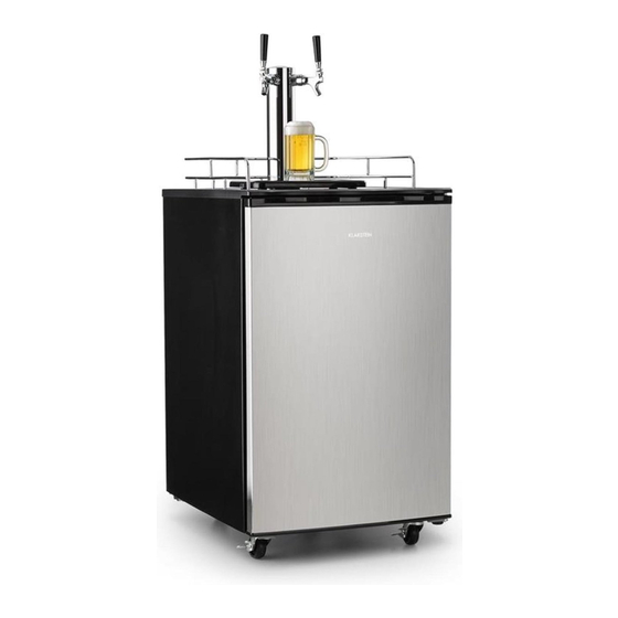
  • Seite 1 Big Spender Bierzapfanlage Beer Dispenser Dispensador de cerveza Tireuse à bière Spillatore per birra 10031955 10031956...
  • Seite 3: Inhaltsverzeichnis

    Installation des CO2-Reglers 10 Koppler mit Fass verbinden 13 Bedienung 14 Reinigung und Pflege 15 Hinweise zur Entsorgung 16 TECHNISCHE DATEN Artikelnummer 10031955, 10031956 Stromversorgung 220-240 V ~ 50-60 Hz KONFORMITÄTSERKLÄRUNG Hersteller: Chal-Tec GmbH, Wallstraße 16, 10179 Berlin, Deutschland. Dieses Produkt entspricht den folgenden Europäischen...
  • Seite 4: Sicherheitshinweise

    SICHERHEITSHINWEISE • Benutzen Sie das Gerät nur für den genannten Zweck und halten sie sich genau an die Angaben in der Bedienungsanleitung. • Bevor Sie das Gerät benutzen, müssen alle Teile genau wie in der Anleitung beschrieben installiert werden. Halten Sie sich genau an die Installationsanleitung. •...
  • Seite 5 Besondere Hinweise • Achten Sie bei der Positionierung des Gerätes darauf, dass das Netzkabel nicht eingeklemmt oder beschädigt ist. • Achten Sie darauf, dass sich keine Mehrfachsteckdosen oder Netzteile auf der Rückseite des Geräts befi nden. Um eine Kontamination von Lebensmitteln zu vermeiden, beachten Sie bitte die folgenden Anweisungen: •...
  • Seite 6: Geräteteile

    GERÄTETEILE Fass-Koppler Schutzschiene Rückfluss-Stopper Tropfwannenaufsatz Gummidichtung Tropfwanne CO2 Rückfluss-Stopper Gummifüße Zapfturmdichtung Zylinder-Basisplatte Zapfturn mit Zubehör Metallscheiben Doppelter Messregler Rollen mit Bremse Hochdruckdichtung Rollen ohne Bremse CO2-Zylinder (nicht im Band für den CO2-Tank Lieferumfang enthalten)
  • Seite 7 Luftschlauch-Flügelmutter Schlüssel für den Messregler Luftschlauch Obere Zapfturm-Abdeckung Luftschlauchdichtung Zusatz-Dichtungen Bierhahn-Schlüssel Dichtungen und O-Ringe Sie werden feststellen, dass die meisten O-Ringe und Unterlegscheiben bereits an Ihrer Zapfanlage befestigt sind. Die Zapfanlage enthält jedoch einen zusätzlichen Dichtungssatz mit Unterlegscheiben und O-Ringen, für zukünftigen Ersatz und Wartung. Richten Sie sich beim Ersetzen der Dichtungen nach dem folgenden Diagramm: Koppler-Unterseite Koppler-Unterseite...
  • Seite 8: Standort Und Geeignete Fässer

    STANDORT UND GEEIGNETE FÄSSER Hinweise zum Standort • Um sicherzustellen, dass das Gerät mit maximaler Effizienz arbeitet, lassen Sie um das Gerät herum genug Platz, damit die Luft ausreichend zirkulieren kann. • Stellen Sie das Gerät an einem möglichst kühlen Ort auf, an dem es nicht in direktem Sonnenlicht steht und an dem es weit entfernt von Wärmequellen, wie Öfen oder Heizungen ist.
  • Seite 9: Zusammenbau

    ZUSAMMENBAU Lesen Sie sich die Anleitung für den Zusammenbau sorgfältig durch. Wenn Sie unsicher sind, lassen Sie das Gerät von einem qualifizierten Fachmann zusammenbauen. WICHTIG: Lassen Sie das Gerät vor dem Anschluss und Zusammenbau 8 Stunden lang aufrecht stehen. Wenn das Gerät liegend Transport wurde braucht das Gerät Zeit, damit sich das Kühlmittel verteilen wieder kann.
  • Seite 10: Installation Des Co2-Reglers

    So installieren Sie die Zapfsäule Setzen Sie die Zapfsäule oben auf die Anlage und leiten Sie den Bierkanal in das Kühlgehäuse. Richten Sie die Nasen an der Zapfsäule an den Löchern im Verschlussring aus und stellen Sie die Zapfsäule aufrecht hin. Drehen Sie die Zapfsäule 1/4 Umdrehung im Uhrzeigersinn, während Sie sie gleichzeitig herunterdrücken, bis sie einrastet.
  • Seite 11 Manche Modelle Schritt 3: werden mit einer Stecken Sie Schutzkappe den CO2 auf dem Rückfluss- Verbindungsstück Stopper in den geliefert. Entfernen Koppler. Sie sie vom Koppler, bevor Sie mit Schritt 3 Fortfahren. Schritt 5: Schritt 4: Wählen Sie eine der Verbinden Sie den CO2- drei Rückfluss-Stopper Schlauch mit dem Koppler.
  • Seite 12 Zuordnung und korrekte Installation der Dichtungen und O-Ringe Dichtungen an der Koppler-Unterseite O-Ringe an der CO2-Leitung CO2-Leitung CO2-Leitung O-Ring für O-Ring für zum Regler zum Koppler den Koppler den Regler Dichtung zwischen CO2 Tank-Band Zapfturm und Kühlgehäuse O-Ring für den Zapfhahn...
  • Seite 13: Koppler Mit Fass Verbinden

    KOPPLER MIT FASS VERBINDEN Versichern Sie sich, dass der schwarze Hebel am Koppler geschlossen (oben) ist, bevor Sie den Koppler am Fass anbringen (Bild 1). Stecken Sie den Koppler in den Verriegelungshals oben am Bierfass und drehen Sie ihn mit einer 1/4 Drehung im Uhrzeigersinn fest (Bild 2).
  • Seite 14: Bedienung

    BEDIENUNG Prüfen Sie vor der Benutzung die Spannung auf der Geräteplakette und schließen Sie das an eine Steckdose an, die der Spannung des Geräts entspricht. Stellen Sie die Tropfwanne unter den Zapfhahn an der Zapfsäule, um überschüssiges Bier aufzufangen. Öffnen Sie den Zapfhahn, indem Sie ihn zu sich hinziehen und zapfen Sie Bier ab. HINWEIS: Falls kein Bier aus dem Hahn kommt, gehen Sie die einzelnen Schritte des letzen Kapitels noch einmal durch und überprüfen Sie ob alle Teile korrekt installiert wurden.
  • Seite 15: Reinigung Und Pflege

    REINIGUNG UND PFLEGE So reinigen Sie Koppler und Bierkanal Sie zuerst die CO2-Zufuhr komplett ab. Lösen Sie dazu den CO2-Schlauch vom Kuppler und zapfen Sie Bier, bis kein Bier mehr aus dem Hahn kommt. Dadurch wird der Druck im Fass freigegeben, so dass der Koppler sicher abgelöst werden kann.
  • Seite 16: Hinweise Zur Entsorgung

    Pflege und Lagerung Stellen Sie den Temperaturregler im Kühlgehäuse auf die Position OFF, bevor Sie das Netzkabel herausziehen. Dieses Gerät verfügt nicht über eine aktive Abtaufunktion, daher kann sich während dem Betrieb etwas Eis im Kühlgehäuse bilden. Lassen Sie das Eis abtauen und verwenden Sie keine scharfen oder Spitzen Gegenstände um das Eis zu entfernen.
  • Seite 17: Technical Data

    Installing Keg Tap 27 Operation 28 Care and Cleaning 29 Hints on Disposal 30 TECHNICAL DATA Item number 10031955, 10031956 Power supply 220-240 V ~ 50-60 Hz DECLARATION OF CONFORMITY Producer: Chal-Tec GmbH, Wallstraße 16, 10179 Berlin, Germany. This product is conform to the following European...
  • Seite 18: Safety Instructions

    SAFETY INSTRUCTIONS • Use this appliance only for its intended purpose as descnbed in this operation manual. • This appliance must be properly installed in accordance with the installation instructions before it is used. See the installation section for more details. •...
  • Seite 19 Special Notes • When positioning the unit, make sure that the power cord is not pinched or damaged. • Make sure that there are no multiple sockets or power supplies on the back of the unit. To avoid contamination of food, please follow the instructions below: •...
  • Seite 20: Parts Description

    PARTS DESCRIPTION Keg Coupler Guard Rail Bacl Flow Stopper Drip Pan Top Rubber Washer Drip Pan Rubber Directional Washer Rubber Foot Beer Tower Washer Keg Base Board Beer Towe Tap Assembly Metal Washer Dual Gauge Regulator Caster with Brake High Pressure Washer Caster CO2 Tank (not included in the CO2 Tank Strap...
  • Seite 21 Sir Hose Wing Nut Washer Regulator Wrench Air Hose Beer Tower Hole Cover Air Hose Connector Washer Extra Washers Beer Tap Wrench Washers and O-rings You will find that most 0-rings and Washers are already attached to your product. In your product you will notice an extra seal kit with washers and O-rings, this is for future replacements and maintenance, use the diagram below to he]p you with replacing your seals.
  • Seite 22: Location And Compatible Keg Types

    LOCATION AND COMPATIBLE KEG TYPES Proper Location • To ensure that your product works to the maximum efficiency it was designed for, keep it in a location where there is proper air circulation and electrical outlets. • Choose a location where the product will be away from heat and will not be exposed to direct sunlight •...
  • Seite 23: Assembly

    ASSEMBLY Read assembly instructions carefully to ensure that you understand all installation instructions before installing the product. If after completing the process you are still unsure whether the product has been properly installed, we recommend that you contact a qualified installer. IMPORTANT: Allow the product to stand in an upright position for at least 8 hours before plugging in the unit.
  • Seite 24: Co2 Regulator Installation

    Beer Tower Installation Place the Beer Tower on the top of the product and run the beer line into the fridge. Line up the notches on the Beer Tower with the holes in the locking ring and stand the tower upright. Twist clockwise 1/4 turn while pressing down firmly to lock the tower in place.
  • Seite 25 Some units may Step 3: come with this The CO2 attachment. It rubber is not needed directional and should be washer goes removed from into the the coupler prior coupler. to Step 3. Step 5: Step 4: Put one of Connect the CO2 the backflow line from the regulator to...
  • Seite 26 Washers and O-rings Washers on the coupler O-rings on the CO2 line CO2 line CO2 line O-ring O-ring for to regulator to coupler for coupler regulator Tap tower washer CO2 tank band between refrigerator and tap tower O-ring for tap...
  • Seite 27: Installing Keg Tap

    INSTALLING KEG TAP Make sure the black pull handle of the tap is in the closed (up) position before installing it on the keg (Fig. 1 - below). Insert the keg coupler into the locking neck of the beer keg and turn clockwise ¼ to lock it into position (Fig. 2 - below). This means that it is secured to the keg.
  • Seite 28: Operation

    OPERATION Check the voltage on the equipment label before use. Only connect the device to sockets that correspond to the voltage of the device. If you are unsure whether your connections meet the requirements, consult an electrician or your electricity supplier. Place the drip tray under the beer faucet to avoid messes from excess beer.
  • Seite 29: Care And Cleaning

    CARE AND CLEANING Flushing the tubes Turn off CO2 completely before attempting to clean. First, turn off the CO2 and dispense beer until it stops. This will release pressure in the keg so that the coupler can safely be detached. Remove the hose from the coupler and carefully twist the dispenser faucet off of the top of the product.
  • Seite 30: Hints On Disposal

    Storage & Care Please adjust the temperature control dial inside of the cabinet to the OFF position before unplugging your cord. This unit does not self-defrost and ice may build up inside the unit. To avoid permanent damage to the unit, never use sharp objects inside the product.
  • Seite 31: Datos Técnicos

    Unir el acoplador al barril 41 Utilización 42 Limpieza y cuidado 43 Retirada del aparato 44 DATOS TÉCNICOS Número de artículo 10031955, 10031956 Suministro eléctrico 220-240 V ~ 50-60 Hz DECLARACIÓN DE CONFORMIDAD Fabricante: Chal-Tec GmbH, Wallstraße 16, 10179 Berlín (Alemania). Este producto cumple con las siguientes directivas...
  • Seite 32: Indicaciones De Seguridad

    INDICACIONES DE SEGURIDAD • Utilice este aparato solamente para el fin para el cual ha sido concebido y siga los pasos del manual de instrucciones. • Antes de utilizar el aparato, debe instalar todas las piezas tal y como se indica en el manual.
  • Seite 33 Notas especiales • Cuando coloque la unidad, asegúrese de que el cable de alimentación no esté pellizcado ni dañado. • Asegúrese de que no haya varias tomas o fuentes de alimentación en la parte posterior de la unidad. Para evitar la contaminación de los alimentos, siga las siguientes instrucciones: •...
  • Seite 34: Piezas Del Aparato

    PIEZAS DEL APARATO Acoplador del barril Rail de protección Tapón de reflujo Accesorio de la bandeja antigoteo Junta de goma Bandeja antigoteo Tapón de reflujo de CO2 Patas de goma Junta del dispensador Placa base del cilindro Columna de dispensación con Arandela de metal accesorios Regulador medidor doble...
  • Seite 35 Tuerca de mariposa del conducto Llave del regulador de medición de aire Conducto de aire Cubierta superior de la columna del dispensador Junta del conducto de aire Juntas adicionales Llave del grifo Juntas y juntas tóricas Se dará cuenta de que la mayoría de las juntas tóricas y arandelas ya están fijadas en su dispensador.
  • Seite 36: Ubicación Y Barriles Adecuados

    UBICACIÓN Y BARRILES ADECUADOS Indicaciones para la ubicación • Para asegurarse de que el aparato trabaja con la mayor eficiencia posible, deje suficiente distancia alrededor del mismo para que el aire pueda circular correctamente. • Coloque el aparato en un lugar lo más fresco posible en el que no se vea expuesto a la luz directa del sol y alejado de fuentes de calor, como hornos o radiadores.
  • Seite 37: Montaje

    MONTAJE Lea atentamente estas indicaciones de seguridad sobre el montaje. Si tiene dudas, contacte con un especialista para su montaje. IMPORTANTE: Coloque el aparato en posición vertical durante 8 horas antes de conectarlo al suministro eléctrico. Si el aparato se ha transportado de manera horizontal, este necesitará...
  • Seite 38: Instalación Del Regulador De Co2

    Cómo instalar el grifo del dispensador Conecte el grifo en la parte superior y dirija el canal de la cerveza hacia la carcasa de refrigeración. Oriente los salientes del grifo hacia los orificios de la anilla de sellado y coloque el grifo en posición vertical.
  • Seite 39 Algunos modelos se Paso 3: entregan con una Conecte el tapa de protección tapón de en el conector. Retire reflujo de CO2 dicha protección al acoplador. del acoplador antes de continuar con el paso 3. Paso 5: Paso 4: Seleccione uno de los Conecte el conducto de tres tapones de reflujo CO2 al acoplador.
  • Seite 40 Orden e instalación correcta de las juntas y juntas tóricas Juntas en la parte inferior del acoplador Juntas tóricas en el conducto de CO2 Conducto CO2 hacia Conducto CO2 hacia Junta tórica para Junta tórica para el regulador el acoplador el acoplador el regulador Junta: entre el...
  • Seite 41: Unir El Acoplador Al Barril

    UNIR EL ACOPLADOR AL BARRIL Asegúrese de que la palanca negra del acoplador esté cerrada (parte superior) antes de montar el acoplador al barril (imagen 1). Encaje el acoplador al cuello del cierre situado en la parte superior del barril y gírelo 1/4 de vuelta en el sentido de las agujas del reloj (imagen 2).
  • Seite 42: Utilización

    UTILIZACIÓN Antes de utilizar el aparato, compruebe la tensión en la placa técnica del mismo y conecte el aparato solamente a tomas de corriente que se adecuen a dicha tensión. Coloque la bandeja antigoteo bajo el grifo del dispensador para recoger la cerveza que se vierta.
  • Seite 43: Limpieza Y Cuidado

    LIMPIEZA Y CUIDADO Cómo limpiar el acoplador y el canal de cerveza Desmonte completamente el conducto de CO2. Suelte el conducto de CO2 del acoplador y dispense la cerveza hasta que ya no salga más del grifo. Así se liberará la presión del barril para poder quitar el acoplador con seguridad.
  • Seite 44: Retirada Del Aparato

    Cuidado y almacenamiento Coloque el regulador de temperatura de la carcasa de refrigeración en la posición OFF antes de desconectar el cable de alimentación. Este aparato no dispone de una función de descongelación activa, por lo que es posible que se forme hielo en la carcasa de refrigeración durante el funcionamiento.
  • Seite 45: Fiche Technique

    Relier le coupleur au fût 55 Utilisation 56 Nettoyage et entretien 57 Conseils pour le recyclage 58 FICHE TECHNIQUE Numéro d’article 10031955, 10031956 Alimentation 220-240 V ~ 50-60 Hz DÉCLARATION DE CONFORMITÉ Fabricant : Chal-Tec GmbH, Wallstraße 16, 10179 Berlin, Allemagne. Ce produit est conforme aux directives européennes...
  • Seite 46: Consignes De Sécurité

    CONSIGNES DE SÉCURITÉ • Utilisez l’appareil exclusivement aux fins prévues et tenez-vous en strictement aux indications du mode d’emploi. • Avant d’utiliser l’appareil, tous les éléments doivent d’abord être installés exactement comme il est indiqué dans le guide. Tenez-vous en strictement au guide d’installation.
  • Seite 47 Remarques particulières • Lors du positionnement de l‘appareil, assurez-vous que le cordon d‘alimentation n‘est pas pincé ou endommagé. • Assurez-vous qu‘il n‘y a pas de prises multiples ou d‘alimentations multiples à l‘arrière de l‘appareil. Pour éviter la contamination des aliments, veuillez suivre les instructions ci-dessous : •...
  • Seite 48: Composants De L'appareil

    COMPOSANTS DE L’ APPAREIL Coupleur de fût Rails de protection Anti-retour Accessoire du bac d’égouttage Joint caoutchouc Bac d’égouttage Anti retour de CO² Pieds en caoutchouc Joint de colonne Socle de base des cylindres Colonne avec accessoires Rondelles métalliques Double manomètre de réglage Roulettes avec freins Joint haute pression Roulettes sans freins...
  • Seite 49 Ecrou papillon du tuyau d’air Clé du manomètre Tuyau d’air Couvercle de la colonne supérieure Joint du tuyau d’air Joints supplémentaires Clé du robinet à bière Joints et joints toriques Vous remarquerez que la plupart des joints toriques et rondelles sont déjà installés sur votre tireuse à...
  • Seite 50: Emplacement Et Fûts Adaptés

    EMPLACEMENT ET FÛTS ADAPTÉS Consignes concernant l’emplacement • Pour être sûr que l’appareil fonctionne avec la meilleure efficacité, laissez suffisamment d’espace autour de l’appareil pour que l’air puisse circuler librement. • Placez l’appareil dans un lieu aussi frais que possible et à l’abri de l’ensoleillement direct et loin des sources de chaleur telles que les fours ou les radiateurs.
  • Seite 51: Assemblage

    ASSEMBLAGE Lisez bien le guide d’assemblage en entier. Si vous avez un doute, faites assembler l’appareil par un professionnel. IMPORTANT : Avant de le brancher ou de l’assembler, laissez l’appareil reposer à la verticale pendant 8 heures. Si l’appareil a été transporté couché, ‘appareil a besoin de ce temps pour que le fluide réfrigérant puisse se répartir de nouveau.
  • Seite 52: Installation Du Manomètre De Co²

    Comment installer la colonne à pression Placez la colonne au-dessus de la tireuse et passez le canal à bière dans le compartiment réfrigérant. Dirigez les pattes de la colonne vers les trous de l’anneau de verrouillage et placez-y la colonne verticalement. Tournez la colonne d’un 1/4 de tour en sens horaire en l’enfonçant en même temps jusqu’à...
  • Seite 53 Quelques modèles Etape 3 : sont livrés avec Branchez l’anti- une capsule de reflux à CO² protection sur le sur le coupleur. branchement. Retirez-le du coupleur avant de poursuivre vers l’étape 3. Etape 5: Etape 4: Choisissez un des trois Reliez le tuyau de CO²...
  • Seite 54 Ordre et méthode d’installation correcte des joints et joints toriques Joints sur la partie inférieure du coupleur Joint torique sur la conduite de CO² Conduite de CO² Conduite de CO² Joint torique Joint torique pour vers le manomètre vers le coupleur pour le coupleur le manomètre Joint entre la colonne...
  • Seite 55: Relier Le Coupleur Au Fût

    RELIER LE COUPLEUR AU FÛT Assurez-vous que le levier noir soit sur le coupleur soit fermé (en haut), avant de monter le coupleur sur le fût (schéma 1). Enfoncez le coupleur dans la gorge de verrouillage en haut du fût à bière et serrez-le d’un 1/4 de tour en sens horaire (schéma 2).
  • Seite 56: Utilisation

    UTILISATION Avant l’utilisation, contrôlez la tension sur la plaque signalétique de l‘appareil et branchez-le sur une prise dont la tension correspond à celle de l’appareil. Placez le bac d’égouttage sous le robinet à pression de la colonne pour récupérer la bière qui déborde. Ouvrez le robinet à...
  • Seite 57: Nettoyage Et Entretien

    NETTOYAGE ET ENTRETIEN Nettoyage du coupleur et du canal à bière Retirez d’abord complètement l’alimentation en CO². Pour cela dévissez le tuyau de CO² du coupleur et tirez de la bière jusqu’à ce que plus rien ne sorte du robinet. Cela libère la pression dans le fût, afin que vous puissiez desserrer le coupleur en toute sécurité.
  • Seite 58: Conseils Pour Le Recyclage

    Entretien et stockage Mettez le bouton de réglage de a température à l’intérieur du compartiment réfrigérateur sur OFF avant de débranchez le câble d’alimentation. Cet appareil n’est pas équipé d’une fonction de dégivrage active, il se peut donc qu’il se forme un peu de givre à...
  • Seite 59: Dati Tecnici

    Collegare l´accoppiatore al barile 69 Utilizzo  70 Pulizia e manutenzione 71 Smaltimento 72 DATI TECNICI Articolo numero 10031955, 10031956 Alimentazione 220-240 V ~ 50-60 Hz DICHIARAZIONE DI CONFORMITA Produttore: Chal-Tec GmbH, Wallstraße 16, 10179 Berlino, Germania. Questo prodotto è conforme alle seguenti direttive...
  • Seite 60: Avvertenze Di Sicurezza

    AVVERTENZE DI SICUREZZA • Usare il dispositivo solo per lo scopo previsto e attenersi alle istruzioni contenute nel presente manuale. • Prima di utilizzare il dispositivo per la prima volta, installare i componenti come descritto nel presente manuale di istruzioni. Attenersi alle istruzioni di installazione e utilizzo.
  • Seite 61 Note speciali • Quando si posiziona l‘unità, assicurarsi che il cavo di alimentazione non sia schiacciato o danneggiato. • Assicurarsi che non vi siano prese multiple o alimentatori sul retro dell‘unità. Per evitare la contaminazione degli alimenti, seguire le seguenti istruzioni: •...
  • Seite 62: Componenti

    COMPONENTI Accoppiatore barile Binari di protezione Valvola antiriflusso Accessorio raccogligocce Guarnizione in gomma Vaschetta raccogligocce Valvola antiriflusso CO2 Piedi in gomma Guarnizione colonna Piastra base cartuccia Colonna con accessori Dischi in metallo Regolatore doppio Rotelline con freno Guarnizione pressione Rotelline senza freno Cartuccia CO2 (non è...
  • Seite 63 Dado tubo aria Chiave per regolatore Tubo aria Coperchio colonna Guarnizione tubo aria Ulteriori guarnizioni Chiave rubinetto Guarnizioni e anelli La maggior parte degli anelli e delle rondelle sono già assemblati allo spillatore. Tuttavia lo spillatore contiene un kit supplementare con rondelle e anelli per la sostituzione e la manutenzione future.
  • Seite 64: Installazione E Barili Idonei

    INSTALLAZIONE E BARILI IDONEI Note sull´installazione • Per garantire il corretto funzionamento del dispositivo, lasciare attorno ad esso spazio libero sufficiente per la circolazione dell´aria. • Posizionare il dispositivo in un luogo fresco lontano dalla luce diretta del sole e da fonti di calore come stufe o termosifoni.
  • Seite 65: Assemblaggio

    ASSEMBLAGGIO Leggere attentamente le istruzioni per l´assemblaggio. In caso di dubbi, far assemblare il dispositivo da un tecnico qualificato. IMPORTANTE: prima dell´installazione e del montaggio, lasciare il dispositivo per 8 ore in posizione verticale. Se il dispositivo è stato trasportato in posizione orizzontale, è...
  • Seite 66: Installazione Del Regolatore Co2

    Installare la colonna Posizionare la colonna sulla parte superiore dello spillatore e condurre il canale della birra nell’unità di raffreddamento. Allineare i fori sulla colonna ai fori sull‘anello di bloccaggio e mettere la colonna in posizione verticale. Ruotare la colonna di 1/4 in senso orario premendola fino all´incastro. INSTALLAZIONE DEL REGOLATORE CO2 Attenersi alla procedura seguente per installare il regolatore CO2.
  • Seite 67 Alcuni modelli Fase 3: sono dotati di un Inserire la valvola tappo protettivo antiriflusso CO2 sul componente nell´accoppiatore. di collegamento. Rimuovere il tappo dall´accoppiatore prima di procedere con la fase 3. Fase 5: Fase 4: Selezionare una Collegare il tubo CO2 valvola antiriflusso all´accoppiatore.
  • Seite 68 Corretta installazione delle guarnizioni e degli anelli Guarnizioni sulla parte inferiore dell´accoppiatore Anelli sul tubo CO2 Tubo per il Tubo CO2 per Anello per Anello per il regolatore CO2 l´accoppiatore l´accoppiatore regolatore Guarnizione tra la Banda colonna e l’unità di serbatoio CO2 raffreddamento Anello per il rubinetto...
  • Seite 69: Collegare L´accoppiatore Al Barile

    COLLEGARE L´ACCOPPIATORE AL BARILE Assicurarsi che la levetta nera sull´accoppiatore (in alto) sia chiusa prima di installare l´accoppiatore al barile (figura 1). Inserire l‘accoppiatore nel blocco sulla parte superiore del barile e ruotarlo di 1/4 in senso orario (figura 2). Assicurarsi che l‘accoppiatore sia ben fissato al barile.
  • Seite 70: Utilizzo

    UTILIZZO Prima dell´uso controllare la tensione sulla targhetta identificativa e collegare il dispositivo ad una presa che corrisponde alla tensione indicata. Collocare la vaschetta raccogligocce sotto il rubinetto per raccogliere la birra in eccesso. Aprire il rubinetto tirandolo verso di sé e spillare la birra. NOTA: se la birra non esce dal rubinetto, rivedere le fasi descritte nella sezione precedente e verificare che tutti i componenti siano stati installati correttamente.
  • Seite 71: Pulizia E Manutenzione

    PULIZIA E MANUTENZIONE Pulire l´accoppiatore e il canale della birra Spegnere completamente l´immissione di CO2 prima della pulizia. Rimuovere il tubo CO2 dall´accoppiatore e spillare la birra fino a quando non esce più dal rubinetto. In questo modo la pressione viene rilasciata nel barile e l´accoppiatore può...
  • Seite 72: Smaltimento

    Manutenzione e conservazione Prima di scollegare il cavo di alimentazione, posizionare su OFF il termostato posto sull’unità di raffreddamento. Questo dispositivo non è dotato di una funzione di sbrinamento attiva quindi durante l´uso può formarsi del ghiaccio nell’unità di raffreddamento. Far scongelare il ghiaccio e non usare oggetti taglienti per rimuovere il ghiaccio.

Diese Anleitung auch für:

10031956Big spender

Inhaltsverzeichnis