Gemü 565 Original Einbau- Und Montageanleitung
Vorschau ausblenden
Andere Handbücher für 565:
- Betriebsanleitung (20 Seiten) ,
- Betriebsanleitung (36 Seiten)

Verwandte Anleitungen für Gemü 565


Inhaltszusammenfassung für Gemü 565
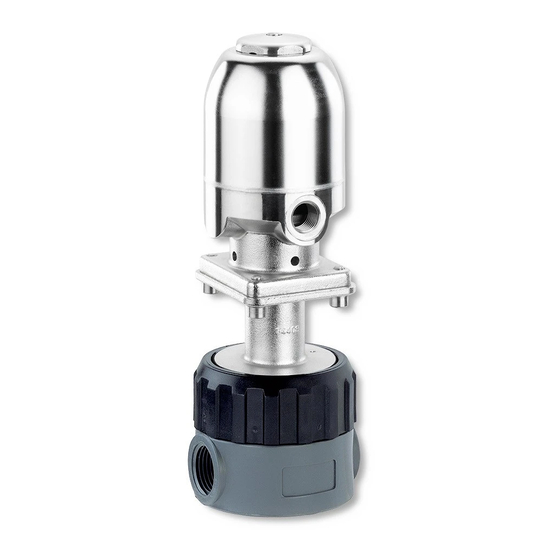
- Seite 1 Regelventil Kunststoff / Metall, DN 3 - 15 Control Valve Plastic / Metal, DN 3 - 15 ORIGINAL EINBAU- UND MONTAGEANLEITUNG INSTALLATION, OPERATING AND MAINTENANCE INSTRUCTIONS...
-
Seite 2: Inhaltsverzeichnis
Inhaltsverzeichnis Allgemeine Hinweise Voraussetzungen für die einwandfreie Allgemeine Hinweise Funktion des GEMÜ-Ventils: Allgemeine Sicherheitshinweise 2 Sachgerechter Transport und Lagerung. Hinweise für Service- Installation und Inbetriebnahme durch und Bedienpersonal eingewiesenes Fachpersonal. Warnhinweise Bedienung gemäß dieser Einbau- und Verwendete Symbole Montageanleitung. Begriff sbestimmungen Ordnungsgemäße Instandhaltung. -
Seite 3: Hinweise Für Service
Hinweise für Service- Warnhinweise und Bedienpersonal Warnhinweise sind, soweit möglich, nach folgendem Schema gegliedert: Die Einbau- und Montageanleitung enthält grundlegende Sicherheitshinweise, die bei SIGNALWORT Inbetriebnahme, Betrieb und Instandhaltung zu beachten sind. Nichtbeachtung kann zur Art und Quelle der Gefahr Folge haben: ®... -
Seite 4: Verwendete Symbole
Vorgesehener Verwendete Symbole Einsatzbereich Gefahr durch heiße Oberfl ächen! Das 2/2-Wege-Regelventil GEMÜ 565 ist für den Einsatz in Rohrleitungen Gefahr durch ätzende Stoff e! konzipiert. Es steuert ein durchfl ießendes Medium indem es durch ein Steuermedium geschlossen oder Hand: Beschreibt allgemeine geöff... -
Seite 5: Technische Daten
Technische Daten Betriebsmedium Steuermedium Aggressive, neutrale, gasförmige und flüssige Medien, die Neutrale Gase die physikalischen und chemischen Eigenschaften des Max. zul. Temperatur des Steuermediums 70 °C jeweiligen Gehäuse- und Dichtwerkstoffes nicht negativ beeinflussen. Füllvolumen: Antriebsgröße 1T2 0,031 dm³ Medientemperatur: Ventilgehäuse Kunststoff: siehe Tabelle unten Antriebsgröße 1T3 0,031 dm³... - Seite 6 Kvs-Werte [l/h] Kurven DN 3 (Sitz) Kurven DN 6 (Sitz) Kurve Kvs-Wert [l/h] Kurve Kvs-Wert [l/h] Hub [mm] Hub [mm] Kurven DN 10 (Sitz) Kurven DN 15 (Sitz) Kurve Kvs-Wert [l/h] Kurve Kvs-Wert [l/h] 1000 2500 1600 3300 1600 3300 Hub [mm] Hub [mm] 6 / 32...
-
Seite 7: Bestelldaten
Um ein komplettes Regelventil zu konfigurieren, muss das pneumatisch betätigte Basisventil mit einem elektropneumatischen Regler kombiniert werden. Dazu stehen die Stellungs- und Prozessregler GEMÜ 1434, 1435 und 1436 zur Verfügung. Unten finden Sie zwei Konfigurationsbeispiele für ein komplettes Ventil. Konfigurationsbeispiel für ein Regelventil GEMÜ 565 mit direkt angebautem Regler 1434 GEMÜ Typ Bestellschlüssel GEMÜ... -
Seite 8: Herstellerangaben
Herstellerangaben Funktionsbeschreibung Das 2/2-Wege-Regelventil GEMÜ 565 Transport verfügt über einen Edelstahl-Kolbenantrieb. Alle Antriebsteile inkl. Schließfedern Ventil nur auf geeignetem Lademittel (ausgenommen Dichtelemente) sind aus transportieren, nicht stürzen, vorsichtig Edelstahl. Ventilkörper und Trennmembrane handhaben. sind gemäß Datenblatt in verschiedenen Verpackungsmaterial entsprechend Ausführungen erhältlich. -
Seite 9: Montage Und Anschluss
Montage und Anschluss Installationsort: VORSICHT Vor Einbau: Eignung Ventilkörper- und Ventil äußerlich nicht stark Trennmembranwerkstoff entsprechend beanspruchen. Betriebsmedium prüfen. Installationsort so wählen, dass Ventil Siehe Kapitel 6 "Technische Daten". nicht als Steighilfe genutzt werden kann. 11.1 Montage des Ventils Rohrleitung so legen, dass Schub- und Biegungskräfte, sowie Vibrationen WARNUNG und Spannungen vom Ventilkörper... -
Seite 10: Steuerfunktion
(Steuermediumanschluss) öffnet das vorgenommen noch Ersatzteile Ventil. Entlüften des Antriebs bewirkt das ausgetauscht. Schließen des Ventils durch Federkraft. GEMÜ 565 kann nur im Hause GEMÜ repariert werden. Auch der Austausch von Ersatzteilen darf nur durch GEMÜ vorgenommen werden. Bei Nichtbeachten dieser... -
Seite 11: Inbetriebnahme
Inbetriebnahme VORSICHT Wartungs- und Instandhaltungstätigkei- WARNUNG ten nur durch geschultes Fachpersonal. Aggressive Chemikalien! Für Schäden welche durch ® Verätzungen! unsachgemäße Handhabung oder Vor Inbetriebnahme Dichtheit Fremdeinwirkung entstehen, übernimmt der Medienanschlüsse GEMÜ keinerlei Haftung. prüfen! Nehmen Sie im Zweifelsfall vor Dichtheitsprüfung Inbetriebnahme Kontakt mit GEMÜ... -
Seite 12: Demontage
Demontage Hinweise Demontage erfolgt unter den gleichen Hinweis zur Richtlinie 2014/34/EU Vorsichtsmaßnahmen wie die Montage. (ATEX Richtlinie): Das komplette Ventil mit geeigneten Ein Beiblatt zur Richtlinie 2014/34/ Mitteln aus der Anlage ausbauen. EU liegt dem Produkt bei, sofern es gemäß ATEX bestellt wurde. Entsorgung Hinweis zur Mitarbeiterschulung:... -
Seite 13: Fehlersuche / Störungsbehebung
Fehlersuche / Störungsbehebung Fehler Möglicher Grund Fehlerbehebung Steuermedium entweicht Steuermedium auf Verschmutzungen untersuchen, aus Entlüftungs- und Antrieb* defekt ggf. Ventil zur Reparatur an GEMÜ senden Leckagebohrungen* Betriebsmedium entweicht aus Entlüftungs- und Trennmembrane* defekt Ventil zur Reparatur an GEMÜ senden Leckagebohrungen* Steuerdruck zu niedrig Steuerdruck gemäß... -
Seite 14: Schnittbild
Schnittbild Weggeber für den externen Anbau von Stellungs- oder Prozessreglern Antrieb Steuermediumanschluss Entlüftungs- und Entlüftungs- und Leckagebohrung Leckagebohrung Überwurfmutter Ansatz für Ansatz für Hakenschlüssel Hakenschlüssel mit Zapfen mit Zapfen Trennmembrane Regelkegel Ventilkörper 14 / 32... -
Seite 15: Einbauerklärung
29.12.2009 Projektnummer: SV-Pneum-2009-12 Handelsbezeichnung: Typ 565 Es wird erklärt, dass die folgenden grundlegenden Anforderungen der Maschinenrichtlinie 2006/42/EG erfüllt sind: 1.1.3.; 1.1.5.; 1.1.7.; 1.2.1.; 1.3.; 1.3.2.; 1.3.3.; 1.3.4.; 1.3.7.; 1.3.9.; 1.5.3.; 1.5.5.; 1.5.6.; 1.5.7.; 1.5.8.; 1.5.9.; 1.6.5.; 2.1.1.; 3.2.1.; 3.2.2.; 3.3.2.; 3.4.4.; 3.6.3.1.; 4.1.2.1.; 4.1.2.3.; 4.1.2.4.; 4.1.2.5.; 4.1.2.6. a); 4.1.2.6. b);... - Seite 30 30 / 32...
- Seite 31 31 / 32...
- Seite 32 GEMÜ Gebr. Müller Apparatebau GmbH & Co. KG · Fritz-Müller-Str. 6-8 · D-74653 Ingelfi ngen-Criesbach Telefon +49(0)7940/123-0 · Telefax +49(0)7940/123-192 · info@gemue.de · www.gemu-group.com...