Gemü 567 Original Einbau- Und Montageanleitung
Vorschau ausblenden
Andere Handbücher für 567:
- Betriebsanleitung (92 Seiten) ,
- Original einbau- und montageanleitung (68 Seiten) ,
- Handbuch (4 Seiten)

Verwandte Anleitungen für Gemü 567


Inhaltszusammenfassung für Gemü 567
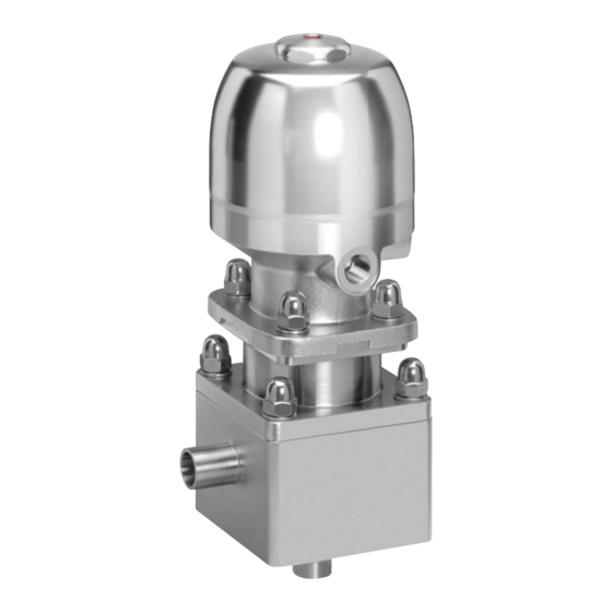
- Seite 1 Regelventil mit PD-Technologie Metall, DN 8 - 20 Control valve with PD design Metal, DN 8 - 20 ORIGINAL EINBAU- UND MONTAGEANLEITUNG INSTALLATION, OPERATING AND MAINTENANCE INSTRUCTIONS Pneumatische Ausführung Manuelle Ausführung Pneumatic design Manual design...
-
Seite 2: Inhaltsverzeichnis
Inhaltsverzeichnis 11.2 Antrieb und Zwischenstück Allgemeine Hinweise austauschen Allgemeine Sicherheitshinweise 3 11.2.1 Demontage Antrieb und Hinweise für Service- Zwischenstück und Bedienpersonal 11.2.2 Montage Antrieb und Warnhinweise Zwischenstück auf Ventilkörper Verwendete Symbole 11.3 Regelkegel austauschen Begriff sbestimmungen 11.3.1 Demontage Regelkegel Vorgesehener Einsatzbereich 11.3.2 Montage Regelkegel Technische Daten 11.4... -
Seite 3: Allgemeine Hinweise
Allgemeine Hinweise Hinweise für Service- und Bedienpersonal Beschreibungen und Die Einbau- und Montageanleitung enthält Instruktionen beziehen sich auf grundlegende Sicherheitshinweise, die bei Standardausführungen. Für Inbetriebnahme, Betrieb und Instandhaltung Sonderausführungen, die in dieser zu beachten sind. Nichtbeachtung kann zur Einbau- und Montageanleitung Folge haben: nicht beschrieben sind, gelten die Gefährdung von Personen durch... -
Seite 4: Warnhinweise
Warnhinweise Verwendete Symbole Warnhinweise sind, soweit möglich, nach Gefahr durch heiße Oberfl ächen! folgendem Schema gegliedert: SIGNALWORT Gefahr durch ätzende Stoff e! Art und Quelle der Gefahr ® Mögliche Folgen bei Nichtbeachtung. Hand: Beschreibt allgemeine Maßnahmen zur Vermeidung der Hinweise und Empfehlungen. Gefahr. -
Seite 5: Vorgesehener Einsatzbereich
Das manuell oder pneumatisch betätigte Ventil nur in explosions- gefährdeten Zonen verwenden, die auf der Konformitätserklärung (ATEX) bestätigt wurden. Das 2/2-Wege-Regelventil GEMÜ 567 ist für den Einsatz in Rohrleitungen konzipiert. Es steuert ein durchfl ießendes Medium durch einen Hand- oder Pneumatikantrieb. -
Seite 6: Technische Daten
Technische Daten Technische Daten – manuell betätigt Betriebsmedium Aggressive, neutrale, gasförmige und flüssige Medien, die die physikalischen und chemischen Eigenschaften des jeweiligen Gehäuse- und Membranwerkstoffes nicht negativ beeinflussen. Temperaturen Medientemperatur (Flüssigkeiten / Gase) Ohne Bypass -10 bis 160 °C Mit Bypass (nur Antriebsgröße 2) -10 bis 100 °C Medientemperatur (Dampf) / Sterilisationstemperatur Sitzabdichtung FPM ohne Bypass... -
Seite 7: Technische Daten - Pneumatisch Betätigt
Technische Daten – pneumatisch betätigt Betriebsmedium Aggressive, neutrale, gasförmige und flüssige Medien, die die physikalischen und chemischen Eigenschaften des jeweiligen Gehäuse- und Membranwerkstoffes nicht negativ beeinflussen. Temperaturen Medientemperatur (Flüssigkeiten / Gase) Ohne Bypass -10 bis 160 °C Mit Bypass (nur Antriebsgröße 2) -10 bis 100 °C Medientemperatur (Dampf) / Sterilisationstemperatur Sitzabdichtung FPM ohne Bypass... -
Seite 8: Kv-Werte
Kv-Werte Gleichprozentig (außer Code 59) Linear (außer Code 59) Regel- Kvs- Regel- Kvs- DN 8 DN 10 DN 15 DN 20 DN 25 DN 8 DN 10 DN 15 DN 20 DN 25 kurve Wert kurve Wert 80 l/h 80 l/h 100 l/h 100 l/h 160 l/h... -
Seite 9: Bestelldaten
Bestelldaten Bestelldaten – manuell betätigt Gehäuseform Code Ausführung Antriebsoberteil Code Eckkörper ohne Bypass Handrad A4 Edelstahl (1.4408) Eckkörper mit Bypass (nur Antriebsgröße 2) Handrad PPS Glasfaserverstärkt Anschlussart Code Antriebsfunktion Code Schweißstutzen Mit Schließ- und Hubbegrenzung Stutzen DIN Ohne Schließ- und Hubbegrenzung Stutzen EN 10357 Serie A Mit Schließ- und Hubbegrenzung, (ehemals DIN 11850 Reihe 2) / DIN 11866 Reihe A... -
Seite 10: Innenoberflächengüten Für Schmiede- Und Vollmaterialkörper
Innenoberflächengüten für Schmiede- und Vollmaterialkörper Mechanisch poliert Elektropoliert Medienberührte Hygieneklasse Hygieneklasse Innenoberflächen Code Code DIN 11866 DIN 11866 Ra ≤ 0,40 μm 1536 1537 Ra ≤ 0,25 μm 1527 1516 Mechanisch poliert Elektropoliert Medienberührte ASME BPE ASME BPE Innenoberflächen Code Code Oberflächen- Oberflächen-... - Seite 11 Bestellbeispiel 1536 ohne Bypass Nennweite Gehäuseform (Code) Anschlussart (Code) Ventilkörperwerkstoff (Code) Dichtwerkstoff (Code) Steuerfunktion (Code) Antriebsausführung (Code) Regelcharakteristik (Code) Kv-Wert (Code) Oberflächenqualität (Code) 1536 Sonderfunktion (Code) Bestellbeispiel 1536 mit Bypass Nennweite Gehäuseform (Code) Anschlussart (Code) Ventilkörperwerkstoff (Code) Dichtwerkstoff (Code) Steuerfunktion (Code) Antriebsausführung (Code) Regelcharakteristik (Code) Kv-Wert (Code)
-
Seite 12: Bestelldaten - Pneumatisch Betätigt
Bestelldaten – pneumatisch betätigt Gehäuseform Code Steuerfunktion Code Eckkörper ohne Bypass Federkraft geschlossen (NC) Eckkörper mit Bypass (nur Antriebsgröße 2) Federkraft geöffnet (NO) Beidseitig angesteuert (DA) Anschlussart Code Schweißstutzen Antriebsausführung Code Stutzen DIN Antriebsausführung 2 Stutzen EN 10357 Serie A (ehemals DIN 11850 Reihe 2) / DIN 11866 Reihe A Antriebsausführung 3 Stutzen ASME BPE / DIN 11866 Reihe C... -
Seite 13: Innenoberflächengüten Für Vollmaterialkörper
Innenoberflächengüten für Vollmaterialkörper Mechanisch poliert Elektropoliert Medienberührte Hygieneklasse Hygieneklasse Innenoberflächen Code Code DIN 11866 DIN 11866 Ra ≤ 0,40 μm 1536 1537 Ra ≤ 0,25 μm 1527 1516 Mechanisch poliert Elektropoliert Medienberührte ASME BPE ASME BPE Innenoberflächen Code Code Oberflächen- Oberflächen- nach ASME BPE 2016 bezeichnung... - Seite 14 Bestellbeispiel 1536 ohne Bypass Nennweite Gehäuseform (Code) Anschlussart (Code) Ventilkörperwerkstoff (Code) Dichtwerkstoff (Code) Steuerfunktion (Code) Antriebsausführung (Code) Regelcharakteristik (Code) Kv-Wert (Code) Oberflächenqualität (Code) 1536 Sonderfunktion (Code) Bestellbeispiel 1536 mit Bypass Nennweite Gehäuseform (Code) Anschlussart (Code) Ventilkörperwerkstoff (Code) Dichtwerkstoff (Code) Steuerfunktion (Code) Antriebsausführung (Code) Regelcharakteristik (Code) Kv-Wert (Code)
-
Seite 15: Herstellerangaben
Herstellerangaben Funktionsbeschreibung Das 2/2-Wege-Regelventil GEMÜ 567 Transport BioStar control ist für den Einsatz in sterilen Anwendungsbereichen konzipiert. Je Ventil nur auf geeignetem Lademittel nach Ausführung sind Durchflussmengen transportieren, nicht stürzen, vorsichtig von 80 l/h bis 12.500 l/h möglich. Das handhaben. -
Seite 16: Geräteaufbau
Geräteaufbau PD-Dichtsystem Abdichtung Code 4 Pneumatische Ausführung Steuermedium- anschluss 4 Steuermedium- anschluss 2 Aufbau PD-Dichtsystem GEMÜ 567 ohne Bypass Medienberührende Werkstoffe Geräteaufbau pneumatische Ausführung PTFE Konusmembrane (Antriebsabdichtung) FPM - O-Ring (Sitzabdichtung) Ventilkörper Edelstahl (1.4435) Regelkegel Zwischenstück Edelstahl (1.4435) Stützring Antrieb Manuelle Ausführung... -
Seite 17: Pd-Dichtsystem Abdichtung Code
10.1 Montage des Ventils WARNUNG Unter Druck stehende Armaturen! ® Gefahr von schwersten Verletzungen oder Tod! Nur an druckloser Anlage arbeiten. Aufbau PD-Dichtsystem GEMÜ 567 ohne Bypass WARNUNG Aggressive Chemikalien! ® Verätzungen! Montage nur mit geeigneter Schutzausrüstung. VORSICHT Heiße Anlagenteile! ®... - Seite 18 Installationsort: VORSICHT Ventil äußerlich nicht stark beanspruchen. Installationsort so wählen, dass Ventil nicht als Steighilfe genutzt werden kann. Rohrleitung so legen, dass Schub- und Biegungskräfte, sowie Vibrationen Montage: und Spannungen vom Ventilkörper ferngehalten werden. 1. Eignung des Ventils für jeweiligen Ventil nur zwischen zueinander Einsatzfall sicherstellen.
-
Seite 19: Steuerfunktionen (Pneumatische Ausführung)
Montage bei Clampanschluss: 1. Entsprechende Dichtung zwischen Ventilkörper und Rohranschluss Steuermedium- einlegen. anschluss 4 Die Dichtung ist nicht im Liefer- umfang enthalten. Steuermedium- 2. Ventilkörper mit Dichtung und anschluss 2 Rohranschluss mit Klammer verbinden. Die Klammer ist nicht im Liefer- umfang enthalten. -
Seite 20: Steuermedium Anschließen
Montage / Demontage 10.3 Steuermedium anschließen von Ersatzteilen Wichtig: Steuermediumleitung spannungs- 11.1 Antrieb austauschen und knickfrei montieren! Je nach Anwendung geeignetes Anschlussstück verwenden. Gewinde der Steuermediumanschlüsse: G1/4 Z18a Z18a Steuerfunktion Anschluss Z17a Z17a Federkraft 2: Steuermedium (Öffnen) geschlossen (NC) Z16a Z16a Federkraft 4: Steuermedium (Schließen) -
Seite 21: 11.1.2 Montage Antrieb Auf
11.1.2 Montage Antrieb auf 11.2.2 Montage Antrieb und Zwischenstück Zwischenstück auf Ventilkörper 1. Antrieb A in Off en-Position bringen. 1. Antrieb A und Zwischenstück Z11 auf 2. Antrieb A auf Zwischenstück Z11 Ventilkörper Z1 aufsetzen. aufsetzen. 2. Unterlegscheiben Z17b und 3. -
Seite 22: 11.3.2 Montage Regelkegel
11.3.2 Montage Regelkegel Sollten sich bei der Demontage des Regelkegels Z3 die Membrane Z2, die Spannmutter Z5 und die Tellerfedern Z9 lösen, müssen diese vor der Montage des Regelkegels Z3 wieder lagerichtig positioniert werden (siehe auch Kapitel 19 "Schnittbilder und Ersatzteile"). 6. - Seite 23 11.4 Konusmembrane aus- 5. Stützring Z20 handfest an Ventilspindel Z6 schrauben. tauschen, Abdichtung Code 4 Bei Bedarf das Gewinde der 11.4.1 Demontage Konusmembrane Ventilspindel Z6 mit geeigneter 1. Stützring Z20 und Regelkegel Z3 Schraubensicherung (z. B. demontieren (siehe Kapitel 11.3.1 WEICONLOCK AN 301-65) "Demontage Regelkegel").
-
Seite 24: Konusmembrane Austauschen
11.5 Konusmembrane aus- 11.5.2 Montage Konusmembrane tauschen, Abdichtung Code 5 1. Konusmembrane Z2 handfest an Ventilspindel Z6 schrauben. Z18b Z17b Z16b 2. Zwischenstück Z11 auf Ventilkörper Z1 aufsetzen. 3. Unterlegscheiben Z17b und Hutmuttern Z18b handfest auf Stiftschrauben Z16b legen. 4. Hutmuttern Z18b über Kreuz festziehen 11.5.1 Demontage Konusmembrane (Anzugsdrehmoment: 16-20 Nm). -
Seite 25: 11.7 Demontage Membrane
11.7 Demontage Membrane Wichtig: Ist die Membrane nicht weit Wichtig: genug in das Verbindungsstück Vor Demontage der Membrane eingeschraubt, wirkt die bitte Antrieb demontieren, siehe Schließkraft direkt auf den "Demontage Ventil (Antrieb vom Membranpin und nicht über Körper lösen)". das Druckstück. Das führt zu 1. -
Seite 26: 11.9 Montage Antrieb Auf Ventilkörper
Inbetriebnahme 2. Membrane mit angeformtem Befestigungszapfen schräg an WARNUNG Druckstückaussparung ansetzen. Wichtig: Aggressive Chemikalien! Keine Fette oder Schmierstoff e ® Verätzungen! verwenden! Vor Inbetriebnahme Dichtheit der Medienanschlüsse 3. Von Hand hineindrehen / hineindrücken. prüfen! 4. Lasche mit Hersteller- und Dichtheitsprüfung nur mit Werkstoff... -
Seite 27: Demontage
Rücksendung VORSICHT Ventil reinigen. Wartungs- und Rücksendeerklärung bei GEMÜ Instandhaltungstätigkeiten nur durch anfordern. geschultes Fachpersonal. Rücksendung nur mit vollständig Für Schäden welche durch ausgefüllter Rücksendeerklärung. unsachgemäße Handhabung oder Ansonsten erfolgt keine Fremdeinwirkung entstehen, übernimmt Gutschrift bzw. keine GEMÜ keinerlei Haftung. Erledigung der Reparatur Nehmen Sie im Zweifelsfall vor sondern eine kostenpflichtige Entsorgung. -
Seite 28: 18 Fehlersuche / Störungsbehebung
Fehlersuche / Störungsbehebung Fehler Möglicher Grund Fehlerbehebung Steuermedium entweicht Steuermedium auf Verschmutzungen untersuchen, Antrieb defekt aus Leckagebohrungen* ggf. Ventil zur Reparatur an GEMÜ senden Betriebsmedium entweicht Konusmembrane auf Beschädigungen prüfen, ggf. Konusmembrane* defekt aus Leckagebohrungen* Konusmembrane tauschen Steuerdruck zu niedrig Steuerdruck gemäß... -
Seite 29: 19 Schnittbilder Und Ersatzteile 17 19.1 Manuelle Ausführung Abdichtung 17 Code
19.1 Manuelle Ausführung Abdichtung Code 4 Montagewerkzeug Z18a Leckagebohrung Z17a Z18b Leckagebohrung Z17b Pos. Benennung Bestellbezeichnung Pos. Benennung Bestellbezeichnung Konusmembrane Ventilkörper 567 SVS... O-Ring Spannmutter Konusmembrane Ventilspindel O-Ring 567 SVM... Tellerfedern Montagewerkzeug Zwischenstück Konusmembrane Unterlegscheibe Regelkegel Hutmutter 567 SRK... O-Ring... -
Seite 30: Manuelle Ausführung Abdichtung Code 5
19.2 Manuelle Ausführung Abdichtung Code 5 Z18a Leckagebohrung Z17a Z18b Leckagebohrung Z17b Pos. Benennung Bestellbezeichnung Pos. Benennung Bestellbezeichnung Konusmembrane Ventilkörper 567 SVS... O-Ring Spannmutter Konusmembrane Ventilspindel O-Ring 567 SVM... Tellerfedern Montagewerkzeug Zwischenstück Konusmembrane Unterlegscheibe Regelkegel Hutmutter 567 SRK... O-Ring Antrieb Montagewerkzeug Weitere Ersatzteile auf Anfrage. -
Seite 31: Pneumatische Ausführung Abdichtung Code
19.3 Pneumatische Ausführung Abdichtung Code 4 Montagewerkzeug Leckagebohrung Z18a Z17a Z18b Leckagebohrung Z17b Pos. Benennung Bestellbezeichnung Pos. Benennung Bestellbezeichnung Konusmembrane Ventilkörper 567 SVS... O-Ring Spannmutter Konusmembrane Ventilspindel O-Ring 567 SVM... Tellerfedern Montagewerkzeug Zwischenstück Konusmembrane Unterlegscheibe Regelkegel Hutmutter 567 SRK... O-Ring... -
Seite 32: Pneumatische Ausführung
19.4 Pneumatische Ausführung Abdichtung Code 5 Leckagebohrung Z18a Z17a Z18b Leckagebohrung Z17b Pos. Benennung Bestellbezeichnung Pos. Benennung Bestellbezeichnung Konusmembrane Ventilkörper 567 SVS... O-Ring Spannmutter Konusmembrane Ventilspindel O-Ring 567 SVM... Tellerfedern Montagewerkzeug Zwischenstück Konusmembrane Unterlegscheibe Regelkegel Hutmutter 567 SRK... O-Ring Antrieb Montagewerkzeug Weitere Ersatzteile auf Anfrage. - Seite 33 31.03.2016 Projektnummer: SV-Pneum-2015-11 Handelsbezeichnung: Typ 567 Es wird erklärt, dass die folgenden grundlegenden Anforderungen der Maschinenrichtlinie 2006/42/EG erfüllt sind: 1.1.3.; 1.1.5.; 1.1.7.; 1.2.1.; 1.3.; 1.3.2.; 1.3.4.; 1.3.7.; 1.3.9.; 1.5.3.; 1.5.5.; 1.5.6.; 1.5.7.; 1.5.8.; 1.5.9.; 1.6.5.; 2.1.1.; 3.2.1.; 3.2.2.; 3.3.2.; 3.6.3.1.; 4.1.2.1.; 4.1.2.3.; 4.1.2.4.; 4.1.2.5.; 4.1.2.6. a); 4.1.2.6. c);...
-
Seite 34: Herstellererklärung
Max. zulässiger Betriebsdruck PS: 10 bar Max. Nennweite: DN 20 Mediumeigenschaft nach Artikel 9: Gruppe 1 – gefährlich Benennung der Armaturen - Typenbezeichnung: Regelventil GEMÜ 567 Einstufung der Amaturen: Nach Artikel 4, Absatz 3 gute Ingenieurpraxis DN ≤ 25 Zusätzliche Angaben: Die Produkte werden entwickelt und produziert nach GEMÜ... - Seite 68 GEMÜ Gebr. Müller Apparatebau GmbH & Co. KG · Fritz-Müller-Str. 6-8 · D-74653 Ingelfi ngen-Criesbach Telefon +49(0)7940/123-0 · Telefax +49(0)7940/123-192 · info@gemue.de · www.gemu-group.com...