Inhaltsverzeichnis
Werbung
Verfügbare Sprachen
Verfügbare Sprachen
Quicklinks
Visit www.carrier.com
Installation and Start-Up Instructions
NOTE: Read the entire instruction manual before starting the
installation.
This symbol → indicates a change since the last issue.
SAFETY CONSIDERATIONS
Improper installation, adjustment, alteration, service, maintenance,
or use can cause explosion, fire, electrical shock, or other
conditions which may cause death, personal injury, or property
damage. Consult a qualified installer, service agency, or your
distributor or branch for information or assistance. The qualified
installer or agency must use factory-authorized kits or accessories
when modifying this product. Refer to the individual instructions
packaged with the kits or accessories when installing.
Follow all safety codes. Wear safety glasses, protective clothing,
and work gloves. Use quenching cloth for brazing operations.
Have fire extinguisher available. Read these instructions thor-
oughly and follow all warnings or cautions included in literature
and attached to the unit. Consult local building codes and National
Electrical Code (NEC) for special requirements.
Recognize safety information. This is the safety-alert symbol
When you see this symbol on the unit and in instructions or
manuals, be alert to the potential for personal injury.
Understand the signal words DANGER, WARNING, and CAU-
TION. These words are used with the safety-alert symbol. DAN-
GER identifies the most serious hazards which will result in severe
personal injury or death. WARNING signifies hazards which
could result in personal injury or death. CAUTION is used to
identify unsafe practices which would result in minor personal
injury or product and property damage. NOTE is used to highlight
suggestions which will result in enhanced installation, reliability,
or operation.
Before installing, modifying, or servicing system, main elec-
trical disconnect switch must be in the OFF position. There
may be more than 1 disconnect switch. Lock out and tag
switch with a suitable warning label. Electrical shock can
cause personal injury or death.
Puron® (R-410A) systems operate at higher pressures than
standard R-22 systems. Be certain that service equipment is
rated for Puron® to prevent unit damage. Some R-22 service
equipment may not be acceptable. Check with your distribu-
tor.
INSTALLATION RECOMMENDATIONS
NOTE: In some cases noise in the living area has been traced to
gas pulsations from improper installation of equipment.
1. Locate unit away from windows, patios, decks, etc. where unit
operation sound may disturb customer.
2. Ensure that vapor and liquid tube diameters are appropriate to
capacity of unit.
Manufacturer reserves the right to discontinue, or change at any time, specifications or designs without notice and without incurring obligations.
Book 1 4
PC 101
Catalog No. 003-80011
Tab 5a 5a
.
3. Run refrigerant tubes as directly as possible by avoiding
unnecessary turns and bends.
4. Leave some slack between structure and unit to absorb
vibration.
5. When passing refrigerant tubes through the wall, seal opening
with RTV or other pliable silicon-based caulk. (See Fig. 2.)
6. Avoid direct tubing contact with water pipes, duct work, floor
joists, wall studs, floors, and walls.
7. Do not suspend refrigerant tubing from joists and studs with a
rigid wire or strap which comes in direct contact with tubing.
(See Fig. 2.)
8. Ensure that tubing insulation is pliable and completely sur-
rounds vapor tube.
9. When necessary, use hanger straps which are 1 in. wide and
conform to shape of tubing insulation. (See Fig. 2.)
10. Isolate hanger straps from insulation by using metal sleeves
bent to conform to shape of insulation.
When outdoor unit is connected to factory-approved indoor unit,
outdoor unit contains system refrigerant charge for operation with
indoor unit of same size when connected by 7.6 m of field-supplied
or factory accessory tubing. Add (or subtract) 56 g of 9.5 mm
liquid line for lengths greater (or less) than 7.6 m. For proper unit
operation, check refrigerant charge using charging information
located on control box cover and/or in the Check Charge section of
this instruction.
Printed in U.S.A.
Form 38EYX-C1SI
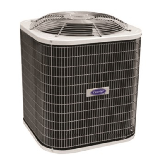
38EYX—50 HZ
Heat Pump with
Puron® Refrigerant
Fig. 1—Model 38EYX
Pg 1
11-03
A03171
Replaces: New
Werbung
Inhaltsverzeichnis

Verwandte Anleitungen für Carrier 38 EYX-50 HZ


Inhaltszusammenfassung für Carrier 38 EYX-50 HZ
- Seite 1 38EYX—50 HZ Heat Pump with Puron® Refrigerant Visit www.carrier.com Installation and Start-Up Instructions NOTE: Read the entire instruction manual before starting the installation. This symbol → indicates a change since the last issue. SAFETY CONSIDERATIONS Improper installation, adjustment, alteration, service, maintenance,...
-
Seite 2: Installation
IMPORTANT: Maximum liquid-line size is 3/8-in. (9.5 mm) O.D. for all residential applications including long line. IMPORTANT: Always install the factory-supplied Puron® heat pump (bi-flow) liquid-line filter drier. If replacing the filter drier, refer to Product Data Digest for appropriate part number. Obtain replacement filter driers from your distributor or branch. - Seite 3 Step 5—Elevate Unit Step 9—Making Piping Connections Accumulation of water and ice in base pan may cause Relieve pressure and recover all refrigerant before system equipment damage. repair or final unit disposal to avoid personal injury or death. Use all service ports and open all flow-control devices, Elevate unit per local climate and code requirements to provide including solenoid valves.
- Seite 4 Table 1—Refrigerant Connections and Recommended Liquid Line and Vapor Tube Diameters-In. (mm) TUBE DIAMETER CONNECTION DIAMETER TUBE DIAMETER UNIT (ALTERNATE) SIZE Liquid Vapor Liquid Vapor Vapor 3/8 (9.5) 5/8 (15.9) 3/8 (9.5) 5/8 (15.9) 3/4(19.1) 3/8 (9.5) 3/4 (19.1) 3/8 (9.5) 3/4 (19.1) 5/8, 7/8 (15.9, 22.2) 3/8 (9.5)
- Seite 5 Table 2—Accessory Usage REQUIRED FOR LOW-AMBIENT REQUIRED FOR LONG-LINE ACCESSORY APPLICATIONS APPLICATIONS* (BELOW 55°F/13°C) (OVER 50 FT/15 M) Crankcase Heater Evaporator Freeze Thermostat Compressor Start Assist—Capacitor and Relay Puron® Low-Ambient Pressure Switch Wind Baffle See Low-Ambient Instructions Support Feet Recommended Hard Shutoff TXV See Long-Line Liquid-Line Solenoid Valve for Heating...
- Seite 6 TYPICAL HEAT HP THERMOSTAT FAN COIL PUMP 24 VAC HOT 24 VAC COM HEAT STAGE 2 COOL/HEAT STAGE 1 INDOOR FAN RVS COOLING EMERGENCY IF AVAILABLE HEAT A02325 Fig. 10—Generic Wiring Diagram (See Thermostat Installation Instructions for wiring specific unit combinations) The unit cabinet must have an uninterrupted or unbroken ground to minimize personal injury if an electrical fault should occur.
-
Seite 7: Sequence Of Operation
A crankcase heater is required in long-line applications (tubing are equipped with a phase monitor to detect if the incoming power greater than 50 ft (15 m) horizontal and/or elevation greater than is correctly phased for compressor operation. (See Fig. 11 and 20 ft (6 m) between indoor and outdoor units). - Seite 8 CESO130076–00 Speedup Quiet Defrost interval Pins Shift DIP switches A99442 Fig. 12—Defrost Control short defrost cycle will be observed (actual length is dependent The following procedure is valid when indoor airflow is within ± upon the selected Quiet Shift position). When Quiet Shift switch is 21 percent of its rated CFM.
-
Seite 9: Care And Maintenance
Table 4—Superheat Charging Table (SI) OUTDOOR EVAPORATOR ENTERING AIR TEMPERATURE (°C WB) TEMP (°C) 11.1 11.9 12.8 14.4 16.1 17.8 19.4 20.6 22.2 23.3 25.0 10.0 10.8 11.7 13.3 15.0 16.7 18.3 20.0 21.1 22.2 23.9 – 10.6 11.7 13.3 15.0 16.7 18.3... - Seite 10 • Do not use capillary tube coils. • Observe all warnings, cautions, and bold text. Copyright 2004 CARRIER Corp. • 7310 W. Morris St. • Indianapolis, IN 46231 38eyxc1si Manufacturer reserves the right to discontinue, or change at any time, specifications or designs without notice and without incurring obligations.
-
Seite 11: Instalación
38EYX-50HZ Bomba de calor con refrigerante Puron ® Visite la web www.carrier.com Instrucciones de instalación y de puesta en marcha NOTA: Leer el manual de instrucciones en su totalidad antes de poner en Vea la Figura 1 en la versión en inglés de este marcha la instalación. - Seite 12 Localizar en el panel angular de la unidad la placa de identificación Fase 7 - Comprobar el termostato de deshelado de la misma que contiene las informaciones necesarias para instalar Comprobar el termostato de deshelado para asegurarse de que esté correctamente la unidad.
- Seite 13 Las unidades exteriores pueden ser conectadas a la sección interior utili- COMPROBACIÓN DE PÉRDIDAS zando los tubos accesorios ó los tubos de refrigerante del comercio de Efectuar una prueba de estanqueidad en todas las juntas de las tube- tamaño adecuado. En los tubos de más de 15 m. de largo, podría produ- rías interiores, exteriores y de refrigerante.
- Seite 14 Utilizar el cable aislado (mínimo 35°C) de color escala AWG n° 18. ATENCIÓN Si el termostato está situado a más de 100 pies (30 m.) de la unidad, Para evitar riesgos de lesiones o la muerte, no conectar la uni- según resulta de los cables de tensión, utilizar el cable de color esca- dad al suministro eléctrico si la tapa del tablero de bornes del la AWG n°...
- Seite 15 Seguir las Instrucciones para poner en marcha el sistema. Si la temperatura siguiera disminuyendo, el circuito R-W2 se conectaría a través del termostato ambiente. El circuito R-W2 pone bajo tensión el 1. Abrir completamente las válvulas de servicio del líquido y del agua. calentador adicional (si se utiliza).
-
Seite 16: Carga De La Unidad
dejando que la escarcha se acumule sobre la batería exterior. carga y pesar la carga correcta de refrigerante. 4. Después de pocos minutos en modo de calefacción, la temperatu- NOTA: Cuando es necesario añadir refrigerante durante la tempo- ra de la línea de líquido tiene que bajar por debajo del punto de cie- rada de calefacción, hay que pesar la carga conformemente a lo indi- rre del termostato de deshelado (aproximadamente 30°F/-1°C). - Seite 17 · Reemplazar siempre el deshidratador del filtro después de la apertura del sistema para las operaciones de mantenimiento. · No exponer el Puron® al aire. · No utilizar bobinas para tubos capilares. · Respetar todas las advertencias y leer los textos en negrita. Vea la Tabla 4 en la versión en inglés de este documento Vea la Tabla 5 en la versión en inglés de este...
- Seite 18 38 EYX-50 HZ Wärmepumpe mit Kältemittel Puron® Installation und Inbetriebnahme Hinweis: Betriebsanweisungen vor der Installation durchlesen. Flüssigkeitsleitungen dem Leistungsvermögen des Geräts ange- passt sind. Dieses Zeichen zeigt eine Änderung gegenüber der vorigen 3. Leitungen des Kältemittels mit möglichst wenigen Kurven oder Biegungen installieren.
-
Seite 19: Verpackung Entfernen
Wartungsanweisungen Split-System Klimageräte für Wohnungen und der Wärmepumpen mit Kältemittel Puron®.. Schritt 4 - Temperatur des Betriebsraums Die minimale Außentemperatur für den Betrieb "Kühlung" ohne Schritt 1 - Überprüfung der Bauelemente und des Zubehörteile ist 13°C, die maximale Außentemperatur für den Installationsorts Betrieb "Kühlung"... - Seite 20 ne Durchmesser für Flüssigkeits- und Gasrohrleitungen, ange- AUCHTUNG geben in Zoll (mm) Um schwere Verletzungen oder Tod zu vermeiden, ist der Druck auszuschalten und das gesamte Kältemittel zu fangen, bevor das System zu reparieren oder das Gerät endgültig zu entsorgen. Alle Öffnungen dazu...
- Seite 21 (Nationale Ordnung für das elektrische Material). Der Trennschalter Bitte schauen Sie sich Abb. 5 der englischen Version soll sichtbar und vom Gerät leicht zugänglich sein, wie im NEC dieses Dokuments an. Kapitel 440-40 oder in der lokalen Norm angegeben ist. INSTALLATION DER ERDUNGS- UND VERSORGUNGSKA- Bitte schauen Sie sich Abb.
- Seite 22 Der Gehäuse-Erhitzer ist notwendig bei der Installation von langen HINWEIS: Die Schalttafel zur Abtauung ist mit einem Schutztimer Leitungen (Rohrlänge mehr als 50 Fuß (15 m) horizontal und/oder (Schaltdauer: 5 Minuten) im Fall von Stromausfall ausgestattet. mit einer Höhe von mehr als 20 Fuß (6 m) zwischen Innen- und Der Transformator ist durch den Versorgungsstrom zum Außen- und Außengerät.
-
Seite 23: Verfahren Zur Kontrolle Während Heizzyklus
Die Abtau-Kontrolle ist eine Zeit-/Temperaturkontrolle mit einstell- kontrollieren. barer Zeit (Mikroschalter 1 und 2 auf der Tafel) zwischen den 2. Ansaugdruck messen, indem ein Messgerät an der Öffnung des Abtauzyklen von 30, 60, 90 oder 120 Minuten (bauseitige Ansaugventils angeschlossen wird. Einstellung 90 Minuten). -
Seite 24: Aufbewahrung Und Wartung
Systemfunktion und periodische, im Handbuch beschriebene Wartungsarbeiten erläutern. 4. Installationskarte der Verkäufer ausfüllen und im Kundenarchiv auf- bewahren. AUFBEWAHRUNG UND WARTUNG eine hohe Leistung gewährleisten Bauelementebeschädigungen auf ein Minimum zu reduzieren, ist eine periodische Wartung durchzuführen. Die Frequenz der Wartungsarbeiten kann je nach den geografischen Zonen unterschiedlch sein (z.B., wenn das Gerät in einer Küstenzone installiert ist). -
Seite 25: Installatie En Inbedrijfstelling
38 EYX-50 HZ Warmtepomp met koelmiddel Puron® Installatie en Inbedrijfstelling MONTAGE-INSTRUCTIES Nota: De gebruiksaanwijzingen aandachtig lezen alvorens met de ins- tallatie te beginnen. NOTA: In enkele gevallen werd geruis wegens de gas pulsaties Dit symbool betekent een wijziging ten opzichte van de vooraf- geregistreerd, veroorzaakt door de verkeerde installatie van de gaande uitvoering. - Seite 26 BELANGRIJK: Volgens de specificaties betrekkelijk de installatie Indien de unit op het dak gemonteerd wordt, deze minstens 15 cm van het apparaat in nieuwbouwwoningen moeten de buitenunit, de boven de dakoppervlakte plaatsen. binnenunit, de koelmiddelleidingen, de doseerinrichting en de filter- droger uitsluitend degene zijn, die in de brochure aangegeven zijn.
- Seite 27 LET OP Cf. tabel 1 in de Engelstalige versie van dit docu- ment. Om ernstige verwondingen of de dood van de technicus te voorko- men, moet de druk geannuleerd en het koelmiddel volledig opge- KOELMIDDELLEIDINGEN EN FILTERDROGER vangen worden alvorens het systeem te repareren of de unit defini- tief te verwijderen.
- Seite 28 INSTALLATIE VAN DE AARDKABELS EN VAN DE VOE- Cf. tabel 2 in de Engelstalige versie van dit docu- DINGSKABELS ment. Het paneel voor toegang tot de bedrading van de unit verwijderen. Beschermingsbuizen in de vooraf geboorde gaten in het onderste gedeelte van het schakelbord installeren.
- Seite 29 De toepassing van de carterverhitter is noodzakelijk bij de installa- WERKINGSVOLGORDE tie van lange lijnen (buizen met een lengte van meer dan 50 voeten (50 m) horizontal en/of met een hoogte van meer dan 20 voeten (6 NOTA: Het bedieningspaneel voor ontdooiing is uitgerust met een vei- tussen binnenunit buitenunit).
-
Seite 30: Verzorging En Onderhoud
Ontdooiing 10 m - 7,6 m = 2,4 m X 56 g/m = 134,4 g aanvullende lading. Het commando voor ontdooiing is een tijd/temperatuur controle met een kiesbare tijdperiode (microschakelaar 1 en 2 op het paneel) tussen de De volgende procedure is geldig, wanneer de binnenluchtstroom ± ontdooiingcycli van 30, 60, 90 of 120 minuten (instelling van 90 minu- 21% van de nominale waarde CFM (kubieke meters per minuut) is. - Seite 31 REFERENTIEGIDS Puron® (R-410A) · Het koelmiddel Puron® werkt bij een druk, die 50-70% hoger is ten opzichte van R-22. Controleren dat de service uitrusting en de reserve- onderdelen geschikt zijn voor de werking met Puron®.. · De flessen van het koelmiddel Puron® zijn roze. ·...
- Seite 32 38 EYX-50 HZ Pompe à chaleur et flui- de réfrigérant Puron® Instructions d'installation et de démarrage Note: Lire attentivement la Notice d'Utilisation avant l'installation. CONSIGNES D'INSTALLATION NOTE: En quelques occasions, des bruits causés par les pulsations Le symbole indique une modification par rapport à la version des dispositifs du gaz dues à...
- Seite 33 le déshydrateur du filtre à utiliser sont ceux indiqués dans la docu- Phase 4 - Température ambiante de fonctionnement mentation. En cas de modifications pour des applications spéciales et de la conversion du système R-22, consulter la Notice La température minimum extérieure de fonctionnement en mode d'Utilisation et d'Entretien des Climatiseurs Split-System et des refroidissement et sans accessoires supplémentaires est de 13°C, et Pompes à...
- Seite 34 Veuillez vous reporter au Tableau 1 de la version ATTENTION anglais de ce document Afin d'éviter des lésions ou la mort de l'opérateur, dégager la pres- sion et vidanger tout le fluide réfrigérant avant de réparer le systè- TUYAUX DU FLUIDE RÉFRIGÉRANT ET DÉSHYDRATEUR me ou d'éliminer définitivement l'unité.
- Seite 35 NOTE: Installer un disjoncteur de circuit en dérivation dont les Veuillez vous reporter à la Fig. 5 de la version anglai- dimensions sont conformes au NEC (code national du matériel élec- se de ce document. trique) pour contrôler le courant de démarrage. Positionner le dis- joncteur en position visible et accessible ainsi comme il est indiqué...
- Seite 36 SÉQUENCE DE FONCTIONNEMENT Phase 11 - Réchauffeur du carter du compresseur Si l'unité est équipée d'un réchauffeur du carter, alimenter le NOTE: Le tableau des commandes de dégivrage est équipé d'un tempo- réchauffeur au moins 24 heures avant le démarrage de l'unité. Pour risateur de protection qui s'active pendant 5 minutes et qui peut être acti- n'alimenter que le réchauffeur, programmer le thermostat sur OFF et vé...
-
Seite 37: Entretien
(micro-interrupteur 1 et 2 du panneau) entre les cycles de dégivrage Cette procédure s'applique lorsque l'écoulement d'air intérieur est de 30, 60, 90 ou 120 minutes (programmation du fabricant 90 minu- égal à ± 21% de la valeur nominale CFM (mètres cubes par minu- tes). - Seite 38 pannes de l'équipement, effectuer périodiquement toutes les opéra- tions d'entretien. La fréquence de l'entretien varie suivant les aires géographiques (par exemple si l'unité est installée dans une zone maritime). GUIDE DE RÉFÉRENCE DU Puron® (R-410A) · Le fluide réfrigérant Puron® fonctionne à des pressions supérieu- res de 50-70% à...
-
Seite 39: Installazione Ed Avviamento
38 EYX-50 HZ Pompa di calore con refrigerante Puron® Installazione ed Avviamento Nota: Leggere completamente il manuale di istruzioni prima di inizia- ISTRUZIONI DI INSTALLAZIONE NOTA: In alcuni casi si sono rilevati dei rumori dovuti alle pulsazio- re l'installazione. ni dei dispositivi del gas causati dall'errata installazione dell'attrezza- tura. - Seite 40 nità interna, i tubi del refrigerante, il misuratore e l'essiccatore del fil- frescamento senza accessori aggiuntivi è di 13°C, mentre la tempera- tro devono essere esclusivamente quelli indicati nel materiale illustra- tura massima esterna per il funzionamento in modalità raffrescamento tivo.
- Seite 41 ATTENZIONE Fare riferimento alla Tabella 1 nella versione inglese di questo documento Al fine di evitare ferimenti gravi o la morte dell'operatore, annu- llare la pressione e recuperare tutto il refrigerante prima di ripara- TUBI DEL REFRIGERANTE ED ESSICCATORE DEL FILTRO re il sistema o di smaltire definitivamente l'unità.
- Seite 42 conformi al NEC (codice nazionale per il materiale elettrico) per con- Fare riferimento alla Fig. 5 della versione inglese di trollare la corrente di avviamento. Collocare il sezionatore in maniera questo documento. che risulti visibile e facilmente accessibile dall'unità, così come indica- to nel Capitolo 440-40 del NEC o nella normativa locale.
-
Seite 43: Sequenza Di Funzionamento
SEQUENZA DI FUNZIONAMENTO L'applicazione del riscaldatore del carter è necessaria nell'installa- zione di linee estese (tubi di lunghezza superiore a 50 piedi (15 m) NOTA: Il quadro dei comandi di sbrinamento è dotato di un timer di in orizzontale e/o con altezza superiore a 20 piedi (6 m) fra l'unità protezione che si attiva per 5 minuti che può... -
Seite 44: Conservazione E Manutenzione
(microinterruttore 1 e 2 sul pannello) fra i cicli di sbrinamento di 30, linea di 10 m: 60, 90 o 120 minuti (impostazione del fabbricante 90 minuti). 10 m - 7,6 m = 2,4 m X 56 g/m = 134,4 g di carica aggiuntiva. Per dare inizio ad un ciclo forzato di sbrinamento, vi sono due pos- La seguente procedura è... - Seite 45 trezzatura, eseguire la manutenzione periodica dell'attrezzatura. La frequenza della manutenzione può variare a seconda delle aree geografiche (ad esempio se l'unità è installata in una zona costiera). GUIDA RAPIDA DI RIFERIMENTO DEL Puron® (R-410A) · Il refrigerante Puron® funziona a pressioni superiori del 50-70% rispetto al R-22.
- Seite 46 38EYX-50Hz Αντλία θερµότητας µε ψυκτικό µέσον Puron® Οδηγίες για την εγκατάσταση και την θέση σε λειτουργία ΣΗΜΕΙΩΣΗ: Πριν ξεκινήσετε την εγκατάσταση, διαβάστε Q ΠΡΟΣΟΧΗ προσεκτικά το εγχειρίδιο αυτό. Το σύστηµα µε ψυκτικό µέσον Puron® (R-410A) Το σύµβολο αυτό → επισηµαίνει µια αλλαγή σε σχέση µε λειτουργεί...
- Seite 47 µέγεθος του υπόβαθρου και για να εντοπίσετε τη θέση Όταν η εξωτερική µονάδα είναι συνδεδεµένη µε µια των οπών. εσωτερική µονάδα εγκεκριµένη από το εργοστάσιο, η εξωτερική µονάδα περιέχει σύστηµα φόρτισης του Στις συσκευές οροφής, τοποθετήστε τη µονάδα πάνω σε ψυκτικού...
- Seite 48 Φάση 6 – Έλεγχος Εσωτερικής ∆ιάταξης Εκτόνωσης Q ΠΡΟΣΟΧΗ Q ΠΡΟΣΟΧΗ Μην αφήνετε το σύστηµα ανοικτό στην αέριοφαιρα Ελέγξτε το έµβολο του εσωτερικού στοιχείου για να δείτε περισσότερο από το µέγιστο απαιτούµενο για την αν ταιριάζει µε το απαιτούµενο έµβολο που αναγράφεται εγκατάσταση.
- Seite 49 4. Αφαιρέστε από τη σακούλα τη ροδέλα από τεφλόν και Μέθοδος βαθέως κενού περάστε την στο ανοικτό άκρο της βαλβίδας συντήρησης Η µέθοδος βαθέως κενού απαιτεί µια αντλία κενού 500 του υγρού (βλέπε Εικ. 5). microns και ένα κενόµετρο που µπορεί να µετρήσει αυτό το...
- Seite 50 κανονισµό της ∆ΕΗ. Βεβαιωθείτε επίσης πως η παροχή πληροφορίες συµβουλευθείτε τον κανονισµό IEC 60355- ισχύος στη συσκευή είναι συµβατή µε τα τεχνικά 1, Μέρος 25. χαρακτηριστικά που αναγράφονται στην πινακίδα της. Επικοινωνήστε µε τη ∆ΕΗ αν η τάση είναι ασύµβατη. Χρησιµοποιήστε...
- Seite 51 Q ΠΡΟΣΟΧΗ Προκειµένου να µην τραυµατιστείτε, όταν χρησιµοποιείτε το ψυκτικό µέσο πρέπει να φοράτε τα κατάλληλα Στα τριφασικά µοντέλα που είναι εφοδιασµένα µε προστατευτικά ρούχα, γυαλιά και γάντια. σπειροειδείς συµπιεστές (scroll), οι µονάδες έχουν µια διάταξη επιτήρησης της φάσης που ελέγχει αν το εισερχόµενο...
- Seite 52 ο συµπιεστής θα σταµατήσει για 30 δευτερόλεπτα και ο τον αγωγό του κινητήρα του ανεµιστήρα, αφού ξεκινήσετε ανεµιστήρας θα σταµατήσει για 40 δευτερόλεπτα, πριν εξαναγκαστικά τον κύκλο απόψυξης. από την επανεκκίνηση της λειτουργίας θέρµανσης. Φάση 14 – Έλεγχος φόρτισης Απόψυξη ΦΟΡΤΙΣΗ...
- Seite 53 10. Όταν προσθέτετε ψυκτικό µέσο, φορτίστε το σε υγρή µορφή στο στόµιο συντήρησης της αναρρόφησης, ΣΥΝΤΟΜΟΣ Ο∆ΗΓΟΣ ΑΝΑΦΟΡΑΣ ΓΙΑ ΤΟ Puron® (R- Α χρησιµοποιώντας µια διάταξη µείωσης της ροής. • Το ψυκτικό µέσο Puron® λειτουργεί σε πιέσεις κατά 11. Αν αλλάξει η θερµοκρασία του εξωτερικού αέρα ή η 50-70% µεγαλύτερες, σε...