
Verwandte Anleitungen für Leister TWINNY T7


Inhaltszusammenfassung für Leister TWINNY T7
- Seite 1 ® TWINNY T7 TWINNY T5 Leister Technologies AG Galileo-Strasse 10 CH-6056 Kaegiswil/Switzerland Tel. +41 41 662 74 74 +41 41 662 74 16 www.leister.com sales@leister.com...
- Seite 2 Deutsch Bedienungsanleitung English Operating Instructions Italiano Istruzioni per l’uso...
-
Seite 3: Inhaltsverzeichnis
5.4 Anzeigesymbole der Statusanzeige ....................11 5.5 Anzeigesymbole Funktionsanzeige ....................11 5.6 Anzeigesymbole der Arbeitsanzeige ....................12 6. Setup-Menü vom Bedienfeld des TWINNY T7 ..................13 6.1 Übersicht Menüführung ....................... 13 6.2 Schweissrezepte einrichten, speichern und auswählen (Save Recipes) ..........14 6.3 Eingeben von Rezeptnamen ...................... - Seite 4 10.3 Schweissvorbereitung ........................30 10.4 Schweissablauf ........................... 30 10.5 Gerät ausschalten ........................31 11. Fehlermeldungen ..........................31 12. Einstellungen am TWINNY T7/T5 ......................32 12.1 Austausch Andrückrollen ......................32 12.2 Austausch Schweissdüse ......................33 12.3 Montage Field-Kit ........................34 12.4 Montage Führungsstab ........................ 34 13.
-
Seite 5: Wichtige Sicherheitshinweise
Geben Sie das Gerät nur mit Bedienungsanleitung an andere Personen weiter. LEISTER TWINNY T7/T5 Schweissautomat Mehr Informationen über den TWINNY und die myLeister-App finden Sie auf www.leister.com 1. Wichtige Sicherheitshinweise Bitte beachten Sie unbedingt die sicherheitstechnischen Hinweise in den einzelnen Kapiteln dieser Bedienungsan- leitung und die nachfolgenden Bestimmungen. -
Seite 6: Bestimmungsgemässe Verwendung
1.1 Bestimmungsgemässe Verwendung TWINNY T7/T5 ist für das Überlappschweissen und Konfektionieren von Folien und Dichtungsbahnen vorgesehen. Die maximale Überlappbreite beträgt 125 mm. Die maximale Schweissnahtbreite beträgt 50 mm. Verwenden Sie ausschliesslich original Leister-Ersatzteile und -Zubehör, weil Sie anderenfalls keine Gewährleis- tungs- oder Garantieansprüche geltend machen können. -
Seite 7: Transport
Die Typenbezeichnung und die Serienkennzeichnung sind auf dem Typenschild (21) Ihres Geräts angebracht. Bitte übertragen Sie diese Angaben in Ihre Bedienungsanleitung. Bei allen Anfragen an unsere Vertretung oder autorisierte Leister Service-Stelle beziehen Sie sich bitte immer auf diese Angaben. Typ: .................................. -
Seite 8: Übersicht Geräteteile
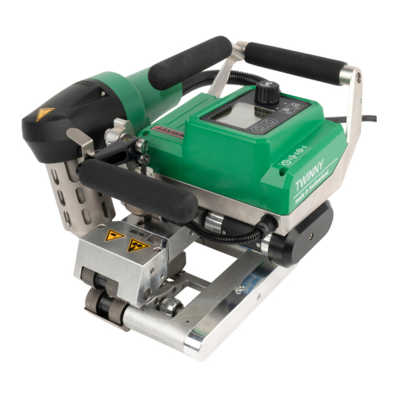
4.4 Übersicht Geräteteile 1. Netzanschlussleitung 12. Kontaktiersystem unten 2. Handgriffe 13. Schleppzunge 3. Bedienfeld 14. Kontaktiersystem oben 4. Spannhebel 15. Schweissdüse 5. Arretierung Spannhebel 16. Laufrolle vorne 6. Fügekraftmodul 17. Einschwenkmechanik 7. Spannarm 18. Arretierung Heissluftgebläse 8. Pendelkopf 19. Heissluftgebläse 9. -
Seite 9: Netzunterbruch
Das Gerät befindet sich nicht im Schweisspro- Das Gerät startet und auf dem Display erscheint die Startanzeige. zess. 5. Bedienfeld TWINNY T7 5.1 Übersicht Bedienfeld TWINNY T7 22. Taste "Auf" 23. Taste "Ab" 24. Taste Heizung "Ein/Aus" 25. Taste Antrieb "Ein/Aus"... -
Seite 10: Funktionstasten
5.2 Funktionstasten Aktuelle Auswahl Aktuelle Auswahl Aktuelle Auswahl Tastaturmodus Setup-Menü Funktionsanzeige Arbeitsanzeige Verändern der Position Wechseln von Auf (22) Verändert die Position inner- innerhalb der Arbeits- Funktionsanzeige in Ab (23) halb des Setup-Menüs. anzeige. Arbeitsanzeige. Heizung Schaltet Heizung Schaltet Heizung Keine Funktion Ein/Aus (24) ein/aus... -
Seite 11: Anzeigesymbole Der Statusanzeige
Antrieb Die LED der Taste Antrieb "Ein/Aus" (25) zeigt den Zustand des Antriebs an. LED-Status (26) Zustand Ursache Heizung Ein/Aus (24) LED aus Antrieb ist ausgeschaltet LED dauernd grün Antrieb ist eingeschaltet Tritt während des Betriebes des Antriebs eine Warnmeldung in der Statusanzeige Bereich 2 (31) auf oder eine Fehlermeldung in der Arbeitsanzeige (29), wird diese wie folgt dargestellt: LED blinkt rot Antrieb Strombegrenzung ist aktiv. -
Seite 12: Anzeigesymbole Der Arbeitsanzeige
(klein) dargestellt. Standard-Einstellung ab Werk. Ist Set Values deaktiviert, erscheinen im Betrieb nur die Ist-Werte (gross) ansonsten °C nur die Soll-Werte (gross). Abkühlvorgang (Cool Down Mode) Fehlermeldung Hardware (Heizelement defekt). Das Gerät ist nicht mehr einsatzbereit. Kontaktieren Sie ein autorisiertes Leister Service-Center. -
Seite 13: Setup-Menü Vom Bedienfeld Des Twinny T7
6. Setup-Menü vom Bedienfeld des TWINNY T7 6.1 Übersicht Menüführung Nur im «Advanced Mode» verfügbar... -
Seite 14: Schweissrezepte Einrichten, Speichern Und Auswählen (Save Recipes)
6.2 Schweissrezepte einrichten, speichern und auswählen (Save Recipes) Ihr TWINNY T7 verfügt über neun frei definierbare Rezepte und über das Rezept „BASIC“ Mit Save Recipes können Sie die Sollwerteinstellungen der Schweissparameter Antrieb, Lufttemperatur und Luft- menge unter einer frei wählbaren Bezeichnung abspeichern (siehe Eingeben von Rezeptnamen). -
Seite 15: Eingeben Von Rezeptnamen
Rezeptwahl • Durch Anwählen des Icons „Freie und vordefinierte Rezepte anwählen“ in der Funktionsanzeige (28) gelangen Sie ins Menü „Select Recipes“. • Setzen Sie den Cursor mit den Tasten „Auf“ und „Ab“ (22/23) auf das gewünschte Rezept und bestätigen Sie mit dem «e-Drive»... -
Seite 16: Bereitschaftsmodus (Standby)
Die Funktionen von „Kap. Duty Info“ bis „Kap. Reset to defaults“ sind nur im Advanced Mode verfügbar. 6.6 Duty Info Unter Duty Info erhalten Sie Angaben zur Laufzeit Ihres TWINNY T7. Gehen Sie mit dem «e-Drive» (27) ins Menü Einstellungen und bestätigen Sie Ihre Wahl. Stellen Sie nun mit dem «e-Drive»... -
Seite 17: General Info
6.7 General Info Unter General Info stehen Ihnen Versionsinformationen zur Software, sowie Angaben zum Produktionszeitpunkt zur Verfügung. Gehen Sie mit dem «e-Drive» (27) ins Menü Einstellungen und bestätigen Sie Ihre Wahl. Stellen Sie mit dem «e-Drive» (27) den Advanced Mode auf On und wählen Sie nun General Info. -
Seite 18: Set Values
6.11 Set Values Wenn Sie die Funktion Set Values aktiviert haben, wird die Ist-Temperatur (gross) und die Soll-Temperatur (klein) in der Arbeitsanzeige (29) dargestellt. Dies gilt in analoger Form für die Antriebsgeschwindigkeit (m/min). Ist die Funktion deaktiviert, werden nur die Sollwerte dargestellt. -
Seite 19: Tastensperre
• Der Stundenzähler ist nun zurückgestellt. 6.14 Tastensperre Der TWINNY T7 verfügt über eine Tastensperre. Diese sperrt die vier Tasten und den «e-Drive» (27) auf dem Bedienfeld (3). Durch gleichzeitiges Drücken der Tasten "Auf" und "Ab" (22/23) während mindestens 2 Sek. - Seite 20 Für den Einsatz des Gerätes auf Baustellen ist ein FI-Schutzschalter zum Schutz des dort arbeitenden Personals zwingend erforderlich. Gerät starten • Schalten Sie den Heissluftschweissautomaten über den Hauptschalter (20) ein, wenn Sie die Arbeitsumgebung und den Heissluftschweissautomaten gemäss Beschreibung vorbereitet haben. •...
-
Seite 21: Schweissvorbereitung
Einstellen von Geschwindigkeit, Temperatur und Luftmenge vor dem Schweissen • Ist der Antrieb ausgeschalten, werden die Schweissparameter Temperatur, Luftmenge und Geschwindigkeit in der Arbeitsanzeige (29) wie folgt eingestellt: • Mit den Pfeiltasten "Auf" (22) und "Ab" (23) können Sie den Cursor auf die gewünschte Arbeitsanzeige (29) stellen. - Seite 22 Schweissung beginnen Bewegliche Teile dürfen nicht berührt werden. Es besteht die Gefahr von ungewolltem Erfassen und Einziehen. Keine losen Kleidungsstücke wie Schals oder Tücher tragen. Langes Haar zusammenbinden und durch eine Kopfbedeckung schüt- zen. Verbrennungsgefahr Heizelementrohr und Düse nicht im heissen Zustand berühren. Das Gerät stets zuerst abkühlen lassen.
-
Seite 23: Gerät Ausschalten
7.5 Gerät ausschalten • Schalten Sie Antrieb und Heizung mit den Tasten Antrieb Ein/Aus (25) und Heizung Ein/Aus (24) aus. Die Taste Heizung Ein/Aus (24) muss 2 Sek. gedrückt gehalten werden. • Die Anzeige „Heating off“ erscheint auf dem Display und das Gerät wechselt in den Cool down mode (siehe Cool down mode). -
Seite 24: Warnung Und Fehlermeldung (Twinny T7)
8. Warnung und Fehlermeldung (TWINNY T7) Warn- und Fehlermeldungen werden fallweise in der Statusanzeige (31) oder in der Arbeitsanzeige (29) darge- stellt. Liegt eine Warnung vor, können Sie weitgehend ohne Einschränkung weiterarbeiten. Beim Auftreten einer Fehlermeldung können Sie jedoch nicht mehr weiterarbeiten. Die Heizung wird automatisch aus-, das Gebläse eingeschaltet und der Antrieb wird blockiert. - Seite 25 0004.XXXX Fehler Hardware 0008.XXXX Thermoelement defekt Fehler 0200.XXXX Fehler Kommunikationsmodul 0400.XXXX Fehler Antrieb Leister Service-Center kontaktieren...
-
Seite 26: Bedienfeld Twinny T5
9. Bedienfeld TWINNY T5 37. Taste Antrieb „Ein/Aus“ mit Status-LED 38. Taste Heizung „Ein/Aus“ mit Status-LED 39. Taste „Minus“ 40. Taste „Bestätigen“ 41. Taste „Plus“ 42. Anzeigefelder Die Ist-Werte werden gross, die Sollwerte klein dargestellt. Am linken Rand befindet sich der Coursor am rechten Rand die Parametereinheit. -
Seite 27: Einstellen Der Parametereinheiten
Antrieb Die LED der Taste Antrieb "Ein/Aus" (37) zeigt den Zustand des Antriebs an. LED-Status Zustand Antrieb Ein/Aus (37) LED aus Antrieb ist ausgeschaltet LED dauernd grün Antrieb ist eingeschaltet Heizung und Antrieb Blinken die beiden LED der Taste Heizung "Ein/Aus" (38) und der Taste Antrieb "Ein/Aus" (37) gleichzeitig, so liegt ein Fehler vor (siehe Kapitel Fehlermeldung). -
Seite 28: Inbetriebnahme Twinny T5
10. Inbetriebnahme TWINNY T5 10.1 Arbeitsumgebung und Sicherheit Der Heissluftschweissautomat darf nur im Freien oder in gut belüfteten Räumen eingesetzt werden. Setzen Sie den Heissluftschweissautomaten niemals in explosionsgefährdeter oder leicht entzündbarer Umgebung ein und halten Sie stets Abstand zu brennbaren Materialien oder explosiven Gasen. Lesen Sie das Material-Sicherheits-Datenblatt des Materialherstellers und befolgen Sie dessen Anwei- sungen. - Seite 29 ACHTUNG! Bei Überschreiten der maximalen Fügekraft von 1000N können mechanische Beschädigungen auftreten Quetschgefahr Durch mechanisch bewegte Teile besteht Quetschgefahr. Halten Sie den Heissluftschweissautomaten ausschliesslich an den dafür vorgesehenen Griffen. Einstellen der Fügekraft Das Fügekraftmodul (6) am TWINNY T5 verhindert beim Schweissen von Materialdicken bis 3 mm, dass eine zu grosse Fügekraft eingestellt werden kann.
-
Seite 30: Schweissvorbereitung
10.3 Schweissvorbereitung • Die maximale Überlappbreite beträgt 125 mm • Die Dichtungsbahnen müssen zwischen der Überlappung sowie der Ober- und Unterseite sauber und trocken sein. 10.4 Schweissablauf • Bevor der Schweissautomat eingesetzt wird, sind Testschweissungen gemäss Schweiss- anleitung des Materialherstellers und nationaler Normen oder Richtlinien vorzunehmen. Die Testschweissungen müssen geprüft werden. -
Seite 31: Gerät Ausschalten
Während der Schweissung • Der Heissluftschweissautomat kann während dem Schweissvorgang über die Handgriffe (2), den Spannhebel (4) oder dem optionalen Führungsstab entlang der Überlappung geführt werden. • Schweissgeschwindigkeit, Luftmenge und Lufttemperatur können während dem Schweissen jederzeit verändert werden (siehe Kapitel Einstellen von Geschwindigkeit, Temperatur und Luftmenge). Schweissung beenden •... -
Seite 32: Einstellungen Am Twinny T7/T5
12. Einstellungen am TWINNY T7/T5 Bevor Komponenten am Schweissautomaten demontiert oder montiert werden, muss das Gerät ab- gekühlt und der Hauptschalter ausgeschaltet sein. Die Netzanschlussleitung muss vom Netz getrennt sein. 12.1 Austausch Andrückrollen Je nach Anwendung können Sie unterschiedliche Antriebs-/Andrückrollen (9/11) am TWINNY verwenden (siehe Zubehör). -
Seite 33: Austausch Schweissdüse
12.2 Austausch Schweissdüse Je nach Anwendung können Sie unterschiedliche Schweissdüsen (15) am TWINNY verwenden (siehe Zubehör). Schwenken Sie das Heissluftgebläse (19) für den Austausch der Schweissdüse (15) in die Parkposition. Demontage der Schweissdüse (15): Reihenfolge Nr. 1 – 2 Montage der Schweissdüse (15): Umgekehrte Reihenfolge Nr. -
Seite 34: Montage Field-Kit
12.3 Montage Field-Kit Wenn für den Schweissautomaten mehr Bodenfreiheit oder grössere Laufrollen benötigt werden, können die Stan- dard Laufrollen durch das Field-Kit ersetzt werden. Demontage Laufrolle vorne (16): Reihenfolge Nr. 1 – 2 Montage Field-Kit vorne: Reihenfolge Nr. 3 – 8 Demontage Field-Kit vorne: Reihenfolge Nr. -
Seite 35: Zubehör
Schweissautomat von einer autorisierten Leister-Service-Stelle kontrolliert werden. 15. Schulung • Die Leister Technologies AG sowie deren autorisierte Service-Stellen bieten Kurse für diverse Anwendungen an. 16. Gewährleistung • Für dieses Gerät gelten die vom direkten Vertriebspartner/Verkäufer gewährten Garantie- oder Gewährleis- tungsrechte ab Kaufdatum. - Seite 36 5.5 Display symbols of the function display ..................44 5.6 Display symbols of the working display ..................45 6. Setup menu on the TWINNY T7 control panel ..................46 6.1 Menu navigation overview ......................46 6.2 Setting up, saving, and selecting recipes (Save Recipes) ..............47 6.3 Entering recipe names .........................
- Seite 37 10.4 Welding sequence ........................63 10.5 Switching off the device ....................... 64 11. Error messages........................... 64 12. Settings on the TWINNY T7/T5 ......................65 12.1 Replacement of pressure rollers ....................65 12.2 Replacing the welding nozzle ....................... 66 12.3 Assembling the field kit ....................... 67 12.4 Assembling the guide bar ......................
-
Seite 38: Important Safety Instructions
Do not pass the device on to anyone else without the operating instructions. LEISTER TWINNY T7/T5 automatic welder You can find more information on the TWINNY and the myLeister app at www.leister.com. 1. Important safety instructions Please ensure that you observe the safety instructions provided in the individual chapters of these operating instructions as well as the following provisions. -
Seite 39: Intended Use
1.1 Intended use TWINNY T7/T5 is intended for lap welding and the assembly of films and sealing sheets. The maximum overlap width is 125 mm. The maximum welding seam width is 50 mm. Only use original Leister spare parts and accessories; otherwise, any warranty or guarantee claims will be invali- dated. -
Seite 40: Transport
The model and serial number are indicated on your device's type plate (21). Please transfer this information to your operating instructions. In the event of any inquiries to our representatives or authorized Leister Service Centers, please always refer to this information. Model:................................ -
Seite 41: Overview Of Device Parts
4.4 Overview of device parts 1. Power cord 12. Contacting system, lower 2. Handles 13. Towing bar 3. Control panel 14. Contacting system, upper 4. Clamping lever 15. Welding nozzle 5. Clamping lever lock 16. Track roller, front 6. Welding force module 17. -
Seite 42: Power Supply Interruption
The device is not welding. - The device starts up and the start display appears on the display. 5. TWINNY T7 control panel 5.1 Overview of the TWINNY T7 control panel 22. "Up" key 23. "Down" key 24. Key for heating "On/Off"... -
Seite 43: Function Keys
5.2 Function keys Current selection Current selection Current selection Keyboard mode Setup menu function display Working display Changes the position Switches from Up (22) Changes the position within within the working function display to Down (23) the Setup menu display working display Heating Switches heating... -
Seite 44: Display Symbols Of The Status Display
Drive The LED on the Drive "On/Off" key (25) displays the condition of the drive. LED status (26) Condition Cause Drive On/Off (25) LED off Drive is switched off LED continuously green Drive is switched on If, during operation of the drive, a warning message occurs in the status display "Section 2" (31) or if there is an error message in the working display (29), then this will be displayed as follows: LED flashes red Drive current limiting is active... -
Seite 45: Display Symbols Of The Working Display
If Set Values is deactivated, then only the actual values (large) are displayed during °C operation, otherwise only the setpoint values (large). Cool down mode Hardware error message (heating element faulty). The device is no longer ready for operation. Contact an authorized Leister Service Center. -
Seite 46: Setup Menu On The Twinny T7 Control Panel
6. Setup menu on the TWINNY T7 control panel 6.1 Menu navigation overview Only available in "Advanced Mode"... -
Seite 47: Setting Up, Saving, And Selecting Recipes (Save Recipes)
6.2 Setting up, saving, and selecting recipes (Save Recipes) Your TWINNY T7 has nine freely definable recipes and the "BASIC" recipe. "Save Recipes" can be used to save the setpoint settings for the drive, air temperature, and air volume welding parameters under a freely selectable designation (see Entering recipe names). -
Seite 48: Entering Recipe Names
Selecting a recipe • Choosing the "Select freely definable and predefined recipes" icon in the function display (28) takes you to the "Select Recipes" menu. • Use the "Up" and "Down" (22/23) keys to position the cursor on the desired recipe and press "e-Drive" (27) to confirm. -
Seite 49: Standby
The functions listed in Chapters "Duty Info" to "Reset to defaults" are only available in Advanced Mode. 6.6 Duty Info Under Duty Info you will find information regarding the runtime of your TWINNY T7. Use the "e-Drive" (27) to access the Setup menu and confirm your selection. Now use the "e-Drive" (27) to set the Advanced Mode to On and then select Duty Info. -
Seite 50: Duty Info
6.7 Duty Info Under General Info you will find version information regarding the software in addition to information regarding the date of production. Use the "e-Drive" (27) to access the Setup menu and confirm your selection. Use the "e-Drive" (27) to set the Advanced Mode to On and then select General Info. 6.8 Warnings Warnings are displayed on a case-by-case basis in the status display (31). -
Seite 51: Set Values
6.11 Set Values If you have activated the Set Values function, then the actual temperature (large) and the setpoint temperature (small) will be presented in the working display (29). This will be in the analog form for the drive speed (m/min). If the function has been deactivated, only the setpoint values are displayed. -
Seite 52: Key Lock
6.14 Key lock The TWINNY T7 has a key lock. This blocks the four keys and the "e-Drive" (27) on the control panel (3). The key lock is activated or deactivated by simultaneously pressing the "Up" and "Down" keys (22/23) for at least 2 seconds. - Seite 53 If the device is being used on construction sites, a residual-current circuit breaker must be used to protect site personnel. Starting the device • Once you have prepared the work environment and the hot-air welder in accordance with the description, switch on the hot-air welder using the main switch (20). •...
-
Seite 54: Preparation For Welding
Setting the speed, temperature, and air volume before welding • If the drive is switched off, then the welding parameters for temperature, air volume, and speed are set as follows in the working display (29): • Using the "Up" (22) and "Down" (23) arrow keys, you can set the cursor to the desired working display (29). - Seite 55 Commencing welding Moving parts must not be touched. There is a risk of inadvertently becoming caught and being pulled in. Do not wear articles of clothing such as scarves or shawls. Tie up long hair or protect it by wearing headgear. Risk of burning Do not touch heating element tube and nozzle when they are hot.
-
Seite 56: Switching Off The Device
7.5 Switching off the device • Switch the drive and heating off using the Drive On/Off (25) and Heating On/Off (24) keys. The Heating On/Off (24) key must be held down for 2 seconds. • The "Heating off" display appears and the device switches to Cool down mode (see Cool down mode). -
Seite 57: Warnings And Error Messages (Twinny T7)
8. Warnings and error messages (TWINNY T7) Warning and error messages are displayed on a case-by-case basis in the status display (31) or in the working display (29). If there is a warning pending, you can still continue to work largely without restrictions. - Seite 58 0004.XXXX Hardware error 0008.XXXX Thermocouple is defective Error 0200.XXXX Communication module error 0400.XXXX Drive error Contact Leister Service Center...
-
Seite 59: Twinny T5 Control Panel
9. TWINNY T5 control panel 37. Drive "On/Off" key with status LED 38. Heating "On/Off" key with status LED 39. "Minus" key 40. "Confirm" key 41. "Plus" key 42. Display fields The actual values are displayed in large font and the setpoint values in small font. The cursor is located on the left-hand side and the parameter unit on the right-hand side. -
Seite 60: Setting The Parameter Units
Drive The LED on the Drive "On/Off" key (37) displays the condition of the drive. LED status Condition Drive On/Off (37) LED off Drive is switched off LED continuously green Drive is switched on Heating and drive If the two LEDs for the Heating "On/Off" (38) key and the Drive "On/Off" (37) key flash simultaneously, an error is pending (see Chapter Error messages). -
Seite 61: Commissioning The Twinny T5
10. Commissioning the TWINNY T5 10.1 Work environment and safety The hot-air welder must only be used in the open or in a well-ventilated area. Never use the hot-air welder in explosive or readily inflammable surroundings and maintain sufficient distance from combustible materials or explosive gases at all times. Read the material safety data sheet of the manufacturer of the material and follow that company's instructions. - Seite 62 CAUTION! Mechanical damage could occur if the maximum welding force of 1000 N is exceeded Risk of crushing There is a risk of crushing due to the movement of mechanical parts. Only hold on to the hot-air welder at the handles provided. Adjusting the welding force When welding materials up to a thickness of 3 mm, the welding force module (6) on the TWINNY T5 prevents an excessive welding force from being set.
-
Seite 63: Preparation For Welding
10.3 Preparation for welding • The maximum overlap width is 125 mm. • The sealing sheets must be clean and dry between the overlaps and on the upper and lower side. 10.4 Welding sequence • Before the automatic welder is used, test welds are to be carried out in accordance with the welding instructions of the material manufacturer and with national standards or guide- lines. -
Seite 64: Switching Off The Device
During welding • During the welding process, the hot-air welder can be guided along the overlap using the handles (2), the clamping lever (4), or the optional guide bar. • The welding speed, air volume, and air temperature can be adjusted at any time during welding (see Chapter Setting the speed, temperature, and air volume). -
Seite 65: Settings On The Twinny T7/T5
12. Settings on the TWINNY T7/T5 The device must have cooled down and the main switch must have been switched off before components on the automatic welder are dismantled or assembled. The power cord must have been disconnected from the power supply. -
Seite 66: Replacing The Welding Nozzle
12.2 Replacing the welding nozzle Depending on the application, you can use different welding nozzles (15) on the TWINNY (see Accessories). Swivel the hot-air blower (19) into the park position to replace the welding nozzle (15). Dismantling the welding nozzle (15): Sequence no. -
Seite 67: Assembling The Field Kit
12.3 Assembling the field kit If a greater floor clearance or larger track rollers are required for the automatic welder, the standard track rollers can be replaced by the field kit. Dismantling the front track roller (16): Sequence no. 1 – 2 Assembling the front field kit: Sequence no. -
Seite 68: Accessories
13. Accessories • Only use original Leister spare parts and accessories; otherwise, any warranty or guarantee claims will be invalidated. • You can find more information at www.leister.com. 14. Service and repair • Repairs shall be assigned exclusively to authorized Leister Service Centers. - Seite 69 5.5 Simboli visualizzati nella schermata funzioni .................. 77 5.6 Simboli visualizzati della schermata del processo ................78 6. Menù Setup del pannello di comando del TWINNY T7 ................79 6.1 Panoramica della gestione menù ....................79 6.2 Configurare, salvare e selezionare ricette di saldatura (Save Recipes) ..........80 6.3 Immissione dei nomi delle ricette ....................
- Seite 70 10.4 Esecuzione della saldatura ......................96 10.5 Spegnimento dell’apparecchio ..................... 97 11. Messaggi di errore ..........................97 12. Impostazioni sul TWINNY T7/T5 ......................98 12.1 Sostituzione rulli di pressione ...................... 98 12.2 Sostituzione ugello di saldatura ....................99 12.3 Montaggio Field-Kit ........................100 12.4 Montaggio barra di guida ......................
-
Seite 71: Avvertenze Importanti Per La Sicurezza
Se affidato a terzi, il prodotto deve essere sempre provvisto delle istruzioni per l’uso. LEISTER TWINNY T7/T5 Saldatrice automatica Ulteriori informazioni sul TWINNY e sull’app myLeister sono disponibili nel sito www.leister.com 1. Avvertenze importanti per la sicurezza Osservare sempre le indicazioni tecniche di sicurezza contenute nei vari capitoli di queste istruzioni per l’uso nonché... -
Seite 72: Utilizzo Conforme
1.1 Utilizzo conforme TWINNY T7/T5 è stato progettato per la saldatura a sovrapposizione e il confezionamento di pellicole e guaine di impermeabilizzazione. La larghezza massima di sovrapposizione è di 125 mm. La larghezza massima del cordone di saldatura ammonta a 50 mm. -
Seite 73: Trasporto
Numero di matricola: ............................Esempio: 4.2 Dotazione di fornitura (attrezzatura standard nella cassa) 1 × apparecchio TWINNY T7/T5 (a seconda della configurazione) • 1 × spazzola metallica • 1 × istruzioni per l’uso originali • 1 × traduzione delle istruzioni per l’uso originali 4.3 Accessori opzionali... -
Seite 74: Panoramica Delle Parti Dell'apparecchio
4.4 Panoramica delle parti dell'apparecchio 1. Cavo di alimentazione 12. Sistema di contatto sotto 2. Impugnature 13. Linguetta di tiro 3. Pannello di comando 14. Sistema di contatto sopra 4. Leva di serraggio 15. Ugelli di saldatura 5. Bloccaggio leva di serraggio 16. -
Seite 75: Interruzione Dell'alimentazione
L’apparecchio si avvia e sul Display appare la schermata di trova nel processo di inizio. saldatura. 5. Pannello di comando TWINNY T7 5.1 Panoramica pannello di comando TWINNY T7 22. Tasto “Su” 23. Tasto “Giù” 24. Tasto riscaldamento “Acc. / Spento” 25. Tasto motore “Acc. / Spento”... -
Seite 76: Tasti Funzione
5.2 Tasti funzione Selezione corrente Selezione corrente Selezione corrente Funzione tastiera Schermata del Menu Set-up schermata funzioni processo Cambio della scher- Su (22) Cambio di posizione nella Modifica la posizione nel menu mata funzioni nella Giù (23) schermata del processo. Setup. -
Seite 77: Simboli Visualizzati Nella Schermata Di Stato
Azionamento Il LED del tasto Motore “acc./spento” (25) indica lo stato del motore. Stato LED (26) Stato Causa Motore acc./spento (25) LED spento Motore spento LED verde fisso Motore acceso Se durante il funzionamento del motore viene emesso un messaggio di avviso nella schermata di stato Campo 2 (31) o un messaggio di errore nella schermata del processo (29), esso è... -
Seite 78: Simboli Visualizzati Della Schermata Del Processo
Se si disattiva “Set Values” [Imposta valori], durante l’esercizio compaiono solo i °C valori reali (in grande), altrimenti solo i valori nominali (in grande). Processo di raffreddamento (Cool Down Mode) Messaggio di errore hardware (elemento riscaldante difettoso). L'apparecchio non è più utilizzabile! Contattare un centro assistenza autorizzato da Leister. -
Seite 79: Menù Setup Del Pannello Di Comando Del Twinny T7
6. Menù Setup del pannello di comando del TWINNY T7 6.1 Panoramica della gestione menù Disponibile solo in “modalità avanzata”... -
Seite 80: Configurare, Salvare E Selezionare Ricette Di Saldatura (Save Recipes)
6.2 Configurare, salvare e selezionare ricette di saldatura (Save Recipes) Il TWINNY T7 dispone di nove ricette personalizzabili e della ricetta “BASIC” Con “Save Recipes” [Salva ricette] è possibile salvare le impostazioni dei valori nominali dei parametri di saldatu- ra, azionamento, temperatura dell'aria e portata d'aria con una denominazione selezionabile liberamente (vedere Immissione del nome della ricetta). -
Seite 81: Immissione Dei Nomi Delle Ricette
Selezione della ricetta • Selezionando il simbolo “Selezione di ricette predefinite e personalizzate” nella schermata funzioni (28) si apre il menù “Select recipes” [Seleziona ricette]. • Con i tasti “Su” e “Giù” (22/23) posizionare il cursore sulla ricetta desiderata e confermare con l’«e-Drive» (27). -
Seite 82: Modalità Di Attesa (Standby)
Le funzioni da “Cap. Duty Info” fino a “Reset to defaults” sono disponibili solo nell'Advanced Mode. 6.6 Duty Info [Info servizio] Alla voce Duty Info [Info servizio] sono reperibili i dati relativi alla durata di esercizio del TWINNY T7. Con l’«e-Drive» (27) passare al menù Setup [Impostazioni] e confermare la propria selezione. Impostare quindi con l’«e-Drive»... -
Seite 83: General Info
6.7 General Info Alla voce General Info [Info generali] sono disponibili le informazioni sulla versione del software nonché i dati relativi alla data di produzione. Con l’«e-Drive» (27) passare al menù Setup [Impostazioni] e confermare la propria selezio- ne. Con l’«e-Drive» (27) impostare Advanced Mode su On e selezionare General Info [Info generali]. -
Seite 84: Set Values [Valori Impostati]
6.11 Set Values [Valori impostati] Se la funzione Set Values è attivata, vengono visualizzate la temperatura reale (in grande) e quella nominale (in piccolo) nella schermata del processo (29). Questo vale allo stesso modo per la velocità di azionamento (m/min). Se la funzione è disattivata, vengono visualiz- zati solo i valori nominali. -
Seite 85: Blocco Tasti
6.14 Blocco tasti Il TWINNY T7 dispone di un blocco dei tasti. Il blocco blocca i quatto tasti e l'«e-Drive» (27) sul pannello di comando (3). Premendo contemporaneamente i tasti freccia “Su” e “Giù” (22/23) per almeno 2 secondi, viene attivato o disattivato il blocco tasti. - Seite 86 Se l’apparecchio viene usato in cantiere, per garantire la sicurezza del personale è assolutamente necessario un interruttore differenziale (salvavita). Avviamento dell'apparecchio • Attivare la saldatrice automatica ad aria calda con l'interruttore principale (20), dopo aver preparato l’ambiente di lavoro e la saldatrice automatica ad aria calda attenendosi alle indicazioni riportate.
-
Seite 87: Preparazione Alla Saldatura
Impostazione di velocità, temperatura e quantità d’aria prima della saldatura • Se il motore è spento, i parametri di saldatura Temperatura, Quantità d’aria e Velocità nella schermata di processo (29) vanno impostati nel modo seguente: • Con i tasti freccia “Su” (22) e “Giù" (23) è possibile posizionare il cursore sulla schermata di processo (29) desiderata. - Seite 88 Inizio della saldatura Non toccare le parti mobili: vi è il pericolo di rimanere incastrati o impigliati. Non indossare capi d’abbigliamento larghi come sciarpe e foulard. Legare i capelli lunghi e proteggerli con un copricapo. Pericolo di ustioni Non toccare il tubo dell’elemento riscaldante e l’ugello quando sono roventi. Lasciar raffreddare prima l’apparecchio.
-
Seite 89: Spegnimento Dell'apparecchio
7.5 Spegnimento dell’apparecchio • Spegnere il motore e il riscaldamento con i tasti Motore acc./spento (25) e Riscal- damento acc./spento (24). Il tasto Riscaldamento acc./spento (24) va tenuto premuto per 2 sec. • Il display visualizza “Heating off” [Riscaldamento spento] e l’apparecchio passa al Cool down mode (vedi Cool down mode). -
Seite 90: Avvertenze E Messaggi Di Errore (Twinny T7)
8. Avvertenze e messaggi di errore (TWINNY T7) Le avvertenze e i messaggi di errore vengono visualizzati caso per caso nella schermata di stato (31) o nella schermata del processo (29). Se compare un’avvertenza, è possibile proseguire con il lavoro senza limitazioni. - Seite 91 0004.XXXX Errore hardware 0008.XXXX Malfunzionamento della termocoppia Errore 0200.XXXX Errore modulo di comunicazione 0400.XXXX Errore motore Contattare il centro assistenza Leister...
-
Seite 92: Pannello Di Comando Twinny T5
9. Pannello di comando TWINNY T5 37. Tasto Motore “acc./spento” con LED di stato 38. Tasto Riscaldamento “acc./spento” con LED di stato 39. Tasto “Meno” 40. Tasto “Conferma” 41. Tasto “Più” 42. Campi di visualizzazione I valori reali vengono visualizzati in grande, quelli nominali in piccolo. -
Seite 93: Impostazione Delle Unità Dei Parametri
Azionamento Il LED del tasto Motore “acc./spento” (37) indica lo stato del motore. Stato LED Stato Motore acc./spento (37) LED spento Motore spento LED verde fisso Motore acceso Riscaldamento e motore Se i due LED del tasto Riscaldamento “acc./spento” (38) e del tasto Motore “acc./spento” (37) lampeggiano contemporaneamente, è... -
Seite 94: Messa In Servizio Twinny T5
10. Messa in servizio TWINNY T5 10.1 Ambiente di lavoro e sicurezza La saldatrice automatica ad aria calda è progettata per essere utilizzata esclusivamente all’aperto oppure all’interno di locali ben aerati. Non impiegare mai la saldatrice automatica ad aria calda in ambienti o aree a rischio di esplosione o in cui sia presente un rischio di infiammabilità... - Seite 95 ATTENZIONE: In caso di superamento della forza di giunzione massima di 1000 N possono verificarsi danni meccanici Pericolo di schiacciamento Pericolo di schiacciamento causato dalle parti azionate meccanicamente. Utilizzare esclusivamente le apposite maniglie per tenere la saldatrice automatica ad aria calda. Regolazione della forza di giunzione Il modulo forza di giunzione (6) del TWINNY T5 impedisce l’impostazione di una forza di giunzione eccessiva durante la saldatura di spessori di materiale fino a 3 mm.
-
Seite 96: Preparazione Alla Saldatura
10.3 Preparazione alla saldatura • La larghezza massima di sovrapposizione è di 125 mm • Le guaine di impermeabilizzazione devono essere pulite e asciutte tra la sovrapposizione e sul lato inferiore e quello superiore. 10.4 Esecuzione della saldatura • Prima di utilizzare la saldatrice automatica, è necessario svolgere saldature di prova in conformità... -
Seite 97: Spegnimento Dell'apparecchio
Durante la saldatura • Durante il processo di saldatura è possibile guidare la saldatrice ad aria calda lungo la sovrapposizione serven- dosi delle maniglie (2), della leva di serraggio (4) o della barra di guida opzionale. • La velocità di saldatura, la quantità d’aria e la temperatura dell’aria possono essere modificate in ogni momen- to durante la saldatura (vedi capitolo Impostazione di velocità, temperatura e quantità... -
Seite 98: Impostazioni Sul Twinny T7/T5
12. Impostazioni sul TWINNY T7/T5 Prima dello smontaggio o del montaggio di componenti della saldatrice automatica, l’apparecchio deve essere raffreddato e l’interruttore principale disinserito. Il cavo di collegamento deve essere scollegato dalla rete elettrica. 12.1 Sostituzione rulli di pressione A seconda dell’applicazione, è possibile utilizzare diversi rulli di azionamento/pressione (9/11) sul TWINNY (vedi Accessori). -
Seite 99: Sostituzione Ugello Di Saldatura
12.2 Sostituzione ugello di saldatura A seconda dell’applicazione, è possibile utilizzare diversi ugelli di saldatura (15) sul TWINNY (vedi Accessori). Ruotare il soffiante dell’aria calda (19) nella posizione di attesa per sostituire l’ugello di saldatura (15). Smontaggio dell’ugello di saldatura (15): Sequenza n. -
Seite 100: Montaggio Field-Kit
12.3 Montaggio Field-Kit Se per la saldatrice automatica si necessita di una maggiore altezza da terra o di ruote più grandi, le ruote stan- dard possono essere sostituite con il Field-Kit. Smontaggio ruota anteriore (16): Sequenza n. 1 – 2 Montaggio Field-Kit anteriore: Sequenza n. -
Seite 101: Accessori
Leister autorizzato. 15. Formazione • La Leister Technologies AG e i rispettivi centri di assistenza autorizzati offrono corsi gratuiti per varie applicazioni. 16. Garanzia legale • A questo prodotto si applicano i diritti previsti per la garanzia concessi dal partner di distribuzione/rivenditore diretto, a partire dalla data di acquisto. - Seite 104 ® © Copyright by Leister Your authorised Service Centre is: Leister Technologies AG Galileo-Strasse 10 CH-6056 Kaegiswil/Switzerland Tel. +41 41 662 74 74 +41 41 662 74 16 www.leister.com sales@leister.com...