Herunterladen Inhalt Inhalt Diese Seite drucken
Inhaltsverzeichnis

Werbung

Verfügbare Sprachen

Verfügbare Sprachen

8226
Inductive Conductivity Transmitter
Instruction Manual
Pneutrol International Limited
Unit 173 Argyle Industrial Estate, Argyle Street, Nechells, Birmingham B7 5TE
www.pneutrolfluidcontrol.com sales@pneutrol.com
Tel: +44 (0) 1213287288

Werbung

Inhaltsverzeichnis

Fehlerbehebung

loading

Inhaltszusammenfassung für bürkert 8226

  • Seite 1 8226 Inductive Conductivity Transmitter Instruction Manual Pneutrol International Limited Unit 173 Argyle Industrial Estate, Argyle Street, Nechells, Birmingham B7 5TE www.pneutrolfluidcontrol.com sales@pneutrol.com Tel: +44 (0) 1213287288...
  • Seite 2: Inhaltsverzeichnis

    Conductivity Simulation .............................34 4.5.6 Calibration of the Zero Point .............................34 8226 Settings....................................35 4.6.1 Factory setting of Conductivity Transmitter 8226 ....................35 4.6.2 User setting of 8226 Conductivity Transmitter ....................35 MAINTENANCE Storing and Cleaning of the Sensor ............................36 Trouble Shooting Guide ..............................36-37 ANNEX Specifications ..................................
  • Seite 3: Introduction

    Always ensure that the power supply is switched off before working on the device / system. If these instructions are ignored, no liability will be accepted and the guarantee on the device and accessories will become invalid. 8226...
  • Seite 4: Quickstart

    QUICK START This section provides a comprehensive installation and operation guide which will assist with the commissioning of the 8226 Conductivity Transmitter. INSTALLATION Unpacking Verification of items recieved Verify Contact your local Bürkert subsi- See section 6.5 order code diary.
  • Seite 5: Programming

    1 & 2 (if available) Choose the Normally filter 2 is sufficient for See section 4.4.7 desired filter most applications. See the next page. Mesure ou Simulation (option) The actions which are highlighted in grey must be fully completed for accurate measurement. 8226...
  • Seite 6: Testing

    <10µS/cm Install the unit Calibrate the unit to the fitting within the air This is optional although it is Simulation of See Section 4.5.5 recommended for commissioning the outputs large systems. L‘unité est prête 8226...
  • Seite 7: Installation

    Mounting horizontally or vertically on a pipe. Mounting within a tank without agitation. Mounting within a tank with agitation. Fig. 3.1 8226 Transmitter positioning Select the appropriate installation position to avoid air bubbles or cavities. The device must be protected against constant heat radiation and other environmental influences such as magnetic fields or direct exposure to sunlight.
  • Seite 8: Installation

    INSTALLATION INSTALLATION The 8226 conductivity transmitter can be easily installed into pipes using our specially designed fitting system. Place the plastic nut 3 onto the fitting 4 and snap the plastic ring 2 into the guide - bush 5. Ensure that the sensor is fully inserted and sitting correctly, making sure that the lug 6 is aligned correctly onto the fitting and that the sensor housing 1cannot be rotated.
  • Seite 9: General Electrical Connection

    - Replace part [3]. : Earth - Tighten the cable gland [5]. - Place gasket [4] between the DIN43650 connector and the fixed connector of the 8226. - Connect the DIN 43650 connector to the 8226. - Tighten screw [1].
  • Seite 10: Vdc Without Relay, With Cable Gland

    The electronics within the 8226 allows a sourcing or sinking PLC to be connected. Position A (Fig 3.5) provides a sourcing configuration and Position B (Fig 3.6) a sinking configurati-...
  • Seite 11 The electronics within the 8226 allows a sourcing or sinking PLC to be connected. Position A (Fig 3.5) provides a sourcing configuration and Position B (Fig 3.6) a sinking configuration.
  • Seite 12: Connection Examples With The 8226

    CONNECTION EXAMPLES WITH A 8226 1 2 3 4 SW300 8226 Jumper 24 V= TopControl and diaphragm valve Example of a connection between the Conductivity Transmitter 8226 12-30 VDC with relays and the Top Control 8630 mounted on a diaphragm valve 2031. 8226...
  • Seite 13 INSTALLATION 24 V= 1 2 3 4 SW300 8226 Positioner 1067 Example of a connection between the Conductivity Transmitter 8226 12-30 VDC with relays and the 1067 positioner mounted on a diaphragm valve 2031. 8226...
  • Seite 14 1 2 3 4 24 V= 8226 (a) Conductivity (b) Setpoint Solenoid control valve with PI-controller 8624 Example of a connection between the Conductivity Transmitter 8226 12-30 VDC with relays and a solenoid valve with a 8624 PI controller. 8226...
  • Seite 15: Operating And Control Guide

    Access to the CALIBRATION MENU* ENTER 5 Seconds Access to the TEST MENU* ENTER 0..9 5 Seconds * Only available within the main menu. ENTER Key can be locked to avoid accidental or unauthorised access. For further information see section 3.3.2. 8226...
  • Seite 16: Menu Guide

    OPERATION MENU GUIDE The menu guide below will assist in quickly and easily finding a desired parameter and programming the 8226 conductivity transmitter. Indicates blinking digits. MAIN MENU ENTER 12.6 mS 0..9 0..9 20.6 °c ENTER 0..9 10.32 CALIBRATION MENU 0..9...
  • Seite 17 The relays are held in their previous states. Access to the alternative menus will be denied. The parameters within the main menu will flash. HOLD NO HOLD ENTER ENTER 0..9 12.6 mS HOLD YES ENTER 20.6 °C 0..9 10.32 mA HOLD ENTER 12.6 mS 8226...
  • Seite 18 Damping selection. There are ten different 4.4.7 FILTER steps available. (Range 0 to 9) Back to the operation mode; store the new parameters set. The following sections explain how to change the parameter values within the calibration menu above. 8226...
  • Seite 19: Calibration Menu

    The selection of units is confirmed by the Enter-key and becomes immediately active. The conductivity can be displayed with 0, 1, 2 or 3 decimal places but 4 digits will always be displayed. (µSiemens/cm are always expressed in integer values; Siemens/cm always with 3 decimal points). 8226...
  • Seite 20: Sensor Coefficient

    = 6.295 x 0.985 = 6.200 SENS.COEF. K=06.000 ENTER 0..9 T° COEFF K=06.200 ENTER Correction Factor Tables for the 8226 Transmitter Weld Ends Male / Female threaded ports True union and Solvent spigots Brass Stainless Steel PVDF 0,991 0,989 1,113...
  • Seite 21: Modification Of The Cell Constant

    - Old value for the programmed sensor coefficient. Cond - Value for the measured conductivity. Cond 8226 - Value for the conductivity indicated by the 8226 transmitter. Calibration with a solution of 10.00 mS Electric cell constant programmed = 6.295 Conductivity measured by the 8226 = 10.50 Elec cst new = 6.295 x 10.00 / 10.50 = 5.995...
  • Seite 22: Temperature Compensation Coefficient

    3) Teach-In function (TEACH-IN) This function allows the user to practically determine with the transmitter a compensati- on curve within the desired temperature range. From entering the temperature limits and starting measurement the conductivity transmitter automatically computes the compensation curve. 8226...
  • Seite 23: Linear Temperature Compensation (Linear)

    The linear compensation is only valid for temperatures > 0 °C For calculating the average compensation value α, the following equation can be used: α The fi gure below explains the signifi cance of the linear temperature compensation coeffi cient. 25 C Figure 4.1 - Linear Compensation 8226...
  • Seite 24: Automatic Temperature Compensation (Auto)

    The memorized compensation curve for NaCl applies for concentrations between 60mg/l (≅ 100µS) to 270 g/l (≅ 220mS). In most cases the compensation within this option will be sufficient for water and diluted solutions. 8226...
  • Seite 25: Teach-In Temperature Compensation (Teach-In)

    Teach-In option at any time by pressing for a duration of 5 sec. 0..9 T° COEFF TEACH IN T-= 000 ENTER ENTER 0..9 0..9 T-= 015 T+= 000 ENTER 0..9 T+=110 MEASURE ENTER T°= 065 CURRENT MEAS END ENTER 8226...
  • Seite 26: Current Output

    20= 00.00 0..9 RELAY 1 ENTER 20= 12.00 Select the measurement required for the output current, then enter the beginning of the measuring range. (4mA) Enter the end of the measuring range. (20mA) Figure 4.3 - Output Signal 8226...
  • Seite 27: Relay (Option)

    1+ and 2+ = the high settings for both relays Contact Invert no Delay = 0 s Delay = 2 s 2+ (8) 2- (6) mS/cm mS/cm 1- (2) 1+ (4) Invert yes Relay 1 Relay 2 DEL 2 S DEL 2 S 8226...
  • Seite 28 DEL1 = 000 Enter the delay (seconds), which will effect both thres- holds of relay 1 0..9 RELAY 2 ENTER DEL1 = 004 To deactivate a relay configuration the conductivity of the threshold 1+ and 1- must equal 0.00. 8226...
  • Seite 29: Relay 2

    2. FILTER ENTER DEL2 = 004 INV YES FILTER ENTER INV NO If the relay 2 is used as an alarm, ensure that the normally open state of the relay corresponds to a safe position of the process. 8226...
  • Seite 30: Filter Function

    From the diagram below it is possible to see how the different filters influence the conducti- vity output and display over time. C (mS/cm) Filter 3 t (s) C (mS/cm) C (mS/cm) Conductivity Filter 6 t (s) t (s) C (mS/cm) Filter 9 t (s) 8226...
  • Seite 31 OFFSET and SPAN. If one of the two values is inap- propriate, the device will automatically return to the „OFFSET“ parameter and new values must be entered. The following sections explain how to change and investigate the parameter values within the test menu above. 8226...
  • Seite 32: Test Menu

    Measure the generated current with an ammeter. If the displayed value is incorrect it can be corrected by entering the measured value on the ammeter. Adjustment range : + / - 0.5mA SPAN SP= 20.00 ENTER Enter the measured value 0..9 T° ADJUST SP= 19.96 ENTER 8226...
  • Seite 33: Temperature Adjustment

    TEST MENU 4.5.3 TEMPERATURE ADJUSTMENT The 8226 conductivity transmitter posseses a temperature probe within the sensor. The value from the temperature sensor can be adjusted by an offset for compensation of the when „T ADJUST“ is ENTER actual temperature gradients. To enter a desired offset press displayed within the test menu and enter the value.
  • Seite 34: Conductivity Simulation

    To calibrate the unit, hold the sensor in the air and select „CALIB YES“ and the unit will automatically perform a calibration test. CALIB CALIB NO ENTER ENTER CALIB YES CALIB 1 ENTER The measure for calibration continues for a duration of about 1 min. 8226...
  • Seite 35: 8226 Settings

    INFORMATION 8226 SETTINGS The 8226 Conductivity Transmitter is calibrated within the factory before delivery to the settings shown in the table below. 4.6.1 FACTORY SETTING OF CONDUCTIVITY TRANSMITTER 8226 Language: English Unit of conductivity: mS/cm Unit of temperature: °C Relay: 00.00...
  • Seite 36: Maintenance

    Error at each start-up? Return the device Display after validation of the menu (EEPROM failure) Configure the device again Failure at each validation of the menu? Return the device Display within the Teach-In mode? Perform the Teach-In again 4.4.4.3 8226...
  • Seite 37 Program the relay output threshold range? 3.3.3 again Relays correctly connected? 3.3.3 Connect relays Connection of relays 1 and 2 inverted? Connect relays accordingly Protection fuses for the relays OK? ---- Change the fuses Relay switches ON? Relay switches ‘ON’ 8226...
  • Seite 38: Specifications

    Relay output Output type Normally open relays Load DC: 250V = ; 3A AC: 250V ≅ ; 3A Life expectancy 100 000 cycles (minimum) Thresholds Hysteresis programmable according to the temperature or conductivity. Switching delay Programmable from 0...180 s 8226...
  • Seite 39 Immunity According to generic norm EN 50082.2 Output current accuracy +/- 2% according to Test ENV 50145 (only valid for 115/230 VAC with relay) Safety According to safety regulations for measuring instruments for regulation and laboratory NF EN 61010-1 8226...
  • Seite 40: Dimensions

    126 (4,96") Plug 2508: DIN43650 with cable gland cable gland 88 (3,46") 88 (3,46") 106 (4,06") 126 (4,96") Plug 2509: DIN43650 without cable gland with reduction NPT 1/2‘‘ reduction NPT 1/2‘‘ 88 (3,46") 88 (3,46") Variable dimensions (in mm) 8226...
  • Seite 41: Measuring Principle

    MEASURING PRINCIPLE Conductivity is the ability of a liquid / solution to conduct an electrical current. To measure the conductivity of a solution the 8226 conductivity transmitter uses the following principle: A voltage is connected to the primary magnetic coil.
  • Seite 42: Label Type 8226

    ANNEX LABEL TYPE 8226 Conductivity Type of transmitter Seal material Sensor material Serial number COND :8226-FPM-PVDF 0047 12-30 V = 250 mA 4-20 mA REL :48 VAC ; 75 VDC/3A Relay caracteristics Output current 431679 W4YUP Power supply Power/current consumption Factory internal N°...
  • Seite 43 PC Union nut 619204 PPA Union nut 440229 Set with 1 green FPM gasket + 1 black EPDM gasket 552111 (for the sensor) Inductive conductivity sensor with a PVDF sensor 427139 Inductive conductivity sensor with a PEEK sensor 440230 NPT 1/2 8226...
  • Seite 44 ANNEX 8226...
  • Seite 45 8226 Transmetteur de Conductivité Inductif Manuel utilisateur...
  • Seite 46 12-30 VDC sans relais, avec presse-étoupe ......................10 3.3.3 12-30 VDC avec relais et presse-étoupe ........................10 3.3.4 115/230 VAC sans relais, avec presse-étoupe ......................11 3.4 Connexions possibles avec d’autres produits Burkert ......................12 3.4.1 Connexion avec un TopControl 8630 ........................12 3.4.2 Connexion avec un positionneur 1067 ........................13 3.4.3...
  • Seite 47: Introduction

    Respectez les consignes de sécurité lors des manipulations, de la maintenance ou de la réparation de l‘appareil. Ne pas intervenir lorsque l‘appareil/système est sous tension. Nous déclinons toute responsabilité en cas de non respect de ces instructions et dénonçons toute clause de garantie. 8226...
  • Seite 48: Quickstart

    QUICKSTART Cette section constitue un guide d‘installation et de mise en route du transmetteur de con- ductivité 8226. INSTALLATION Déballage Vérification de la livraison Vérifier Contacter votre agence Bürkert Voir § 6.5 Code Ident. locale. Avez-vous une version avec connecteur Dévisser et ouvrir...
  • Seite 49: Programmation

    1 & 2 (en option) Normalement le filtre 2 est Choix du filtre Voir § 4.4.7 suffisant pour la plupart des applications. Voir page Mesure ou Simulation (option) suivante. Les étapes sur fond gris sont à effectuer intégralement pour une mesure correcte. 8226...
  • Seite 50: Test

    Vérifier si modifier la sortie courant conductivité standard. <10μS/cm Installer l‘unité Calibrer l‘unité sur le fitting à l‘air libre Cette option est recomman- Simulation Voir § 4.5.5 dée pour la mise en service des sorties d‘installations complètes. L‘unité est prête 8226...
  • Seite 51: Installation

    1 : Montage horizontal ou vertical sur une conduite. 2 : Montage sur réservoir sans agitation. 3 : Montage sur réservoir avec agitation. Fig. 3.1 8226 Positionnement du transmetteur Choisissez la position de montage appropriée afin d‘éviter la formation de bulles ou de poches d‘air.
  • Seite 52: Montage

    INSTALLATION 3.2 MONTAGE Le transmetteur de conductivité 8226 se monte facilement dans les conduites à l‘aide de notre système de raccords spécialement conçu à cet effet. Insérer l‘écrou 3 dans le fitting 4 et clipser la bague 2 dans la rainure 5.
  • Seite 53: Consignes De Raccordement Électrique

    - Effectuer les connexions (voir fig 3.4). - Replacer la partie [3]. - Serrer le presse-étoupe [5]. - Placer le joint [4] entre le connecteur et l’embase du 8226. - Raccorder le connecteur au transmetteur. - Serrer la vis [1].
  • Seite 54: Vdc Sans Relais, Avec Presse-Étoupe

    étoupe et raccorder selon l‘un des schémas ci-dessous. L‘électronique du 8226 permet le raccordement à un API en puits ou en source. La position A (Fig 3.5) correspond à une configuration source, la position B (Fig 3.6) correspond à une configuration puits.
  • Seite 55 étoupe et raccorder selon l‘un des schémas ci-dessous. L‘électronique du 8226 permet le raccordement à un API en puits ou en source. La position A (Fig 3.5) correspond à une configuration source, la position B (Fig 3.6) correspond à une configuration puits.
  • Seite 56: Connexions Possibles Avec D'autres Produits Burkert

    CONNEXIONS AVEC D‘AUTRES PRODUITS BURKERT 1 2 3 4 SW300 8226 Cavalier 24 V= Positionneur Top Control Exemple de connexion entre le transmetteur de conductivité 8226, 12-30 VDC avec relais, et le Top Control 8630 monté sur une vanne à membrane 2031. 8226...
  • Seite 57 INSTALLATION 24 V= 1 2 3 4 SW300 8226 Positionneur 1067 Exemple de connexion entre le transmetteur de conductivité 8226, 12-30 VDC avec relais, et le positionneur 1067 monté sur une vanne à membrane 2031. 8226...
  • Seite 58 1 2 3 4 24 V= 8226 (a) Conductivité (b) Valeur de consigne externe Electrovanne de régulation avec régulateur PI 8624 Exemple de connexion entre le transmetteur de conductivité 8226, 12-30 VDC avec relais, et une électrovanne avec régulateur PI 8624. 8226...
  • Seite 59 Accès au MENU CALIBRATION * ENTER 5 secondes Accès au MENU TEST * ENTER 0..9 5 secondes * Uniquement depuis le menu principal ENTER La touche peut être verrouillée pour éviter un accès non autorisé. Pour plus d‘informations voir § 3.3.2. 8226...
  • Seite 60: Guide D'utilisation

    GUIDE D‘UTILISATION 4.2 GUIDE D‘UTILISATION DES MENUS Le guide ci-dessous vous permet de trouver rapidement les paramètres désirés et de programmer facilement le transmetteur 8226. digits clignotants. MENU PRINCIPAL ENTER 12.6 mS 0..9 0..9 20.6 °c ENTER 0..9 10.32 MENU CALIBRATION 0..9...
  • Seite 61: Menu Principal

    à la dernière valeur mesurée, conserve l‘état antérieur des relais, refuse l‘accès aux autres sous-menus, fait clignoter l‘affichage du menu principal. ENTER HOLD NON ENTER HOLD 0..9 12.6 mS HOLD OUI ENTER 20.6 °C 0..9 10.32 mA HOLD ENTER 12.6 mS 8226...
  • Seite 62: Menu Calibration

    Sélection du filtre. 10 niveaux d‘atténuation 4.4.7 FILTRE sont disponibles. (Plage de 0 à 9) Retour au menu principal et validation des nouveaux paramètres de calibration. Les paragraphes suivants indiquent comment modifier les valeurs des paramètres à l‘aide du menu calibration ci-dessus. 8226...
  • Seite 63: Langue

    Valider les unités sélectionnées à l‘aide de la touche Enter. La conductivité peut être affichée avec 0, 1, 2 ou 3 décimales mais dans tous les cas à raison de 4 digits (μSiemens/cm s‘expriment en nombre entier, Siemens/cm toujours avec 3 décimales). 8226...
  • Seite 64: Coefficient Du Capteur

    C= 6,295 x 0,985= 6,200 COEF. CAPT K=06.000 ENTER 0..9 COEFF T° K=06.200 ENTER Tableau des facteurs de correction pour transmetteur 8226 Embouts à souder Raccord union et à coller Raccords taraudés / filetés / souder Laiton Inox PVDF 0,991...
  • Seite 65: Modification De La Constante De Cellule

    Cond : Valeur mesurée avec l‘appareil de référence réf Cond : Valeur indiquée par le transmetteur 8226 8226 Calibration avec une solution de 10,00 mS Constante de cellule programmée = 6,295 Conductivité mesurée par le 8226 = 10,50 = 6,295 x 10,00 / 10,50 = 5,995...
  • Seite 66: Coefficient De Compensation En Température

    Cette fonction permet de déterminer pratiquement avec l‘appareil, une courbe de compen- sation dans un intervalle de température souhaité. Après avoir indiqué les limites inférieures et supérieures de température et démarré la mesure, le transmetteur de conductivité calcule automatiquement les différents coefficients de compensation. 8226...
  • Seite 67: Compensation En Température Lineaire (Linear)

    La compensation linéaire est valable pour des températures > 0 °C Pour calculer la valeur moyenne du coefficient linéaire de compensation α, l‘équation suivante est applicable: α Le graphique ci-dessous explique la signification du coefficient de compensation en tempé- rature linéaire. 25 C Fig. 4.1 - Compensation linéaire 8226...
  • Seite 68: Compensation En Température Automatique (Auto)

    L‘accès à l‘option "SPECIAL“ n‘est possible qu‘après utilisation de la fonction Teach-In. La courbe mémorisée du NaCl est valable pour des concentrations de 60mg/l (≅ 100μS) à 270 g/l (≅ 220mS). Dans la plupart des cas cette compensation est suffisante pour l‘eau et les solutions diluées. 8226...
  • Seite 69: Compensation En Mode Teach-In (Teach-In)

    L‘utilisateur peut quitter à tout moment la fonction Teach-In en pressant simultanément pendant 5 secondes. 0..9 COEFF T° ENTER TEACH IN T-= 000 ENTER 0..9 0..9 T-= 015 T+= 000 ENTER 0..9 T+=110 MESURE ENTER T°= 065 COURANT ENTER FIN MES 8226...
  • Seite 70: Sortie Courant

    Saisir la fin de la plage de mesure. (20mA) 20= 00.00 0..9 RELAIS 1 ENTER 20= 12.00 2..12 mS/cm correspond à 4...20 mA. Le schéma ci-dessous explique la relation entre le courant de sortie 4...20mA et la plage de mesure correspondante. Figure 4.3 - Courant de sortie 8226...
  • Seite 71: Relais (Option)

    1+ et 2+ = seuils hauts pour les 2 relais “A“ “B“ Inversé non Inversé oui Temporisation Temporisation = 0 s = 2 s 2- (6) 2+ (8) 1+ (4) mS/cm mS/cm 1- (2) Contact Relais 1 Relais 2 DEL 2 S DEL 2 S 8226...
  • Seite 72 ENTER DEL1 = 000 Saisir la temporisation (secondes), affectée aux 0..9 seuils du relais 1 RELAIS 2 ENTER DEL1 = 004 Pour désactiver une configuration de relais, la conductivité des seuils 1+ et 1- doit être égale à 0,00. 8226...
  • Seite 73: Relais 2

    2. FILTRE ENTER DEL2 = 004 INV OUI FILTRE ENTER INV NON Si le relais 2 est utilisé comme alarme, s‘assurer que l‘état normalement ouvert du relais correspond bien à une position de sécurité du process. 8226...
  • Seite 74: Fonction Filtre

    Le diagramme ci-dessous indique de quelle manière les différents filtres influencent la sortie courant et l‘affichage. C (mS/cm) Filtre 3 t (s) C (mS/cm) C (mS/cm) Filtre 6 Conductivité t (s) t (s) C (mS/cm) Filtre 9 t (s) 8226...
  • Seite 75 Retour au menu principal et validation des nouveaux pa- ramètres OFFSET et SPAN. Si l‘une de ces valeurs n‘est pas appropriée, retour automatique à la fonction „OFFSET“ : saisir les nouvelles valeurs. Les prochains paragraphes décrivent comment modifier et exploiter les valeurs des paramètres décrits ci-dessus. 8226...
  • Seite 76: Menu Test

    Mesurer le courant généré avec un ampèremètre. Si la valeur affichée n‘est pas correcte, saisir la valeur mesurée par l‘ampèremètre. Domaine de correction possible : + / - 0.5mA SPAN SP= 20.00 ENTER Saisir la valeur mesurée 0..9 T° ADJUST SP= 19.96 ENTER 8226...
  • Seite 77: Ajustement De La Température

    MENU TEST 4.5.3 Ajustement de la température Le capteur du transmetteur de conductivité 8226 est équipé d‘une sonde de température. La valeur de cette sonde peut être ajustée par un offset pour compenser d‘éventuels ENTER gradients de température. Pour indiquer l‘offset désiré, presser lorsque „T ADJUST“...
  • Seite 78: Simulation D'une Conductivité

    à l‘air libre. Pour calibrer l‘unité, sélectionner „CALIB OUI“ : l‘appareil procède à une calibration auto- matique. ENTER CALIB NON ENTER CALIB CALIB OUI CALIB 1 ENTER Le test de calibration dure environ 1 min. 8226...
  • Seite 79: Paramètres Du 8226

    00.00%/°C Courant: 4 mA: 00.00 20 mA: 00.00 Transcrivez votre configuration du transmetteur de conductivité 8226 dans le tableau ci-dessous pour toute référence ou consultation ultérieure. 4.6.2 Paramètres utilisateur du transmetteur de conductivité du 8226 N° d‘identification: N° Serie: Langue: ......
  • Seite 80: Maintenance

    Redémarrer l’appareil ---- Erreur à chaque mise sous tension? Renvoyer l’appareil Est affiché après validation du menu (erreur EEPROM) Reparamétrer l’appareil S’affiche après chaque validation de menu ? Renvoyer l’appareil Est affiché en modeTeach-In ? Recommencer le teach-In 4.4.4.3 8226...
  • Seite 81 Reparamétrer sortie relais 4.4.6 programmés ? Relais branchés correctement ? Rebrancher relais 3.3.3 Câblages relais 1 et 2 inversés? Rebrancher relais 3.3.3 Fusible de protection en état ? Changer le fusible Interrupteur en position marche ? Basculer en position ‘marche’ ---- 8226...
  • Seite 82: Caractéristiques Techniques

    Relais normalement ouvert Charge DC: 250V = ; 3A ≅ AC: 250V ; 3A - Durée de vie 100 000 cycles (minimum) Seuils Hystérésis programmable en fonction de la température ou de la conductivité. Temporisation Programmable de 0 à 180 s 8226...
  • Seite 83 Selon norme générique EN 50082.2 Précision du courant de sortie +/- 2% selon Test ENV 50145 (pour version 115/230 VAC avec relais) Sécurité Selon règles de sécurité pour instruments de mesure, de régulation et de laboratoire NF EN 61010-1 8226...
  • Seite 84: Dimensions

    Connecteur 2508 : Presse-étoupe DIN43650 avec presse-étoupe 88 (3,46") 88 (3,46") 106 (4,06") 126 (4,96") Connecteur 2509 : DIN43650 sans Réduction presse-étoupe avec NPT1/2‘‘ réduction NPT1/2‘‘ 88 (3,46") 88 (3,46") Hauteur d’installation en fonction du DN de la conduite (en mm) 8226...
  • Seite 85: Principe De Mesure

    INFORMATION 6.3 PRINCIPE DE MESURE La conductivité est la capacité d‘une solution à conduire le courant électrique. Pour mesurer la conductivité d‘un liquide, le transmetteur 8226 utilise le principe suivant: Une tension est appliquée aux bornes de la bobine primaire.
  • Seite 86: Liste Des Pièces De Rechange

    ANNEXE 6.5 DESCRIPTION DE L‘ÉTIQUETTE 8226 Conductivité Type du transmetteur Matériau du joint Matériau du doigt (capteur) COND :8226-FPM-PVDF N=0047 12-30V = 250 mA 4-20 mA REL :48 VAC ; 75 VDC/3A Numéro de série Spécifications des relais 431679 W4YUP...
  • Seite 87 Ecrou PC 619204 Ecrou PPA 440229 Lot 1 joint FPM vert + 1 joint EPDM noir (pour le doigt) 552111 Capteur de conductivité inductif avec doigt en PVDF 427139 Capteur de conductivité inductif avec doigt en PEEK 440230 NPT 1/2 8226...
  • Seite 88 ANNEXE 8226...
  • Seite 89 8226 Induktiver Leitfähigkeitstransmitter Bedienungsanleitung...
  • Seite 90 4.5.4 Anzeige der nicht kompensierten Leitfähigkeit ................33 4.5.5 Leitfähigkeitssimulation ........................34 4.5.6 Kalibrierung des Nullpunkts ......................34 Einstellungen des 8226 ..........................35 4.6.1 Werkseinstellungen 8226 ........................ 35 4.6.2 Benutzereinstellungen 8226 ......................35 WARTUNG Aufbewahrung und Reinigung des Sensors ....................36 Fehlersuche .............................
  • Seite 91: Einführung

    Kennzeichnet Informationen zu Repartur-und Wartungsmaßnahmen sowie zu Eratzteilen. Allgemeine sicherheitsanweisungen Herzlichen Glückwunsch zum Erwerb unseres digitalen Leitfähigkeitstransmitters 8226. Lesen Sie vor der Installation und Benutzung des Geräts bitte diese Be dienun anleitung sowie alle anderen relevanten Dokumentationen. Nur so können Sie alle Leistungsmerkmale nutzen, die das Gerät bietet.
  • Seite 92: Quickstart

    QUICKSTART Dieser Abschnitt bietet eine umfassende Anleitung für Installation und Betrieb des Ge- räts, die Ihnen die Inbetriebnahme des Leitfähigkeitstransmitters 8226 erleichtert. IINSTALLATION Auspacken Auf Vollständigkeit überprüfen Falsch Siehe Bestell-Nr. Wenden Sie sich an Ihre Abschnitt 6.5 überprüfen örtliche Bürkert-Niederlassung.
  • Seite 93: Programmierung

    Siehe Abschnitt 4.4.6 verfügbar) konfi guriren Normalerweise ist Filter 2 für Gewünschtes Siehe Abschnitt 4.4.7 die meisten Anwendungen Filter auswählen ausreichend. Siehe nächste Messung oder Simulation (optional) Seite. Die grau unterlegten Anweisungen müssen vollständig ausgeführt werden, um eine Messung auszulösen. 8226...
  • Seite 94: Testen

    10µS/cm Nein Gerät an Gerät in der Fitting anbringen Luft kilibrieren Dieser Schritt ist optional, wird Simulation Siehe Abschnitt 4.5.5 aber besonders für die Inbetrieb- der Ausgänge nahme großer Systeme empfoh- len. ß Das Gerät ist jetzt me bereit 8226...
  • Seite 95: Installation

    1 : Horizontale oder vertikale Montage in eine Rohrleitung. 2 : Montage in einem Tank ohne Rührwerk. 3 : Montage in einem Tank mit Rührwerk. Abb. 3.1 Ausrichtung des Transmitters 8226 Die adäquate Montageposition wählen, um Blasen-bzw. Hohlraumbildungen zu vermeiden.
  • Seite 96: Installation

    INSTALLATION INSTALLATION Der Leitfähigkeitstransmitter, 8226, kann mit den speziell dafür entwickelten Bürkert-Fittings einfach in Rohrleitungen installiert werden. Überwurfmutter aus Kunststoff 3 auf den Fitting 4 schieben und den Kunststoffring 2 in der Führungsbuchse 5 einrasten lassen. Sicherstellen, daß der Sensor vollständig eingeführt ist und mit der Nase 6 richtig in der Aussparung des Fittings sitzt, so daß...
  • Seite 97: Allgemeiner Elektrischer Anschluss

    - Gemäss Anschlussbelegung beschalten - Das Innenteil [3] zurückstecken. - Die Kabeldurchführung [5] festschrauben. - Die Dichtung [4] zwischen dem Stecker und dem Steckverbinder des 8226 einsetzen. - Den Stecker an den Transmitter anschliessen. - Die Schraube [1] festschrauben. 8226...
  • Seite 98 Kabel durch die Kabelführung führen und It. einem der nachstehenden Anschlußpläne anklemmen. Die Elektronik im 8226 ermöglicht den Anschluß einer SPS, sowohl als Quelle als auch als Senke. Position A (Abb. 3.5) zeigt eine Konfiguration als Quelle und Position B (Abb.
  • Seite 99 Kabel durch die Kabelführung führen und It. eines der nachstehenden Anschlußpläne anklemmen. Die Elektronik im 8226 ermöglicht den Anschluß einer SPS sowohl als Quelle als auch als Senke. Position A (Abb. 3.5) bietet eine Konfiguration als Quelle und Position B (Abb.
  • Seite 100: Anschluss-Beispiele Mit Dem 8226

    ANSCHLUSS-BEISPIELE MIT DEM 8226 1 2 3 4 SW300 8226 Jumper 24 V= TopControl Stellungsregler 8630 Beispiel eines Anschlusses zwischen dem Leitfähigkeitstransmitter 8226, 12-30 VDC (kompakte Ausführung) mit Relais, und dem auf dem Membranventil 2031 montierten Top Control 8630. 8226...
  • Seite 101 INSTALLATION 24 V= 1 2 3 4 SW300 8226 Stellungsregler 1067 Beispiel eines Anschlusses zwischen dem Leitfähigkeitstransmitter 8226, 12-30 VDC mit Relais, und dem auf dem Membranventil 2031 montierten Positio- ner 1067. 8226...
  • Seite 102 INSTALLATION 4-20 mA SW300 1 2 3 4 24 V= 8226 (a) Leitfähigkeit (b) Einstellwert Magnetventil Pilotventil Magnetventil mit PI-Regler 8624 Beispiel eines Anschlusses zwischen dem Leitfähigkeitstransmitter 8226, 12-30 VDC mit Relais, und dem Magnetventil mit PI-Regler 8624. 8226...
  • Seite 103: Hinweise Zur Bedienung Und Menüführung

    5 Sek. 0..9 Aktivieren des KALIBRIER-MENÜS* ENTER 5 Sek. Aktiviert das TEST-MENÜ* ENTER 0..9 5 Sek. * Nur über das Hauptmenü erreichbar. ENTER Taste kann gesperrt sein, um falsche bzw. unerlaubte Bedie- nung zu verhindern. Nähere Informationen in Abschnitt 3.3.2. 8226...
  • Seite 104: Menüführung

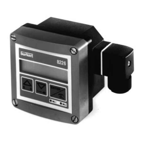
    BEDIENUNG MENÜFÜHRUNG Die unten abgebildete Menüführung hilft Ihnen dabei, einen gewünsch ten Parameter schnell und einfach zu finden und den Leitfähigkeitstrans mitter 8226 zu programmieren. Kennzeichnet blinkende Anzeigen. Hauptmenü ENTER 12.6 mS 0..9 0..9 20.6 °c ENTER 0..9 10.32 KALIBRIERMENÜ...
  • Seite 105: Hauptmenü

    Werden die Relais in ihrem vorherigen Zustand belassen. Wird der Zugriff auf die alternativen Menüs verweigert. Blinken die Parameter im Hauptmenü. HALTEN ENTER HALT N ENTER 0..9 12.6 mS HALT JA ENTER 20.6 C 0..9 10.32 mA HALTEN ENTER 12.6 mS 8226...
  • Seite 106: Kalibriermenü

    Auswahl der Meßwertglättung. Es stehen 4.4.7 FILTER zehn verschiedene Stufen zur Auswahl. (0 bis 9) Zurück zum Bedienungsmodus (Hauptmenü); speichert die ENDE neuen Parametereinstellungen. In den folgenden Abschnitten wird erklärt, wie die Parameterwerte im oben dargestellten Kalibriermenü geändert werden. 8226...
  • Seite 107: Sprache

    Die Auswahl von Einheiten wird durch die Enter-Taste bestätigt und gilt sofort im gesamten Menüführungssystem. Die Leitfähigkeit kann mit 0, 1, 2 oder 3 Dezimalstellen angegeben wer den; es werden jedoch immer 4 Ziffern angezeigt. (µSiemens/cm wird stets in Ganzzahlen ausgedrückt; Siemens/cm stets mit 3 Dezimalstellen). 8226...
  • Seite 108: Sensorkoeffi Zient

    = 0,985 (DN 50 in Messing) = 6,295 x 0,985 = 6,200 K=06.000 SENS.KOEF ENTER 0..9 K=06.200 T° KOEFF ENTER Korrekturfaktor-Tabelle für den Transmitter 8226 ß Überwurfmutter mit Klebe-oder Schwei enden Anschlüsse mit ß ß Schwei muffen en- und Innengewinde...
  • Seite 109: Änderung Der Zellkonstanten

    - Alter Wert des Sensorkoeffizienten, Leitf Bezug - Mit Bezugsgerät gemessene Leitfähigkeit, Leitf 8226 - Mit Transmitter 8226 gemessene Leitfähigkeit, alter Wert des Sensorkoeffizienten. Kalibrierung mit einer Lösung von 10,00 mS Programmierte elektrische Zellkonstante = 6,295 Vom 8226 gemessene Leitfähigkeit = 10,50...
  • Seite 110: Temperaturkompensationskoeffi Zient

    Produkte aus. Zu den verfügbaren Kompensationskurven gehören: NaOH, HNO NaCl oder Spezial (über Teach-In ermittelt). 3) Teach-In-Funktion (TEACH-IN) Mit dieser Funktion kann der Benutzer die Kompensationskurve für eine Flüssigkeit über dem erforderlichen Temperaturbereich ermitteln. Durch Eingabe der Temperaturgrenzwerte errechnet der Leitfähigkeitstransmitter bei Meßbeginn automatisch die Kompensationskurve. 8226...
  • Seite 111: Lineare Temperaturkompensation (Linear)

    Die lineare Kompensation gilt nur für Temperaturen > 0 °C Für die Berechnung des durchschnittlichen Kompensationswertes α kann die folgende Formel verwendet werden: α Die nachstehende Abbildung erläutert die Bedeutung der Koeffizienten für die lineare Tem- peraturkompensation. 25 C Abb. 4.1 - Lineare Kompensation 8226...
  • Seite 112: Automatische Temperaturkompensation (Auto)

    Die Option "SPECIAL“ ist erst verfügbar, wenn ein Teach-In-Vorgang abgeschlossen wurde. Die gespeicherten Koeffizienten für NaCl gelten für Konzentrationen zwischen 60mg/l (≅ 100µS) bis 270 g/l (≅ 220mS). In den meisten Fällen ist diese Kompensation für Wasser und verdünnte Lösungen ausreichend. 8226...
  • Seite 113: Teach-In-Temperaturkompensation (Teach-In)

    Die Teach-In- Option kann jederzeit verlassen werden, indem gleichzeitig 5 Sekunden lang gedrückt werden. 0..9 T° KOEFF ENTER TEACH IN T-= 000 ENTER 0..9 0..9 T-= 015 T+= 000 ENTER 0..9 T+=110 MEASURE ENTER T°= 065 STROM MEAS END ENTER 8226...
  • Seite 114 Das Ende des Meßbereichs eingeben.(20mA) 20= 00.00 0..9 RELAIS 1 ENTER 20= 12.00 2 ... 12 mS/cm entspricht 4...20 mA. Die folgende Abbildung zeigt die Art der Beziehung zwischen dem Ausgangssignal 4..20 mA und dem zugehörigen Meßbereich. Abb. 4.3 - Ausgangssignal 8226...
  • Seite 115: Relais (Option)

    1+ und 2+ = die oberen Grenzwerte für beide Relais. Kontakt nicht umgekehrt umgekehrt Verzögerung = 0 s Verzögerung = 2 s 2+ (8) 2- (6) 1+ (4) mS/cm mS/cm 1- (2) Relais 1 Relais 2 VERZ 2 S VERZ 2 S 8226...
  • Seite 116 DEL1 = 000 Die Verzögerung (in Sekunden) eingeben, die für beide Grenz- 0..9 werte von Relais 1 gilt. RELAIS 2 ENTER DEL1 = 004 Um eine Relaiskonfiguration zu deaktivieren, muß die Leitfähigkeit der Grenzwerte 1+ und 1- zu 0,00 eingestellt werden. 8226...
  • Seite 117: Relais 1

    Grenzwerte von Relais 2 INV N gelten soll. 0..9 FILTER ENTER DEL2 = 004 INV JA FILTER ENTER INV N Wenn das Relais 2 als Alarm verwendet wird, muß sichergestellt werden, daß der Endzustand des Relais einer Sicherheitsstellung des Prozesses entspricht. 8226...
  • Seite 118: Filterfunktion

    Für die meisten Anwendungen eignet sich Filter 2 mit einem mittleren Meßwertglättungsef- fekt. FILTER FILTER 0 ENTER 0..9 FILTER 9 ENDE ENTER Aus dem folgenden Diagramm ist zu ersehen, wie die verschiedenen Filter die Leitfähig- keitsausgabe beeinflussen. Filter 3 Leitfähigkeit Filter 6 Filter 9 8226...
  • Seite 119 OFFSET und SPAN. Wenn einer der beiden Werte ungeeignet ist, kehrt das Gerät automatisch zum Parameter „OFFSET“ zurück. Dann müssen neue Werte eingegeben werden. In den folgenden Abschnitten wird beschrieben, wie die Parameter im obigen Testmenü geändert und bewertet werden. 8226...
  • Seite 120: Testmenü

    Messen Sie den ausgegebenen Strom mit einem Amperemeter. Wenn der angezeigte Wert falsch ist, kann er geändert werden, indem der gemessene Wert eingegeben wird. Einstellbereich: + / - 0.5mA SPAN SP= 20.00 ENTER Den gemessenen Wert 0..9 eingeben. T° ADJUST ENTER SP= 19.96 8226...
  • Seite 121: Temperatureinstellung

    TESTMENÜ 4.5.3 Temperatureinstellung Der Leitfähigkeitstransmitter 8226 verfügt über einen Temperaturfühler im Sensor. Tempe- raturänderungen führen zu Änderungen der gemessenen Leitfähigkeit, die man mit enem als Offset bezeichneten Korrekturwert beeinflüssen kann. Um einen gewünschten Offset ein- zugeben, drücken Sie , wenn „T ADJUST“ im Testmenü angezeigt wird, und geben ENTER den Wert ein.
  • Seite 122: Leitfähigkeitssimulation

    Um das Gerät zu kalibrieren, wird der Sensor in die Luft gehalten und „KALIB YES“ gewählt. Das Gerät führt dann automatisch einen Kalibrierungstest durch. ENTER KALIB NO ENTER KALIB KALIB YES ENTER KALIB 1 Der Vorgang der Kalibrierung dauert etwa 1 Minute. 8226...
  • Seite 123: Einstellungen Des 8226

    INFORMATIONEN EINSTELLUNGEN DES 8226 Der Leitfähigkeitstransmitter 8226 wird werksseitig vor der Auslieferung auf die in der fol- genden Tabelle aufgeführten Werte eingestellt. 4.6.1 Werkseinstellungen für den Leitfähigkeitstransmitter 8226 Sprache: Englisch Leitfähigkeitseinheit: mS/cm Temperatureinheit: °C Relais: 00,00 Dezimalstellen: ≅ 6,30 (PVDF)
  • Seite 124: Wartung

    Fehler bei jeder Bestätigung des Menüs? Gerät zurückschicken Anzeige im Teach-In-Modus? Teach-In neu ausführen 4.4.4.3 Anzeige’ ---- °C’ Temperatur der Flüssigkeit zwischen -40 und 120 Nein ---- Gerät außerhalb des Wertebe- °C? reichs Schwarzes Verbindungskabel angeschlossen Schwarzes Verbindungskabel Nein (Transmitter öffnen?) erneut anschließen 8226...
  • Seite 125 Leitfähigkeit oder Temperatur außerhalb des Grenzwertbereichs? Nein 3.3.3 Relais korrekt angeschlossen? Relais anschließen 3.3.3 Relais richtig anschließen Anschluß der Relais 1 und 2 vertauscht? Nein Sicherungen auswechseln Schutzsicherungen für die Relais OK? Nein ---- Relaisschalter auf ‘ON’ Relaisschalter auf ON? 8226...
  • Seite 126: Technische Daten

    Software: Offset (4mA) und Span (20mA) einstellbar Relaisausgang Relaisart Normal offen Schaltleistung DC: 250V = ; 3A AC: 250V ≅ ; 3A - Lebensdauer 100 000 Schaltungen (Minimum) Grenzwerte Hysterese frei einstellbar für Leitfähigkeit oder Temperatur Verzögerung Einstellbar von 0...180 s 8226...
  • Seite 127: Abmessungen

    Konformität zu Standards Strahlung laut Norm EN 50081.1 Immunität laut Norm EN 50082.2 Ausgangsstromgenauigkeit +/- 2% laut Test ENV 50145 (nur für 115/230VAC Version mit Relais) Sicherheit laut Sicherheitsregelungen für Meßinstrumente für die Regel- und Labortechnik NF EN 61010-1 8226...
  • Seite 128 126 (4,96") 126 (4,96") 2508-Stecker: DIN43650 mit Kabel- Kabelverschraubung verschraubung 88 (3,46") 88 (3,46") 106 (4,06") 126 (4,96") 2509-Stecker: DIN43650 ohne Ka- Reduktion NPT 1/2 ‚‘ belverschraubung, mit Reduktion NPT 1/2 ‚‘ 88 (3,46") 88 (3,46") Variable Abmessungen (in mm) 8226...
  • Seite 129: Meßverfahren

    Das induzierte Magnetfeld erzeugt einen Strom in der Sekundärspule. Die Stromstärke ist der elektrolytischen Leitfähigeit der Lösung zwischen den beiden Magnetspulen direkt proportional. LEITFÄHIGE FLÜSSIGKEIT TYPENANGABE Induktiver Leitfähigkeitstransmitter 8226 Sensor aux PVDF und Gehäuse aus PC Spannungs- Ausgänge Dichtungs- Anschluß...
  • Seite 130: Anhang

    ANHANG TYPENSCHILD 8226 Leitfähigkeit Typ des Transmitters Dichtungsmaterial Sensormaterial Seriennummer Relais-Kenngrößen COND :8226-FPM-PVDF 0047 12-30 V = 250 mA 4-20 mA REL :48 VAC ; 75 VDC/3A Ausgangsstrom Betriebsspannung 431679 Stromverbrauch W4YUP Werkinterne Nr. Schutzklasse CE-Zeichen Bestell-Nr. ERSATZTEILLISTE Position Benennung Bestell-Nr.
  • Seite 131 PPA-Sensorgehäuse für 2 Kabelverschraubungen + 552399 Ring + Überwurffmutter Ring 619205 PC-Überwurfmutter 619204 PPA-Überwurfmutter 440229 Satz mit 1 grünen FPM-Dichtung + 1 schwarzen EPDM- Dichtung (für den Sensor) 552111 Induktiver Leitfähigkeitssensor mit PVDF-Sensor 427139 440230 Induktiver Leitfähigkeitssensor mit PEEK-Sensor NPT 1/2 8226...
  • Seite 132 ANHANG 8226 Pneutrol International Limited Unit 173 Argyle Industrial Estate, Argyle Street, Nechells, Birmingham B7 5TE www.pneutrolfluidcontrol.com sales@pneutrol.com Tel: +44 (0) 1213287288...

Inhaltsverzeichnis