Herunterladen Inhalt Inhalt Diese Seite drucken
bürkert 8205 Bedienungsanleitung

bürkert 8205 Bedienungsanleitung

Ph-transmitter
Vorschau ausblenden Andere Handbücher für 8205:
Inhaltsverzeichnis

Werbung

Verfügbare Sprachen

Verfügbare Sprachen

BEDIENUNGSANLEITUNG pH-TRANSMITTER 8205 .................................................. D-1
INSTRUCTION MANUAL pH TRANSMITTER 8205 ........................................................E-1
MANUEL D'UTILISATION TANSMETTEUR DE pH 8205 ................................................F-1
© BÜRKERT 2005
00555697 - Jul05 - Ind_E
Technische Änderungen vorbehalten
We reserve the right to make technical changes without notice
Sous réserve de modifications techniques

Werbung

Inhaltsverzeichnis
loading

Inhaltszusammenfassung für bürkert 8205

  • Seite 1 BEDIENUNGSANLEITUNG pH-TRANSMITTER 8205 ..........D-1 INSTRUCTION MANUAL pH TRANSMITTER 8205 ............E-1 MANUEL D'UTILISATION TANSMETTEUR DE pH 8205 ..........F-1 © BÜRKERT 2005 00555697 - Jul05 - Ind_E Technische Änderungen vorbehalten We reserve the right to make technical changes without notice Sous réserve de modifications techniques...
  • Seite 2: Inhaltsverzeichnis

    Temperaturausgleich ......................D-34 4.4.4 pH-Simulation .......................... D-34 WARTUNG ............................D-35 5.1 Austausch der Elektrode (kompakte Ausführung) ................D-35 5.2 Reinigung der Elektrode ........................D-35 5.3 Fehler-Meldungen ..........................D-36 5.4 Werk-Einstellungen des 8205 bei Auslieferung ................D-36 5.5 Ersatzteil-Stückliste..........................D-37 D-2-...
  • Seite 3: Ph-Wert Transmitter 8205

    1 EINFÜHRUNG PH-WERT TRANSMITTER 8205 Sehr geehrter Kunde, Vor dem Einbau oder der Inbetriebnahme 1.3 Sicherheitshinweise dieses Gerätes beachten Sie bitte unsere Anwendungsberatung, durch sorgfältiges Bürkert stellt eine breite Palette an pH- Lesen dieser Betriebsanleitung. Transmittern her (Kompakt, Wandmontage- oder Schrankmontage-Ausführung). Jeder AUF DIESE WEISE KÖNNEN SIE ALLE...
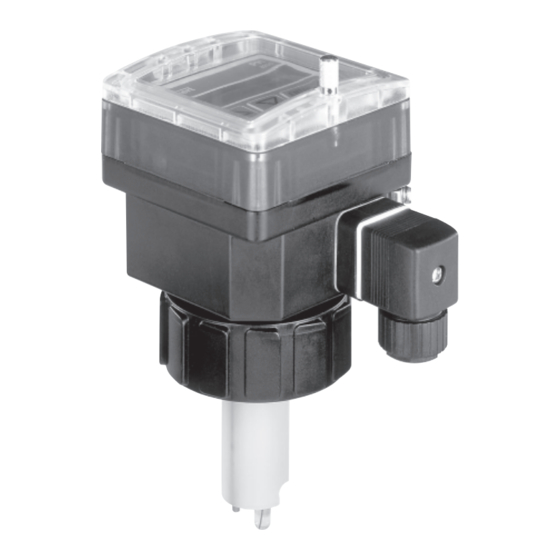
  • Seite 4: Beschreibung

    Der Lieferumfang enthält 1 Kit mit einer schwarzen EPDM-Dichtung für den Sensor, einem Verschluss für Kabelverschraubung M20x1.5, einer Mehrwegdichtung 2x6 mm für Kabelverschraubung und einem Montageblatt. 2.2 Ausführungen des pH-Wert Transmitters 8205, getrennte Ausf. Minimaler Abstand: 5 m 8205 Schaltschrank-Ausführung...
  • Seite 5: Abmessungen

    Spannungs-versorgung von 12-30 VDC (115/230 VAC in Wandmontage- Ausführung). Ein 4-20 mA Standard-Ausgangs-Signal, proportional zum pH-Wert (oder T°C), ist verfüg- bar. 2.4 Abmessungen pH-Wert Transmitter 8205 Fig 2.1 Abmessungen 8205 Transmitter als Schaltschrank-Ausführung (ohne Sensor) und Ausschneid-Schablone D-5-...
  • Seite 6 PH-WERT TRANSMITTER 8205 2 BESCHREIBUNG H (mm) DN (mm) T-fitting Anschluss- Kunststoff- Edelstahl- schellen stutzen stutzen Fig. 2.2 Abmessungen des pH-Wert Transmitters 8205, kompakte Ausführung D-6-...
  • Seite 7: Technische Daten

    2 BESCHREIBUNG PH-WERT TRANSMITTER 8205 Überdeckungs-Blende Überdeckungs-Blende ø 19 5 Kabelverschraubungen + 1 Reduziereinsatz Fig 2.3 Abmessungen Transmitter 8205 Wandmontage-Ausführung 2.5 Technische Daten Messung des pH-Werts Messbereich 0...14 pH Messfeinheit 0,01 pH Genauigkeit ± 0,02 pH, nach Kalibrierung der Elektrode...
  • Seite 8 2 BESCHREIBUNG PH-WERT TRANSMITTER 8205 Min. Abstand des PH-Bereichs, das dem 4-20 mA-Signal entspricht 0,5 pH (z.B.: Bereich 50 bis 100 mV entspricht dem 4-20 mA-Ausgangsstrom) Schutzart IP 65 (Kompakt und Wandmontage-Ausführungen und Deckel der Schaltschrank-Ausführung) IP 20 (Rückseite der Schaltschrank-Ausführung)
  • Seite 9: Installation

    Hand festgezogen werden! Temperatur (°C) Einbauvorschriften Setzen Sie den PH-Transmitter in vertikaler Position in ein Horizontalrohr ein. 75° 75° Das Gerät muss vor dem Regen, vor Ultraviolettbestrahlung und elektromagnetischen Störungen geschützt werden. Fig. 3.1 Montage 8205, kompakte Ausfüh- rung D-9-...
  • Seite 10 4 Bolzen an die Schaltschrankwandung. 5. Schließen Sie den Transmitter gemäß § 3.2 an. 6. Mittels den 4 mitgelieferten Kabelschellen die Kabel an die Schutzplatte befestigen. Schraube Scheibe Bolzen Dichtung Kabelschelle Fig 3.2 Installation pH-Transmitter 8205, Schaltschrank-Ausführung D-10-...
  • Seite 11: Transmitter 8205 Wandmontage-Ausführung

    Auswahl Versorgungs- Sicherung spannung 115/230 VAC 1 2 3 4 5 6 7 8 9 10 Fig 3.3 Installation pH-Transmitter 8205 Wandmontage-Ausführung 3.2 Elektrischer Anschluss 3.2.1 Allgemeine Hinweise zum elektrischen Anschluss Der Transmitter darf nicht bei angeschlossenem Netzkabel geöffnet werden.
  • Seite 12 PH-WERT TRANSMITTER 8205 3 INSTALLATION Vergewissern Sie die Äquipotentialität der Installation (Stromversorgung - Transmitter - Flüssigkeit): - Die verschiedene Erdungspunkte der Installation müssen aneinander angeschlossen sein, damit die zwischen zwei Erdungspunkten möglicherweise erzeugten Potential differenzen beseitigt werden. - Es muss auf vorschriftsmäßige Erdung der Abschirmung geachtet werden.
  • Seite 13: Elektrischer Anschluss Kompakt-Ausführung Mit En 175301-803-Stecker

    PH-WERT TRANSMITTER 8205 3 INSTALLATION Getrennte Ausführungen, Prinzip einer Äquipotentialität: 8205 Wandmontage- oder Schaltschrank- Versorgung Ausführung 8200 Geräte wie Ventil, Kunststoffrohre Pumpe, usw... 8205 Wandmontage- oder Schaltschrank- Versorgung Ausführung 8200 Metallische Rohre (*) ist keine direkte Erdung möglich, schließen Sie einen 100 nF/50V-Kondensator zwischen dem negativen Anschluss der Versorgungsquelle und der Erde an.
  • Seite 14: Einsatz Der Kabelschellen

    Verkabelung des EN 175301-803-Steckers Abschirmung des Versorgungskabels verbinden (12-30 VDC) Nicht belegt L- (0 VDC) Anschluss des Transmitters 8205 mit EN175301-803-Stecker an eine SPS: 250 mA 4-20 mA 4-20 mA 250 mA 1 2 3 4 1 2 3 4...
  • Seite 15: Elektrischer Anschluss Kompakt-Ausführung Ohne Relais, Mit Kabelveschraubungen

    Abschirmung des Versorgungskabels verbinden 1 2 3 4 Anschluss des pH-Sensors Anschluss des Temperatur-Sensors (je nach Version) Fig. 3.6 Anschluss des Kompakt 8205, ohne Relais, mit Kabelverschraubungen Anschluss des pH-Transmitters an eine SPS: 250 mA 4-20 mA 250 mA 4-20 mA...
  • Seite 16: Elektrischer Anschluss Kompakt-Ausführung Mit Relais, Mit Kabelveschraubungen

    Relais-Kabel müssen mittels mitgelieferten Kabel- schellen an die Platine befestigt werden (siehe § 3.2.3) Fig. 3.8 Anschluss 8205 Kompakt, mit Relais, mit Kabelverschraubungen Anschluss des 4-20 mA-Ausgangs des pH-Transmitters 8205 an eine SPS und Anschluss- beispiel für die Relais, siehe Fig. 3.9. D-16-...
  • Seite 17 3 INSTALLATION PH-WERT TRANSMITTER 8205 Anschluss des 4-20 mA-Ausgangs des pH-Transmitters 8205 an eine SPS. Der SPS-Aus- führung entsprechend muss der Quelle/Senke-Schalter korrekt eingestellt werden (siehe Fig. 3.8). Schalter nicht unter Spannung einstellen! 250 mA 4-20 mA 4-20 mA 250 mA...
  • Seite 18: Elektrischer Anschluss Schaltschrank-Ausführung Ohne Relais

    3 : weißer Draht 4 : grün/gelber Draht Pt1000 PE : Abschirmung des Kabels Mediums-Äquipotentialität Fig. 3.10 Anschluss des Transmitters, Schaltschrank-Ausführung, ohne Relais Anschluss des 4-20 mA-Ausgangs des pH-Transmitters 8205 an eine SPS: 250 mA 4-20 mA 250 mA 4-20 mA CURRENT CURRENT...
  • Seite 19: Elektrischer Anschluss Schaltschrank-Ausführung Mit Relais

    Mediums-Äquipotentialität den (siehe § 3.2.3) Fig. 3.12 Anschluss des Transmitters, Schaltschrank-Ausführung, mit Relais Anschluss des 4-20 mA-Ausgangs des pH-Transmitters 8205 an eine SPS. Der SPS-Aus- führung entsprechend muss der Quelle/Senke-Schalter korrekt eingestellt werden (siehe Fig. 3.12). Schalter nicht unter Spannung einstellen!
  • Seite 20: Elektrischer Anschluss Wandmontage-Ausführung, 12-30 Vdc, Ohne Relais

    12-30 VDC oder 115/230 VAC Fig. 3.14 Zuordnung der Kabelverschraubungen, Wandmontage-Ausführung Schließen Sie die Kabel folgendermaßen an. Anschluss des pH-Transmitters 8205, Wandmontage-Ausführung, ohne Relais, an eine SPS erfolgt wie eine Schaltschrank-Ausführung, ohne Relais (siehe Fig. 3.11). L+ (12-30 VDC) Abschirmung des...
  • Seite 21: Elektrischer Anschluss Wandmontage-Ausführung, 12-30 Vdc, Mit Relais

    Deckel öffnen. Kabelverschraubungen aufschrauben. Folgen Sie bitte die in Fig. 3.14 angegebenen Zuordnung der Verschraubungen. Anschließend Kabel laut folgende Anschlusspläne anklemmen. Anschluss des pH-Transmitters 8205, Wandmontage-Ausführung, mit Relais, an eine SPS erfolgt wie eine Schaltschrank-Ausführung, mit Relais (siehe Fig. 3.13). Schalter nicht unter Spannung einstellen! "Stromausgangsmodus"-Schalter...
  • Seite 22 3 INSTALLATION PH-WERT TRANSMITTER 8205 3.2.10 Elektrischer Anschluss Wandmontage-Ausführung, 115/230 VAC, ohne Relais Bauen Sie den Transmitter gemäß Einbauvorschriften des § 3.1.3 an. Die 4 Schrauben lösen und den Deckel öffnen. Kabelverschraubungen aufschrauben. Folgen Sie bitte die in Fig. 3.14 angegebenen Zuordnung der Verschraubungen. Anschließend Kabel laut folgende Anschlusspläne anklemmen.
  • Seite 23 3 INSTALLATION PH-WERT TRANSMITTER 8205 3.2.11 Elektrischer Anschluss Wandmontage-Ausführung, 115/230 VAC, mit Relais Bauen Sie den Transmitter gemäß Einbauvorschriften des § 3.1.3 an. Die 4 Schrauben lösen und den Deckel öffnen. Kabelverschraubungen aufschrauben. Folgen Sie bitte die in Fig. 3.14 angegebenen Zuordnung der Verschraubungen. Anschließend Kabel laut folgende Anschlusspläne anklemmen.
  • Seite 24: Bedienung

    PH-WERT TRANSMITTER 8205 4 BEDIENUNG Die Bedienung des Transmitters ist in 3 Bereiche unterteilt. 1. Anzeige pH-Wert, Temperatur und Ausgangsstrom werden im normalen Funktionsmodus angezeigt. Die HALTEN- Funktion und die Elektroden-Kalibrier-Funktion (pH KALIB) sind von diesem Menü aus zugänglich. 2. Kalibrieren Im Kalibriermodus sind folgende Einstellungen möglich: Auswahl von Sprache, Einheiten...
  • Seite 25: Anzeige Des Bedienungs-Modus

    PH-WERT TRANSMITTER 8205 4 BEDIENUNG 4.2 Anzeige des Bedienungs-Modus Die folgenden Verfahrenswerte werden im Bedienungs-Modus angezeigt. ph = 12.60 pH-Wert mit zwei Dezimalstellen (§ 4.2.2) 20.6 °c Temperatur in °C oder °F (§ 4..3.2) 10.32 Ausgangssignal 4-20 mA, proportional zum pH-Wert bzw.
  • Seite 26: Kalibrierung Der Ph-Elektrode

    4 BEDIENUNG PH-WERT TRANSMITTER 8205 4.2.2 Kalibrierung der pH-Elektrode Der Benutzer verfügt über 2 Kalibrierverfahren: mit 1 oder 2 Messpunkten. Verfahren mit 1 Messpunkt: ermöglicht die schnelle Transmitter-Kalibrierung mit Hilfe einer Pufferlösung mit pH-Wert = 7. Verfahren mit 2 Messpunkten: ermöglicht eine präzise Kalibrierung von Nullpunkt und spezi- fischer Kurve der pH-Elektrode.
  • Seite 27 4 BEDIENUNG PH-WERT TRANSMITTER 8205 PH =7.00 1 PUNKT ph kalib ENTER ENTER Elektrode in Lösung Entertaste während 5 ENTER eintauchen und bestätigen Sek. drücken kalib... Automatische Bestätigung ENTER (ca. 20 Sek.) oder Druck auf Entertaste OF = -5.1 ph = 9.25...
  • Seite 28: Parametriermenü

    4 BEDIENUNG PH-WERT TRANSMITTER 8205 ENTER 4.3 Parametriermenü: gleichzeitig während 5 Sekunden drücken Im Parametriermenü können folgende Einstellungen vorgenommen werden: SPRACHE Sprachauswahl: deutsch, englisch, französisch, italienisch oder spanisch (§ 4.3.1) EINHEIT Auswahl der Temperatureinheit (§ 4.3.2) STROM Festlegung des 4-20 mA Messbereiches (§ 4.3.3) RELAIS 1 Parametrierung des Relais 1 (pH oder T°C) (*) (§...
  • Seite 29: Temperatureinheiten

    4 BEDIENUNG PH-WERT TRANSMITTER 8205 4.3.2 Temperatureinheiten Die Temperatur kann in °Celsius oder in °Fahrenheit angezeigt werden. T°EINHEIT ENTER °CELSIUS °FAHRENH STROM ENTER 4.3.3 Ausgangsstrom Einheit des Wertes wählen (pH- oder Temperatur) und Messbereich entsprechend der Ausgangsleistung zwischen 4 und 20 mA eingeben. Zum Beispiel kann ein pH-Wert von 2 bis 12 einem Strom von 4 bis 20 mA entsprechen.
  • Seite 30: Relais

    4 BEDIENUNG PH-WERT TRANSMITTER 8205 4.3.4 Relais Relais 1: Die Messung auswählen (pH oder Temperatur) und die 2 Grenzwerte 1- und 1+ eingeben. Es gibt die Möglichkeit die Relais zu invertieren (NO/NC) und eine Verzögerungzeit zwi- schen 0 und 999 Sekunden einzustellen.
  • Seite 31 4 BEDIENUNG PH-WERT TRANSMITTER 8205 Relais 1 ENTER RELAIS 1 PH ALARM ENTER °c ALARM 1-=00.00 0..9 1+=06.50 ENTER Hinweis : 1- ≤1+ und 1+=00.00 ∆ pH> 0,2 (oder ∆ T° > 2°C) 0..9 1+=07.50 ENTER INV NEIN DEL.=000 INV JA ENTER 0..9...
  • Seite 32: Auswahl Des Temperaturkompensations-Modus

    4 BEDIENUNG PH-WERT TRANSMITTER 8205 4.3.5 Auswahl des Temperatur-Kompensations-Modus Wenn der Pt1000 nicht benutzt wird, FUHLER N wählen und den Temperaturwert des Mediums eingeben. FUHLER n FUHLER T° + 023 ENTER ENTER FUHLER J 0..9 + 045 U ELEKTR ENTER U ELEKTR 4.3.6 Anzeige der Elektroden-Spannung...
  • Seite 33: Testmenü

    4 BEDIENUNG PH-WERT TRANSMITTER 8205 ENTER 4.4 Testmenü: gleichzeitig während 5 Sekunden drücken 0..9 Im Testmenü werden folgende Abgleiche und Überprüfungen durchgeführt: OFFSET Grundeinstellung: Abgleich des Offsets (4 mA). SPAN Grundeinstellung: Abgleich der Spanne (20 mA). T° EINSTE Temperatur-Wert Korrektur. Die Ausgänge reagieren entspre- 0..9...
  • Seite 34: Temperaturausgleich

    4 BEDIENUNG PH-WERT TRANSMITTER 8205 4.4.3 Temperaturausgleich Der vom Pt1000 gelieferte Temperaturwert kann korrigiert werden. Geben Sie den ge- forderten Temperaturausgleichswert (innerhalb des Temperaturbereichs ± 5°C) ein und bestätigen Sie diesen anschliessend. Die Temperatureinheit ist die gleiche, wie im vorherge- henden Grundeinstellungsmenü...
  • Seite 35: Wartung

    5 WARTUNG PH-WERT TRANSMITTER 8205 5.1 Austausch der Elektrode (kompakte Ausführung) pH-Elektroden haben eine begrenzte Lebensdauer, die von mehreren Parametern abhängt, wie z.B. der chemischen Zusammensetzung der umgebenden Flüssigkeit, der Temperatur, dem Druck, usw. Für die Elektrode wird keine Garantie des Herstellers gewähleistet.
  • Seite 36: Fehler-Meldungen

    Elektrodenspannung: > + 575 mV oder < - 575 mV. "PH=---" und "---mV" werden ange- zeigt. Für die Ausgänge (Strom und Relais) wird pH = 0 bzw. pH = 14 festgelegt. 5.4 Werk-Voreinstellungen des Transmitters 8205 bei Lieferung Sprache: Englisch...
  • Seite 37: Ersatzteil-Stückliste

    PH-WERT TRANSMITTER 8205 5 WARTUNG 5.5 Ersatzteil-Stückliste 5.5.1 pH-Wert-Transmitter 8205, kompakte Ausführung Bestell- Position Bezeichnung Deckel mit Klappe, Fenster, Folie und Schrauben 553189 Leiterplatte mit Relais 555719 Leiterplatte ohne Relais 555718 Stecker EN 175301-803 mit Kabelverschraubung (Typ 2508) 438811 Stecker EN 175301-803 mit NPT 1/2''-Reduktion (Typ 2509)
  • Seite 38 5 WARTUNG PH-WERT TRANSMITTER 8205 NPT 1/2 Fig. 5.1 Ersatzteile für pH-Wert Transmitter 8205, kompakte Ausführung 205 ml Pufferlösung pH=4, 500 ml 418540 205 ml Pufferlösung pH=7, 500 ml 418541 205 ml Pufferlösung pH=10, 500 ml 418543 Aufbewahrungslösung für pH-Elektroden (KCl 3M), 250 ml...
  • Seite 39: Ersatzteil-Stückliste Ph-Wert-Transmitter 8205 Schaltschrank-Ausführung

    Leiterplatte mit Relais + Schutzplatten + Montageblatt 555721 Satz Montage-Zubehör (Bolzen, Schrauben, Fächerschei- 554807 ben, Kabelschellen) Flachdichtung 419350 Satz mit 8 "pH" Folie, ohne "Relais"-Markierung 553197 Satz mit 8 "pH" Folie, mit "Relais"-Markierung 553198 Fig 5.2 Ersatzteile für pH-Wert-Transmitter 8205 Schaltschrank-Ausführung D-39-...
  • Seite 40: Ersatzteil-Stückliste Ph-Wert-Transmitter 8205 Wandmontage-Ausführung

    5.5.3 Ersatzteil-Stückliste pH-Wert-Transmitter 8205 Wandmontage-Ausführung Position Bezeichnung Bestell-Nr Komplettes Gehäuse IP65 427096 Leiterplatte ohne Relais + Schutzplatten + Montageblatt 555720 Leiterplatte mit Relais + Schutzplatten + Montageblatt 555721 Platine Spannungsversorgung 115/230 VAC 555722 Fig 5.3 Ersatzteile für pH-Wert-Transmitter 8205 Wandmontage-Ausführung D-40-...
  • Seite 41 Temperature-Compensation Coefficient .................E-33 4.4.4 pH-Simulation ........................E-33 MAINTENANCE ..............................E-34 Replacement of the pH electrode ....................E-34 Storing and Cleaning of the Electrode ....................E-34 5.3 Error messages ............................E-35 Factory-settings of 8205 Transmitter at delivery ................E-35 Spare parts ............................E-36 E-1- Réf. 555697 - Jul05 - Ind_E...
  • Seite 42: Introduction

    1 INTRODUCTION PH TRANSMITTER 8205 Dear Customer, BEFORE INSTALLING OR USING THIS 1.3 User's Responsibility for Safety PRODUCT, PLEASE TAKE OUR AD- VICE AND READ THE ENTIRE MANUAL Bürkert manufactures a broad range of pH THOROUGHLY. transmitters (compact, wall-mounted or pa- nel versions).
  • Seite 43: Specification

    427949 4-20 mA, 2 relays 115/230 VAC 427950 The pH sensor holder 8200 for a short distance pH-transmitter 8205 must be ordered separately: see corresponding datasheet or instruction manual (order code 428937). 2.3 Design and Measuring Principle Design pH transmitter 8205 compact The pH-transmitter compactly combines a pH-sensor and a transmitter with display.
  • Seite 44: Dimensions

    PH TRANSMITTER 8205 pH transmitter 8205, separate, connection distance < 10 m The separate 8205 transmitter, short distance, must be connected to a pH-sensor holder 8200 (Instruction manual ref. 428937) made up of an holder, a pH-electrode and usually a Pt1000 temperature sensor.
  • Seite 45 2 SPECIFICATION PH TRANSMITTER 8205 H (mm) DN (mm) T-fitting Saddle Plastic Welding tab spigot Fig. 2.2 Dimensions pH transmitter 8205 compact version E-5-...
  • Seite 46: Technical Data

    2 SPECIFICATION PH TRANSMITTER 8205 blanking strip blanking strip ø 19 5 cable glands + 1 cable gland reducer Fig. 2.3 Dimensions pH transmitter 8205 wall-mounted version 2.5 Technical data pH measurement Measuring range 0...14 pH Resolution 0,01 pH Measuring error ±...
  • Seite 47 2 SPECIFICATION PH TRANSMITTER 8205 Min. difference of the pH measuring range corresponding to the 4-20 mA signal 0,5 pH unit (ex: range 6,7 to 7,2 pH corresponds to the 4-20 mA current output) Protection rating IP 65 (compact, wall-mounted and front panel of the...
  • Seite 48: Installation

    3 INSTALLATION PH TRANSMITTER 8205 3.1 Installation Guidelines The electrode must continuously be im- The transmitter must be calibrated with buf- mersed into the measuring fluid in order to fer solutions (see § 4.2) prior to installation. protect it from drying out.
  • Seite 49: Installing A Panel-Mounted Version

    PH TRANSMITTER 8205 3.1.2 Installing a panel-mounted version Follow the instructions below to install the 8205 into a panel: 1. Use the supplied drilling jig to cut away the necessary opening in the panel. Make sure to scrupulously respect the dimensions indicated.
  • Seite 50: Installing A Wall-Mounted Version

    230/115 VAC 1 2 3 4 5 6 7 8 9 10 Fig. 3.3 Installation pH transmitter 8205 wall-mounted version 3.2 Electrical connection 3.2.1 General electrical requirements Do not open and wire the transmitter with the power supply connected.
  • Seite 51 PH TRANSMITTER 8205 3 INSTALLATION Ensure the equipotentiality of the installation (power supply - transmitter - fluid): The various earth spots in the installation have to be connected together to eliminate the potential differences that may occur between different earthes.
  • Seite 52 3 INSTALLATION PH TRANSMITTER 8205 Realizing (principle) the equipotentiality of a compact version: 8205 Panel or wall- mounted version Power supply 8200 Plastic pipes Metallic devices (valve, pump, etc) 8205 Panel or wall- mounted version Power supply 8200 (*) If direct earthing is impossible, connect a...
  • Seite 53: How To Use The Cable Clips

    Wiring EN 175301-803 cable plug Connect here the screening of the power supply cable (12-30 VDC) Not connected L- (0 VDC) Connection of transmitter 8205 with EN175301-803 cable plug to a PLC: 250 mA 4-20 mA 250 mA 4-20 mA Connection in sourcing mode...
  • Seite 54: Wiring Of A Compact Version Without Relay, With Cable Glands

    Connect the shielding of the power supply cable 1 2 3 4 pH sensor connection Temperature sensor connection Fig. 3.6 Wiring of the 8205, compact version, without relay, with cable glands Connecting the 8205 to a PLC: 250 mA 4-20 mA 250 mA...
  • Seite 55: Wiring Of A Compact Version With Relays, With Cable Glands

    (see § 3.2.3) Fig. 3.8 Wiring of the 8205, compact version, with relays, with cable glands Connecting the 4-20 mA output of transmitter 8205 to a PLC and connection example for the relays, see fig. 3.9. E-15-...
  • Seite 56 3 INSTALLATION PH TRANSMITTER 8205 Connecting the 4-20 mA output of transmitter 8205 to a PLC. Depending on the PLC type, position the "sourcing / sinking mode" switch properly (see fig. 3.8). Only manipulate the switch when the device is not powered.
  • Seite 57: Wiring Of A Panel-Mounted Version Without Relay

    Connection in sourcing mode Connection in sinking mode (*) If direct earthing is impossible, connect a 100 nF / 50 V-condensator between the negative terminal and the earth. Fig. 3.11 Connection to a PLC, 8205 panel-mounted version, without relay E-17-...
  • Seite 58: Wiring Of A Panel-Mounted Version With Relays

    Equipotential of the medium Fig. 3.12 Wiring of the transmitter, panel-mounted version, with relays Connecting the 4-20 mA output of transmitter 8205 to a PLC. Depending on the PLC type, position the "sourcing / sinking mode" switch properly (see fig. 3.12).
  • Seite 59: Wiring Of A Wall-Mounted Version, 12-30 Vdc, Without Relay

    Fig. 3.14 Allocation of the cable glands, wall-mounted versions Connect the terminals according to the pin assignment below. Connection of transmitter 8205 in a wall-mounted version without relay to a PLC is similar to the connection of a panel-mounted version without relay (see Fig. 3.11).
  • Seite 60: Wiring Of A Wall-Mounted Version, 12-30 Vdc, With Relays

    Pass the cables through the cable glands by preferably respecting the allocation indicated in fig. 3.14. Connect according to pin assignment below. Connection of transmitter 8205 in a wall-mounted version with relays to a PLC is similar to the connection of a panel-mounted version with relays (see Fig. 3.13).
  • Seite 61: Wiring Of A Wall-Mounted Version, 115/230 Vac, Without Relay

    3 INSTALLATION PH TRANSMITTER 8205 3.2.10 Wiring of a wall-mounted version, 115/230 VAC, without relay Install the transmitter as described in § 3.1.3. Unscrew the 4 screws of the cover and uns- crew the cable glands. Pass the cables through the cable glands by preferably respecting the allocation indicated in fig.
  • Seite 62: Wiring Of A Wall-Mounted Version, 115/230 Vac, With Relays

    PH TRANSMITTER 8205 3 INSTALLATION 3.2.11 Wiring of a wall-mounted version, 115/230 VAC, with relays Install the transmitter as described in § 3.1.3. Unscrew the 4 screws of the cover and uns- crew the cable glands. Pass the cables through the cable glands by preferably respecting the allocation indicated in fig.
  • Seite 63: Operation

    4 OPERATION PH TRANSMITTER 8205 The operation of the pH transmitter is classified according to 3 levels. Main Menu pH, temperature and output current are displayed in the normal function mode. The "HOLD" function and electrode calibration ("PH CALIB") can be accessed . (§ 4.2)
  • Seite 64: Operation Mode Display

    4 OPERATION PH TRANSMITTER 8205 4.2 Operation Mode Display The following process values are displayed in the display operation mode. PH = 12.60 pH value display with two decimals. 20.6 °C Temperature in °C or °F. Output signal 4...20 mA, proportional to the pH or temperature 10.32 mA...
  • Seite 65: Calibration Of Ph Electrode

    4 OPERATION PH TRANSMITTER 8205 4.2.2 Calibration of pH electrode In order to obatain reliable measurements, it is necessary to perform regular clibrations of the pH electrode. 1 or 2 measuring point calibration methods are available. 1 measuring point method: enables a quick control calibration with pH=7 buffer soluti- 2 measuring points method: enables a precise calibration of zero and slope of the pH electrode.
  • Seite 66 PH TRANSMITTER 8205 4 OPERATION PH CALIB 1 POINT PH = 7.00 ENTER ENTER Immerse electrode in Press Enter for 5 sec. ENTER the buffer solution then confirm. CALIB . . . ENTER Automatic confirmation (approx. 20 s.) or press ENTER PH = 9.25...
  • Seite 67: Calibration Mode

    4 OPERATION PH TRANSMITTER 8205 ENTER 4.3 Calibration Mode: Press simultaneously for 5 seconds The following adjustments are set in the calibration mode display: LANGUAGE English, German, French, Italian, or Spanish choice (§ 4.3.1) T° UNIT Temperature unit selection (°C; °F). (§ 4.3.2) CURRENT Adjustment of the 4...20 mA measuring range (pH or T°).
  • Seite 68: Temperature Units

    4 OPERATION PH TRANSMITTER 8205 4.3.2 Temperature units The temperature can be displayed in °Celsius or in °Fahrenheit. °CELSIUS ENTER T° UNIT °FAHRENH CURRENT ENTER 4.3.3 Output Current Enter the measuring range corresponding to the 4...20 mA output. First select the unit pH or T°current then, enter the limit values .
  • Seite 69: Configuration

    PH TRANSMITTER 8205 4 CONFIGURATION 4.3.4 Relays threshold selection Relay 1: Select the entry to be controled (pH or temperature). Enter both thresholds of the selected relay 1- and 1+. Options to invert the relay (NO/NC, and set a delay between 0 and 999 seconds are avai- lable.
  • Seite 70 4 CONFIGURATION PH TRANSMITTER 8205 Relay 1 PH ALARM ENTER RELAY 1 ENTER °C ALARM 1-=00.00 0..9 1-=06.50 Condition!: 1- ≤1+ ENTER 1+=00.00 and ∆ pH > 0,2 (or ∆ T° > 2°C) . 0..9 1+=07.50 ENTER INV NO INV YES DEL.=000...
  • Seite 71: Temperature-Compensation Mode

    4 OPERATION PH TRANSMITTER 8205 4.3.5 Temperature Compensation Mode If the Pt1000 is not used for temperature measurement, select SENSOR NO and enter the temperature value of the fluid. + 023 SENSOR T° ENTER ENTER 0..9 + 045 FILTER ENTER FILTER 4.3.6 Display of electrode voltage...
  • Seite 72: Test Menu

    4 OPERATION PH TRANSMITTER 8205 ENTER 4.4 Test Menu: Press simultaneously for 5 seconds 0..9 The following compensations and controls are carried out in the Test menu: Zero point compensation (4 mA) (§ 4.4.1) OFFSET Span compensation (20 mA) (§ 4.4.2) SPAN Temperature value correction.
  • Seite 73: Temperature Adjustment

    4 OPERATION PH TRANSMITTER 8205 4.4.3 Temperature adjustment The temperature value measured by the Pt1000 can be corrected. Enter the required offset of temperature (within the limit ± 5°C), then validate. The temperature unit is as selected in previous parameter menu. The selected temperature value influences the computed pH value.
  • Seite 74: Maintenance

    PH TRANSMITTER 8205 5 MAINTENANCE 5.1 Replacement of the pH electrode pH-electrodes are consumables and have thus a limited service life, de- pending upon many parameters, such as the chemical composition of the handled fluid, temperature, pressure, etc. The manufacturer's warranty does not cover the pH electrodes.
  • Seite 75: Error Messages

    Power failure: In case of power failure, the display turns off, 4-20 mA and pulse output to 0, alarm relays open. When the power supply is turned on, the transmitter is set to the pre- vious configuration and to operation resumes. 5.4 Factory-setting of pH transmitter 8205 at delivery Relay 2: Type pH...
  • Seite 76: Spare Parts

    5 MAINTENANCE PH TRANSMITTER 8205 5.5 Spare Parts List Transmitter 8205 5.5.1 Spare Parts List Transmitter 8205 compact Position Specification Order code Cover with lid, window and screws 553189 Electronic board with relays 555719 Electronic board without relay 555718 Cable plug EN 175301-803 with cable gland (type 2508)
  • Seite 77 5 MAINTENANCE PH TRANSMITTER 8205 NPT 1/2 Fig 5.1 Spare parts explosion drawing 8205 compact version Buffer solution pH=4, 500 ml 418540 Buffer solution pH=7, 500 ml 418541 Buffer solution pH=10, 500 ml 418543 Storage solution for electrodes (KCl 3M), 250 ml...
  • Seite 78 Mounting set (screws, washers, nuts, cable clips) 554807 Gasket 419350 Set incl. 8 "pH" folios without "relay" marking 553197 Set incl. 8 "pH" folios with "relay" marking 553198 Fig 5.2 Spare parts explosion drawing 8205 panel-mounted version E-38-...
  • Seite 79 IP65 housing 427096 Electronic board without relay + protective plates + 555720 mounting instructions Electronic board with relays + protective plates + 555721 mounting instructions 115/230 VAC power supply board 555722 Fig 5.3 Spare parts explosion drawing 8205 wall-mounted version E-39-...
  • Seite 80 PH TRANSMITTER 8205 E-40-...
  • Seite 81 Correction de température ....................F-33 4.4.4 Simulation du pH ........................F-33 MAINTENANCE ......................... F-34 Remplacement de l'électrode .......................F-34 Entretien de l'électrode ..........................F-34 Messages d'erreur ...........................F-35 Configuration des transmetteurs de pH 8205 à la livraison ............F-35 Liste des pièces de rechange ......................F-36 F-1-...
  • Seite 82: Introduction

    1 INTRODUCTION TRANSMETTEUR DE PH 8205 Pour utiliser pleinement et en toute confi- ance les fonctions de cet instrument, NOUS VOUS RECOMMANDONS DE LIRE 1.3 Consignes de sécurité ATTENTIVEMENT LA PRÉSENTE NOTICE D'EMPLOI AVANT LA MISE EN SERVICE. Bürkert commercialise une large gamme de transmetteurs de pH (versions compactes, murales ou encastrables).
  • Seite 83: Description

    427949 4-20 mA, 2 relais 115/230 VAC 427950 Armature de pH pour transmetteur de pH 8205 version séparée : voir manuel utilisateur "Armature de pH 8200" (réf 428937) 2.3 Construction et principe de mesure Construction Transmetteur de pH 8205 compact Le transmetteur de pH combine un capteur et un transmetteur digital avec affichage.
  • Seite 84 Transmetteur de pH 8205 séparé, distance de raccordement < 10 m Le transmetteur de pH 8205 séparé doit être connecté à une armature de pH 8200 (voir manuel utilisateur 428937) composée d'un support, d'une électrode de pH et en général d'une sonde de température Pt1000.
  • Seite 85 2 DESCRIPTION TRANSMETTEUR DE PH 8205 H (mm) Raccord Colliers Manchon Manchon en (mm) en T en plastique acier inoxydable Fig. 2.2 Dimensions du transmetteur de pH 8205 compact F-5-...
  • Seite 86: Caractéristiques Techniques

    TRANSMETTEUR DE PH 8205 bande de recouvrement bande de recouvrement ø 19 5 presse-étoupes + 1 réducteur de presse-étoupe Fig. 2.3 Dimensions transmetteur de pH 8205 mural 2.5 Caractéristiques techniques Mesure du pH Echelle de mesure 0...14 pH Résolution 0,01 pH Erreur de mesure ±...
  • Seite 87 2 DESCRIPTION TRANSMETTEUR DE PH 8205 Ecart min. de la plage de pH correspondant au signal 4-20 mA 0,5 unité de pH (ex: plage 6,7 à 7,2 pH correspond à la sortie courant 4-20 mA) Protection IP 65 (compact, mural et face avant version encastrable) IP 20 (face arrière version encastrable)
  • Seite 88: Installation

    Diagramme température-pression 3.1.1 Montage du 8205 compact Selon le matériau du raccord, tenir compte du rapport température/pression. Installer le transmetteur de pH 8205 sur P {bar} les conduites à l'aide de raccords spé- Zone de fonctionnement ciaux. Retirez le capuchon de protection de l'électrode et conservez-le pour stockage.
  • Seite 89 3 INSTALLATION TRANSMETTEUR DE PH 8205 3.1.2 Installation du transmetteur de pH 8205 encastrable Assembler l'appareil de la façon suivante : 1. Utiliser le gabarit fourni pour découper l'ouverture dans l'armoire. Veiller à respecter scru- puleusement les cotes indiquées. 2. Placer le joint d'étanchéité sur les 4 vis du couvercle.
  • Seite 90: Montage Transmetteur De Ph 8205 Mural

    3 INSTALLATION TRANSMETTEUR DE PH 8205 3.1.3 Montage du transmetteur de pH 8205 mural Le transmetteur de pH en version murale dispose de 4 trous de fixation dans le fond du boîtier. Retirer les bandes de recouvrement pour ouvrir le couvercle et accéder aux trous de fixation 1.
  • Seite 91 3 INSTALLATION TRANSMETTEUR DE PH 8205 Assurer l‘équipotentialité de l‘installation (alimentation - transmetteur - fluide) : raccorder les différentes terres de l’installation les unes aux autres afin de supprimer les différences de potentiel pouvant se créer entre elles. relier correctement le blindage du câble d'alimentation à la terre, aux deux extrémités.
  • Seite 92 3 INSTALLATION TRANSMETTEUR DE PH 8205 Versions déportées, schémas de principe d'une équipotentialité : 8205 Version murale ou encastrable Alimentation 8200 Appareils tels que Conduites plastiques vanne, pompe,... 8205 Alimentation Version murale ou encastrable 8200 (*) si une mise à la terre directe est impossible, Conduites métalliques...
  • Seite 93: Mise En Place Des Serre-Câbles

    TRANSMETTEUR DE PH 8205 Câblage du connecteur EN 175301-803 Raccorder le blindage du câble d'alimentation (12-30 VDC) Non connecté L- (0 VDC) Raccordement du transmetteur 8205 avec connecteur EN175301-803, à un automate : 250 mA 4-20 mA 250 mA 4-20 mA Automate Automate...
  • Seite 94 Raccordement de la sonde de pH Raccordement de la sonde de température Fig. 3.6 Connexion du 8205 compact, sans relais, avec presse-étoupes Raccordement du transmetteur de pH 8205 à un automate : 250 mA 4-20 mA 4-20 mA 250 mA...
  • Seite 95 Fixer obligatoirement les câbles relais à l'aide des serre-câbles fournis (voir § 3.2.3) Fig. 3.8 Connexion du 8205 compact, avec relais, avec presse-étoupes Raccordement de la sortie 4-20 mA du transmetteur de pH 8205 à un automate et exemple de raccordement des relais. Voir Fig. 3.9. F-15-...
  • Seite 96 3 INSTALLATION TRANSMETTEUR DE PH 8205 Raccordement de la sortie 4-20 mA du transmetteur de pH 8205 à un automate. En fonc- tion du type d'automate, l'interrupteur source / puits doit être placé correctement (voir fig. 3.8). Ne pas manipuler l'interrupteur sous tension.
  • Seite 97 4 : fil vert/jaune PE : blindage du câble Equipotentielle du fluide Fig. 3.10 Connexion du transmetteur, version encastrable sans relais Raccordement du transmetteur de pH 8205 à un automate : 250 mA 4-20 mA 4-20 mA 250 mA Automate...
  • Seite 98 Equipotentielle du fluide Fig. 3.12 Connexion du transmetteur, version encastrable avec relais Raccordement de la sortie 4-20 mA du transmetteur de pH 8205 à un automate. En fonction du type d'automate, l'interrupteur source / puits doit être placé correctement (voir fig. 3.12).
  • Seite 99 Fig. 3.14 Utilisation des presse-étoupes, version murale Connecter les borniers suivant les indications ci-dessous. Le raccordement du transmetteur 8205, version murale sans relais, à un automate est iden- tique à celui d'une version encastrable sans relais (voir Fig. 3.11). L+ (12-30 VDC) Raccordement du blindage du câble d'alimentation...
  • Seite 100 3.14. Connecter les borniers suivant les indications ci-dessous. Le raccordement du transmetteur 8205, version murale avec relais, à un automate est iden- tique à celui d'une version encastrable avec relais (voir Fig. 3.13).
  • Seite 101 3 INSTALLATION TRANSMETTEUR DE PH 8205 3.2.10 Raccordement électrique du transmetteur mural, 115/230 VAC, sans relais Installer le transmetteur selon les indications du § 3.1.3. Dévisser les 4 vis du couver- cle puis dévisser les presse-étoupes et y passer les câbles en respectant de préférence l'attribution indiquée fig.
  • Seite 102 3 INSTALLATION TRANSMETTEUR DE PH 8205 3.2.11 Raccordement électrique du transmetteur mural, 115/230 VAC, avec relais Installer le transmetteur selon les indications du § 3.1.3. Dévisser les 4 vis du couver- cle puis dévisser les presse-étoupes et y passer les câbles en respectant de préférence l'attribution indiquée fig.
  • Seite 103: Configuration

    4 CONFIGURATION TRANSMETTEUR DE PH 8205 La programmation se fait suivant 3 menus. Menu Principal Affichage des valeurs du pH, de la température, du courant de sortie. Accès à la fonction "HOLD" et à la calibration de l'électrode ("PH CALIB") (cf § 4.2).
  • Seite 104: Menu Principal

    4 CONFIGURATION TRANSMETTEUR DE PH 8205 4.2 Menu principal Dans ce menu sont affichées les valeurs des paramètres suivants : PH = 12.60 pH mesuré (2 décimales). 20.6 °C Température en °C ou °F. Courant de sortie 4-20 mA proportionnel au pH (ou à la tem- 10.32 mA...
  • Seite 105 4 CONFIGURATION TRANSMETTEUR DE PH 8205 4.2.2 Etalonnage de l'électrode de pH Pour une mesure fiable, étalonner régulièrement l'électrode de pH. 2 méthodes d'étalonnage sont possibles: avec 1 ou 2 points de mesure. La méthode avec un point de mesure permet un étalonnage rapide de contrôle avec une solution tampon pH=7.
  • Seite 106 4 CONFIGURATION TRANSMETTEUR DE PH 8205 1 POINT PH CALIB PH = 7.00 ENTER ENTER Appui sur ENTER ENTER Plonger l'électrode dans la pendant 5 sec. solution tampon et valider CALIB . . . Validation automatique après ENTER stabilisation (env. 20 s.) ou appui sur ENTER PH = 9.25...
  • Seite 107: Menu Calibration

    4 CONFIGURATION TRANSMETTEUR DE PH 8205 ENTER 4.3 Menu calibration: pression simultanée pendant 5 s. Dans ce menu, les variables suivantes sont programmées: LANGUE Choix de la langue des messages (Allemand, Anglais, Français, Italien, Espagnol) § 4.3.1. UNITE T° Choix de l'unité de température (°C ou °F) § 4.3.2.
  • Seite 108: Unité Température

    4 CONFIGURATION TRANSMETTEUR DE PH 8205 4.3.2 Unité de température Sélection de l'unité de température; °Celsius ou °Fahrenheit. °CELSIUS ENTER UNITE T° °FAHRENH COURANT ENTER 4.3.3 Sortie courant Sélection de la gamme de mesure correspondant à la sortie courant 4-20 mA. Sélectionner la mesure affectée à...
  • Seite 109: Relais 1

    4 CONFIGURATION TRANSMETTEUR DE PH 8205 4.3.4 Relais Relais 1: Choisir le type de mesure à contrôler (pH ou température). Saisir les 2 seuils de déclenchement du relais sélectionné; 1- et 1+. Le sens de fonctionnement du relais peut être inversé.
  • Seite 110 4 CONFIGURATION TRANSMETTEUR DE PH 8205 Relais 1 PH ALARME ENTER RELAIS 1 ENTER °C ALARME 1-=00.00 0..9 1-=06.50 ENTER 1+=00.00 Condition : 1- ≤1+ et Δ pH> 0,2 (ou Δ T° > 2°C). 0..9 1+=07.50 ENTER INV NON INV OUI DEL.=000...
  • Seite 111: Sélection Du Mode De Compensation De Température

    4 CONFIGURATION TRANSMETTEUR DE PH 8205 4.3.5 Sélection du mode de compensation de température Si la sonde Pt1000 n'est pas utilisée pour la mesure de température, sélectionner SONDE NON et saisir la valeur de la température du fluide. SONDE N SONDE T°...
  • Seite 112: Menu Test

    4 CONFIGURATION TRANSMETTEUR DE PH 8205 ENTER 4.4 Menu Test: appui simultané pendant 5 s. 0..9 Le menu Test permet les réglages et vérifications suivants: OFFSET Réglage de l'offset (4 mA). § 4.4.1 SPAN Réglage du span (20 mA). § 4.4..2 Correction de température.
  • Seite 113: Correction De Température

    4 CONFIGURATION TRANSMETTEUR DE PH 8205 4.4.3 Correction de Température Pour corriger la température transmise par la sonde Pt1000, saisir l'offset de température (dans la limite ± 5°C), puis valider. L'unité de température est l'unité active. La valeur saisie influence la valeur du pH calculé.
  • Seite 114: Maintenance

    L’électrode doit être remplacée lorsqu’elle a subi un dommage visible (membrane en verre brisée, rayure, etc), ou si la calibration affiche le message "ERREUR" (offset ou pente non ajustables). Remplacement de l'électrode d'un transmetteur de pH 8205 compact 1. Couper l'alimentation et veiller à supprimer toute pression sur la conduite.
  • Seite 115: Messages D'erreur

    Tension d'entrée : >+575 mV ou <-575 mV. Dans ces 2 cas on affiche "PH = --" et "---- mV". Pour les sorties (courant et relais) on impose pH=0, respectivement pH=14. 5.4 Configuration du transmetteur de pH 8205 à la livraison Langue: Anglais Unité...
  • Seite 116: Liste Des Pièces De Rechange

    5 MAINTENANCE TRANSMETTEUR DE PH 8205 5.5 Pièces de rechange 5.5.1 Liste des pièces de rechange Transmetteur de pH 8205 compact Réf. de Position Désignation commande Couvercle à rabat en PC avec fenêtre et vis 553189 Carte électronique avec relais 555719 Carte électronique sans relais...
  • Seite 117 5 MAINTENANCE TRANSMETTEUR DE PH 8205 NPT 1/2 Fig. 5.1 Pièces de rechange transmetteur de pH 8205 compact Solution tampon pH=4, 500 ml 418540 Solution tampon pH=7, 500 ml 418541 Solution tampon pH=10, 500 ml 418543 Solution de stockage pour électrodes (KCl 3M), 250 ml...
  • Seite 118 5 MAINTENANCE TRANSMETTEUR DE PH 8205 5.5.2 Liste des pièces de rechange transmetteur de pH 8205 encastrable Position Désignation Réf. de commande Carte électronique sans relais + plaques de protec- 555720 tion + notice de montage Carte électronique avec relais + plaques de protec-...
  • Seite 119 5 MAINTENANCE TRANSMETTEUR DE PH 8205 5.5.3 Liste des pièces de rechange transmetteur de pH 8205 mural Position Désignation Réf. de commande Boîtier nu IP65 427096 Carte électronique sans relais + plaques de protec- 555720 tion + notice de montage Carte électronique avec relais + plaques de protec-...
  • Seite 120 TRANSMETTEUR DE PH 8205 F-40-...

Inhaltsverzeichnis