PeakTech 2715 Bedienungsanleitung
Inhaltsverzeichnis
Verfügbare Sprachen
Verfügbare Sprachen
Inhaltsverzeichnis

Verwandte Anleitungen für PeakTech 2715


Inhaltszusammenfassung für PeakTech 2715
- Seite 1 2715 Bedienungsanleitung / Manual Schleifentester / Loop Tester...
-
Seite 2: Inhaltsverzeichnis
Seite Inhaltsverzeichnis / Index 1. Sicherheitshinweise 2. Bedienelemente 3. Anwendung 4. Messung der Schleifenimpedanz und des Kurzschl. 5. Eigenschaften 6. Spezifikationen 7. Auswechselnd der Batterien 8. Hinweise zur Batterieverordnung 1. Safety precautions 2. Operating instruction 3. Parts and controls 4. Measure loop impedance and prospective shorts 5. -
Seite 3: Sicherheitshinweise
Hinweis: Lesen Sie diese Bedienungsanleitung vor der Benutzung sorgfältig durch und machen Sie diese Anleitung auch nachfolgenden Nutzern zugänglich. 1. Sicherheitshinweise Dieses Gerät erfüllt die EU-Bestimmungen 2014/30/EU (elektromagnetische Kompatibilität) und 2014/35/EU (Niederspannung) entsprechend der Festlegung im Nachtrag 2014/32/EU (CE-Zeichen). Überspannungskategorie III 600V; Verschmutzungsgrad 2. CAT I: Geräte mit geringen transienten Überspannungen oder ohne direkte Verbindung zum Stromnetz (batteriebetrieben), bzw. - Seite 4 Überschreiten Sie niemals die maximalen Eingangswerte. Überprüfen Sie das Gerät vor dem Gebrauch und verwenden Sie das Gerät nicht, wenn es beschädigt ist. Wenn Warnsymbole angezeigt werden, trennen Sie das Gerät sofort vom Netz und überprüfen Sie die Schaltung. ...
-
Seite 5: Bedienelemente
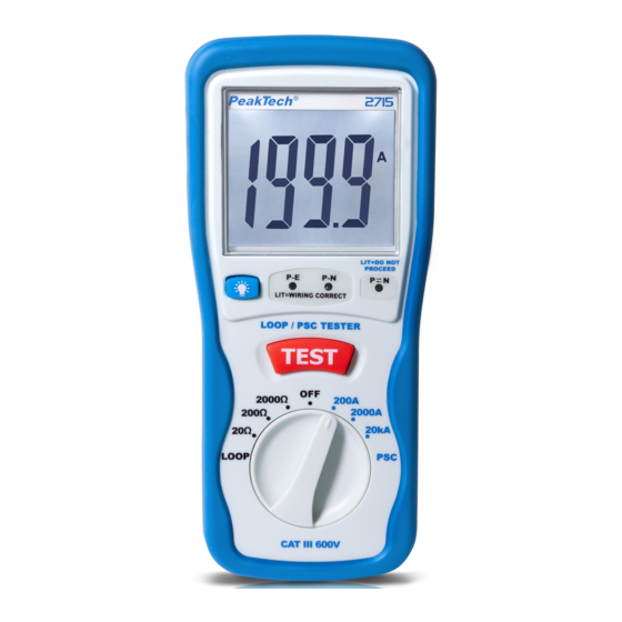
2. Bedienelemente ① Digitalanzeige ② Hintergrundbeleuchtung-Taste ③ P-E,P-N,Lichter ④ P-N REVERSE Licht ⑤ Testknopf ⑥ Drehschalter ⑦ POWER Buchse ⑧ Schlaufenhalter ⑨ Batteriedeckel... -
Seite 6: Anwendung
3. Anwendung Verbinden Sie das Gerät mit der zu messenden Schaltung. Überprüfen Sie den Zustand der Verdrahtung: Bevor Sie die Testtaste drücken, prüfen Sie den Status der 3 LED’s Status LED P<-N Aktion ● ● ○ Richtig verdrahtet Messung durchführen ○... -
Seite 7: Messung Der Schleifenimpedanz Und Des Kurzschl
4. Messung der Schleifenimpedanz und des Kurzschlussstroms Messen Schleifenimpedanz Fehlerstrom- oder Überstromschutzeinrichtungen. Gemäß IEC 60364, sollte jede Schleife dieser Formel entsprechen: Ra≤50/Ia Ra = Schleifenimpedanz 50 = max. Berührungsspannung Ia = Durch den Strom kann das Schutzgerät den Stromkreis in 5 Sekunden unterbrechen. -
Seite 8: Eigenschaften
5.Eigenschaften Netztest: 3 LED’s zeigen den Leitungszustand an. Wenn die Schaltung verpolt ist leuchtet die dritte LED. Überhitzungsschutz: Wenn die Temperatur des Widerstands zu hoch ist, wird der Tester abgeschaltet und gesperrt. Das LCD zeigt "Temperatur ist hoch" an und das folgende Symbol erscheint “... -
Seite 9: Spezifikationen
6. Spezifikationen Genauigkeiten werden wie folgt angegeben: ± (…% of reading +…digits) at 23°C ± 5°C,unter 80% RH. Schleifenwiderstand Messbereich Auflösung Testzeit Genauigkeit 20Ω 0.01Ω 25A/20ms ± 2% of F.S. ± 5 dgt. 200Ω 0.1Ω 2.3A/40ms ± 2% of F.S. ± 5 dgt. 2000Ω... -
Seite 10: Auswechselnd Der Batterien
7. Auswechseln der Batterie Wenn das Batteriesymbol ” ” auf dem LCD erscheint, müssen die sechs 1,5-V-AA-Batterien ersetzt werden. Schalten Sie das Messgerät aus und entfernen Sie die Messleitungen. Lösen Sie den Kippständer von der Rückseite des Geräts. ... - Seite 11 Letzter Stand bei Drucklegung. Technische Änderungen des Gerätes, welche dem Fortschritt dienen, vorbehalten. Hiermit bestätigen wir, dass alle Geräte, die in unseren Unterlagen genannten Spezifikationen erfüllen und werkseitig kalibriert geliefert werden. Eine Wiederholung der Kalibrierung nach Ablauf von 1 Jahr wird empfohlen. ® © PeakTech 06/2019 Ehr/Ham...