Inhaltsverzeichnis
Werbung
Verfügbare Sprachen
Verfügbare Sprachen
Werbung
Kapitel
Inhaltsverzeichnis

Verwandte Anleitungen für SICK T4000 series


Inhaltszusammenfassung für SICK T4000 series
- Seite 1 O P E R AT I N G I N S T R U C T I O N S T4000 Standard Safety Switch...
- Seite 2 Grenzen der gesetzlichen Bestimmungen des Urheberrechtsgesetzes zulässig. Eine Abände- rung oder Kürzung des Werkes ist ohne aus- drückliche schriftliche Zustimmung der Firma SICK AG untersagt. © SICK AG • Industrial Safety Systems • Deutschland • Irrtümer und Änderungen vorbehalten 8009704/XN71/2013-09-04...
-
Seite 3: Inhaltsverzeichnis
6.2 System-Zustandstabelle......23 6.3 Wiederkehrende technische Prüfungen ..........24 6.3.1 Regelmäßige Prüfungen....24 6.3.2 Prüfungen durch eine befähigte Person......25 6.4 Funktionsprüfung (Selbsttestung) ..25 8009704/XN71/2013-09-04 © SICK AG • Industrial Safety Systems • Deutschland • Irrtümer und Änderungen vorbehalten... - Seite 4 7.4 Betätiger T4000-1K......... 38 7.4.1 Maßzeichnung ......38 7.4.2 Technische Daten......38 Bestelldaten............ 39 8.1 Geräte ............39 8.2 Zubehör............ 39 Anhang............. 40 9.1 EG-Konformitätserklärung ...... 40 © SICK AG • Industrial Safety Systems • Deutschland • Irrtümer und Änderungen vorbehalten 8009704/XN71/2013-09-04...
-
Seite 5: Zu Diesem Dokument
Sicherheitsschalter T4000 ab- gesichert werden sollen. Sie richtet sich auch an Personen, die den T4000 in eine Maschine inte- grieren, erstmals in Betrieb nehmen oder technisch prüfen. 8009704/XN71/2013-09-04 © SICK AG • Industrial Safety Systems • Deutschland • Irrtümer und Änderungen vorbehalten... -
Seite 6: Informationstiefe
Leitfaden „Sichere Maschinen“. Nutzen Sie auch die Homepage im Internet unter Hinweis http://www.sick.com Dort finden Sie: Beispielapplikationen, Eine Liste häufiger Fragen zum T4000. © SICK AG • Industrial Safety Systems • Deutschland • Irrtümer und Änderungen vorbehalten 8009704/XN71/2013-09-04... -
Seite 7: Geltungsbereich
Warnhinweis Ein Warnhinweis weist Sie auf konkrete oder ACHTUNG potenzielle Gefahren hin. Dies soll Sie vor Unfällen bewahren. Lesen und befolgen Sie Warnhinweise sorgfältig! 8009704/XN71/2013-09-04 © SICK AG • Industrial Safety Systems • Deutschland • Irrtümer und Änderungen vorbehalten... - Seite 8 Bewegung eines Maschinenteiles dargestellt. In der Praxis kann es verschiedene Gefahr bringende Zustände geben: Maschinenbewegungen, Strom führende Teile, Sichtbare oder unsichtbare Strahlung, Eine Kombination mehrerer Gefahren. © SICK AG • Industrial Safety Systems • Deutschland • Irrtümer und Änderungen vorbehalten 8009704/XN71/2013-09-04...
-
Seite 9: Zur Sicherheit
Befähigt ist, wer über eine geeignete technische Ausbildung verfügt vom Maschinenbetreiber in der Bedienung und den gültigen Sicherheitsrichtlinien unterwiesen wurde Zugriff auf diese Betriebsanleitung hat. 8009704/XN71/2013-09-04 © SICK AG • Industrial Safety Systems • Deutschland • Irrtümer und Änderungen vorbehalten... -
Seite 10: Verwendungsbereiche Der Sicherheitsschalter
EN ISO 14119, Sicherheit von Maschinen – Verriegelungseinrichtungen in Verbindung mit trennenden Schutzeinrichtungen, EN 60204-1, Elektrische Ausrüstungen von Maschinen, EN 60947-5-3 Anforderungen für Näherungs- schalter mit definiertem Verhalten unter Fehlerbedingungen. © SICK AG • Industrial Safety Systems • Deutschland • Irrtümer und Änderungen vorbehalten 8009704/XN71/2013-09-04... -
Seite 11: Bestimmungsgemäße Verwendung
Art und Weise unwirksam gemacht werden. Haftungsausschluss bei: nicht bestimmungsgemäßem Gebrauch, Nichteinhaltung der Sicherheitshinweise, Anbau und elektrischem Anschluss durch nicht autorisiertes Personal, Fremdeingriff. 8009704/XN71/2013-09-04 © SICK AG • Industrial Safety Systems • Deutschland • Irrtümer und Änderungen vorbehalten... -
Seite 12: Systembeschreibung
Aufbau der Sicherheitselektronik in Verbindung mit zwei Sicher- heitsausgängen geht das Auswertegerät bei jedem erkennbaren Fehler in den sicheren Zustand über. © SICK AG • Industrial Safety Systems • Deutschland • Irrtümer und Änderungen vorbehalten 8009704/XN71/2013-09-04... - Seite 13 0,5 Sekunden betragen, ansonsten kann das Auswertegerät in den Fehlerzustand übergehen und die ERROR-LED leuchtet rot. Durch Unterbrechung der Spannungsversorgung wird das Auswertegerät in den Betriebszustand zurückgesetzt. 8009704/XN71/2013-09-04 © SICK AG • Industrial Safety Systems • Deutschland • Irrtümer und Änderungen vorbehalten...
-
Seite 14: Sicherheitsmerkmale
Funktionen. Unsachgemäßer Einbau oder Mani- pulationen können zu schweren Verletzungen von ACHTUNG Personen führen. Bei < 90.000 Schaltzyklen pro Jahr (siehe Kap. 7.2.3 „Technische Daten T4000-1RBA01“). © SICK AG • Industrial Safety Systems • Deutschland • Irrtümer und Änderungen vorbehalten 8009704/XN71/2013-09-04... -
Seite 15: Montage
Schaltschrank ohne Luftzirku- lation (z. B. Ventilator) ist zwischen den Auswerte- geräten ein Einbauabstand von 10 mm einzuhal- ten. Der Einbauabstand ermöglicht eine freie Wärmeableitung der Auswertegeräte. 8009704/XN71/2013-09-04 © SICK AG • Industrial Safety Systems • Deutschland • Irrtümer und Änderungen vorbehalten... -
Seite 16: Elektrischer Anschluss
23/24 zwingend auszuwerten. ACHTUNG Abb. 1: T4000-Auswerteger t Auswertung der Sicherheitsaus- Betriebsspannung gänge + 24 V Schirmanschluss braun Sensor Codierter Bet tiger Trans- ponder © SICK AG • Industrial Safety Systems • Deutschland • Irrtümer und Änderungen vorbehalten 8009704/XN71/2013-09-04... - Seite 17 Funktion zeigen (z. B. grüne STATE- LED leuchtet nicht), muss das Gerät ungeöffnet an den Hersteller zurückgesandt werden. Als Leitungsmaterial darf nur Kupfer mit einer Temperaturfestigkeit 75 °C verwendet werden. 8009704/XN71/2013-09-04 © SICK AG • Industrial Safety Systems • Deutschland • Irrtümer und Änderungen vorbehalten...
- Seite 18 Leitungsanschlüsse und damit eine einfache und schnelle Endmontage. Darüber hinaus bieten sie auch im Servicefall ein Höchstmaß an Sicher- heit. Abb. 3: Montage durch steckbare und codierte Klem- © SICK AG • Industrial Safety Systems • Deutschland • Irrtümer und Änderungen vorbehalten 8009704/XN71/2013-09-04...
-
Seite 19: Led-Anzeigen
– EMV Störung Bei Bedienungsfehler (ERROR) kann durch Unter- brechung der Spannungsversorgung – ca. 10 Se- kunden – das Auswertegerät in den Betriebszu- stand zurückgesetzt werden. 8009704/XN71/2013-09-04 © SICK AG • Industrial Safety Systems • Deutschland • Irrtümer und Änderungen vorbehalten... -
Seite 20: Inbetriebnahme Und Betrieb
Betätiger in einer Lernfunktion dem Auswertegerät zugeordnet werden. Während eines Lernvorganges sind die Sicherheits- ausgänge und der Tür-Meldeausgang auf LOW, d. h. das System befindet sich im sicheren Zustand. © SICK AG • Industrial Safety Systems • Deutschland • Irrtümer und Änderungen vorbehalten 8009704/XN71/2013-09-04... -
Seite 21: Lernfunktion Für Ersten Betätiger (Auslieferungszustand)
Code deaktiviert. Um den neu erlernten Code des Betätigers im Auswertegerät zu aktivieren, muss die Betriebs- spannung am Auswertegerät anschließend für min. 10 Sekunden abgeschaltet werden. 8009704/XN71/2013-09-04 © SICK AG • Industrial Safety Systems • Deutschland • Irrtümer und Änderungen vorbehalten... - Seite 22 In beiden Fällen wird ein Lernvorgang mit der Dauer von 60 Sekunden eingeleitet, der letzte Betätigercode bleibt jedoch im Speicher aktiv (siehe Kap. 6.2 „System-Zustandstabelle“), es wird kein neuer Code erlernt. © SICK AG • Industrial Safety Systems • Deutschland • Irrtümer und Änderungen vorbehalten 8009704/XN71/2013-09-04...
-
Seite 23: System-Zustandstabelle
= 0 oder 24 V bzw. Türe auf oder zu, LED aus , LED leuchtet, LED blinkt x beliebig Das Auswertegerät kann nur mit dem jeweils zuletzt Hinweis gelernten Betätiger betrieben werden. 8009704/XN71/2013-09-04 © SICK AG • Industrial Safety Systems • Deutschland • Irrtümer und Änderungen vorbehalten... -
Seite 24: Wiederkehrende Technische Prüfungen
Sitz der Leitungsanschlüsse am Sicherheits- Auswertegerät die Abschaltabstände überprüft werden. Wartungsarbeiten am batterielosen Betätiger sind nicht erforderlich und gewähren dem Anwender einen servicefreien Betrieb. © SICK AG • Industrial Safety Systems • Deutschland • Irrtümer und Änderungen vorbehalten 8009704/XN71/2013-09-04... -
Seite 25: Prüfungen Durch Eine Befähigte Person
Die Sicherheitsausgänge werden ausgeschaltet und damit die Testung des gesamten Sicherheitskreises ermöglicht. Als Überwachungsfunktion wird der Diagnoseausgang ERR vom Auswertegerät ebenfalls auf HIGH gesetzt. 8009704/XN71/2013-09-04 © SICK AG • Industrial Safety Systems • Deutschland • Irrtümer und Änderungen vorbehalten... -
Seite 26: Typischer Ansprechbereich (Bei Leitungslänge L = 0 Bis 25 M)
Hysterese „Sicherheitshinweise“) T4000-1RBA01 Sensor mit T4000- DNA... und Abschalt- Abstand S abstand T4000-1KBA Hysterese Einschalt- abstand S Mittenversatz m [mm] Min.-Max-Werte siehe Technische Daten. © SICK AG • Industrial Safety Systems • Deutschland • Irrtümer und Änderungen vorbehalten 8009704/XN71/2013-09-04... -
Seite 27: Technische Daten
Technische Daten Betriebsanleitung Kapitel T4000 Technische Daten Anschluss- und Blockschaltbild, Anschlussbeispiel Abb. 5: Anschluss- und Blockschaltbild, Anschlussbei- spiel Sicherheits-Relais Sicherheits-Relais 8009704/XN71/2013-09-04 © SICK AG • Industrial Safety Systems • Deutschland • Irrtümer und Änderungen vorbehalten... -
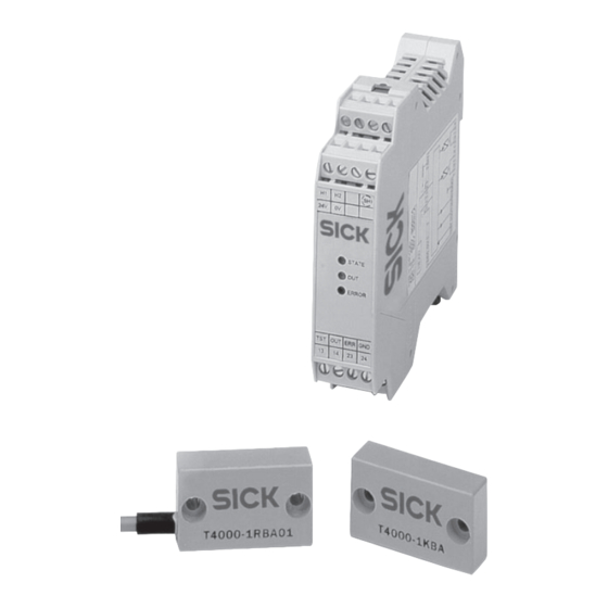
Seite 28: Auswertegerät T4000-1Rba01
Technische Daten Kapitel Betriebsanleitung T4000 Auswertegerät T4000-1RBA01 7.2.1 Maßzeichnung Abb. 6: Maßzeichnung 22,5 T4000-1RBA01 24V 0V STATE ERROR passend für Standard-Hutschiene 35 mm © SICK AG • Industrial Safety Systems • Deutschland • Irrtümer und Änderungen vorbehalten 8009704/XN71/2013-09-04... -
Seite 29: Schaltverhalten
= 24 V DC Lagertemperatur –25 °C – +70 °C Schutzart IP 20 Schutzklasse Schutzklasse III, Verschmutzungsgrad 2 Werkstoffgruppe IIIa Montage Hutschiene 35 mm nach EN 60715 8009704/XN71/2013-09-04 © SICK AG • Industrial Safety Systems • Deutschland • Irrtümer und Änderungen vorbehalten... - Seite 30 Kleinstrom (X 10 mA) mehr sicher schalten. Es ist sicherzustellen, dass Strom und Spannung so gewählt sind, dass eine Schaltleistung von mindestens 50 mW erreicht wird. © SICK AG • Industrial Safety Systems • Deutschland • Irrtümer und Änderungen vorbehalten 8009704/XN71/2013-09-04...
- Seite 31 Bei max. Schaltlast. Diskrepanzzeit ist die Differenzzeit der Schaltpunkte beider Relais. Entspricht nach EN 60947-5-3 der Risikozeit. Es ist die maximale Abschalt- verzögerung nach Entfernen des Betätigers. 8009704/XN71/2013-09-04 © SICK AG • Industrial Safety Systems • Deutschland • Irrtümer und Änderungen vorbehalten...
- Seite 32 Fehler im Auswertegerät (Selbstüberwachung) zu gewährleisten. Bei einer Strombelastung > 100 mA sollte aufgrund der Lebensdauer der Relaiskontakte eine Schaltfrequenz von 0,1 Hz nicht überschritten werden. Nicht kurzschlusssicher. © SICK AG • Industrial Safety Systems • Deutschland • Irrtümer und Änderungen vorbehalten 8009704/XN71/2013-09-04...
-
Seite 33: Sensoren T4000-Dn
Maßzeichnung Leitungslänge l T4000-DNA..P T 4000-D XXXXXX aktive aktive ±0,1 Fläche Fläche Anschlussbelegung Abb. 9: Sensor mit Anschlussleitung Schirm Anschlussbele- gung T4000- Sensor DNA..P Auswertegerät 8009704/XN71/2013-09-04 © SICK AG • Industrial Safety Systems • Deutschland • Irrtümer und Änderungen vorbehalten... -
Seite 34: Sensor T4000-Dn.c Mit Steckverbinder M8 (Mit Rast- Und Schraubanschluss)
T4000-DNBC T 4000-DN.. aktive min. 38 Fläche Anschlussbelegung Abb. 11: Sensor mit Steckverbinder Anschlussbele- Schirm gung T4000- DNAC/ Ansicht auf T4000-DNBC Steckverbinder des Sensors Auswertegerät © SICK AG • Industrial Safety Systems • Deutschland • Irrtümer und Änderungen vorbehalten 8009704/XN71/2013-09-04... -
Seite 35: Technische Daten
5 mm – – abstand s – Schalthysterese 0,5 mm 1,5 mm – Diese Werte gelten für bündigen Einbau des Sensors und des Betätigers in Aluminium. 8009704/XN71/2013-09-04 © SICK AG • Industrial Safety Systems • Deutschland • Irrtümer und Änderungen vorbehalten... -
Seite 36: Montagehinweise Sensor Und Betätiger
Technische Daten) gegenüberliegen. sie nicht als mechanischer Anschlag verwendet werden, sie formschlüssig mit der Schutzeinrichtung verbunden sind, z. B. durch die Verwendung der beiliegenden Sicherheitsschrauben. © SICK AG • Industrial Safety Systems • Deutschland • Irrtümer und Änderungen vorbehalten 8009704/XN71/2013-09-04... -
Seite 37: Sicherheitshinweise
Abstand s (sicherer Abschaltab- stand) eine Gefährdung ausgeschlossen ist. Beim sicheren Abschaltabstand s sind die Relais- Hinweis ausgänge, auch bei einem internen Bauteilausfall, sicher ausgeschaltet. 8009704/XN71/2013-09-04 © SICK AG • Industrial Safety Systems • Deutschland • Irrtümer und Änderungen vorbehalten... -
Seite 38: Betätiger T4000-1K
Fläche gegenüber Sensor Verweildauer 0,5 s – – Die Verweildauer ist die Zeit, in der sich der Betätiger innerhalb oder außerhalb des Ansprechbereichs befinden muss. © SICK AG • Industrial Safety Systems • Deutschland • Irrtümer und Änderungen vorbehalten 8009704/XN71/2013-09-04... -
Seite 39: Bestelldaten
T4000-DNA10W 6034393 Stecker gewinkelt Anschlussleitung 25 m, T4000-DNA25W 6034394 Stecker gewinkelt Anschlussleitung 50 m, T4000-DNA50W 6034395 Stecker gewinkelt Sicherheitsschrauben für 20 Stück 5309170 Sensor und Betätiger 8009704/XN71/2013-09-04 © SICK AG • Industrial Safety Systems • Deutschland • Irrtümer und Änderungen vorbehalten... -
Seite 40: Anhang
Gustav-Heinemann-Ufer 130, 50968 Köln, Germany Kennnummer der notifizierten Prüfstelle: 0340 Nummer der EG-Baumusterprüfbescheinigung: ET10132 Die unterzeichnete EG-Konformitätserklärung finden Sie unter: www.sick.com. Suchen Sie nach: 9056835 © SICK AG • Industrial Safety Systems • Deutschland • Irrtümer und Änderungen vorbehalten 8009704/XN71/2013-09-04... - Seite 41 Anhang Betriebsanleitung Kapitel T4000 8009704/XN71/2013-09-04 © SICK AG • Industrial Safety Systems • Deutschland • Irrtümer und Änderungen vorbehalten...
- Seite 42 Está prohi- bida la modificación o la abreviación del docu- mento, sin la autorización expresa por escrito de la empresa SICK AG. © SICK AG • Industrial Safety Systems • Alemania • Sujeto a cambio sin previo aviso 8009704/XN71/2013-09-04...
- Seite 43 6.3 Comprobaciones técnicas periódicas..64 6.3.1 Comprobaciones periódicas..64 6.3.2 Comprobaciones a cargo de una persona cualificada....65 6.4 Prueba de función (autotest) ....65 8009704/XN71/2013-09-04 © SICK AG • Industrial Safety Systems • Alemania • Sujeto a cambio sin previo aviso...
- Seite 44 Datos para el pedido ........79 8.1 Equipos ............ 79 8.2 Accesorios..........79 Anexo ............... 80 9.1 Declaración de conformidad CE ..... 80 © SICK AG • Industrial Safety Systems • Alemania • Sujeto a cambio sin previo aviso 8009704/XN71/2013-09-04...
-
Seite 45: Respecto A Este Documento
También van dirigidas a aquellas personas que integren el T4000 en una máquina, o que pongan ésto en servicio por primera vez o lleven a cabo su mantenimiento. 8009704/XN71/2013-09-04 © SICK AG • Industrial Safety Systems • Alemania • Sujeto a cambio sin previo aviso... -
Seite 46: Alcance De Las Informaciones
Consulte asimismo la página web de SICK en la Indicación siguiente dirección de Internet http://www.sick.com Allí encontrará: Ejemplos de aplicaciones, Una lista con las cuestiones más frecuentes acerca del T4000. © SICK AG • Industrial Safety Systems • Alemania • Sujeto a cambio sin previo aviso 8009704/XN71/2013-09-04... -
Seite 47: Ámbito De Validez
… flecha. Lea detenidamente y cumpla con esmero las instrucciones sobre las acciones a realizar. 8009704/XN71/2013-09-04 © SICK AG • Industrial Safety Systems • Alemania • Sujeto a cambio sin previo aviso... - Seite 48 En la práctica se pueden dar distin- tos estados peligrosos: Movimientos de la máquina, Piezas conductoras de electricidad, Radiación visible o invisible, Una combinación de varios peligros. © SICK AG • Industrial Safety Systems • Alemania • Sujeto a cambio sin previo aviso 8009704/XN71/2013-09-04...
-
Seite 49: Respecto A La Seguridad
8009704/XN71/2013-09-04 © SICK AG • Industrial Safety Systems • Alemania • Sujeto a cambio sin previo aviso... -
Seite 50: Ámbitos De Aplicación De Los Interruptores De Seguridad
EN 60204-1, equipamiento eléctrico de máquinas, EN 60947-5-3, exigencias para detectores de aproximación con comportamiento definido ante condiciones de error. © SICK AG • Industrial Safety Systems • Alemania • Sujeto a cambio sin previo aviso 8009704/XN71/2013-09-04... -
Seite 51: Utilización Conforme Al Fin Previsto
8009704/XN71/2013-09-04 © SICK AG • Industrial Safety Systems • Alemania • Sujeto a cambio sin previo aviso... -
Seite 52: Descripción Del Sistema
© SICK AG • Industrial Safety Systems • Alemania • Sujeto a cambio sin previo aviso 8009704/XN71/2013-09-04... - Seite 53 LED ERROR rojo se enciende. Interrumpiendo el abastecimiento de tensión, el aparato evaluador se repone al esta- do de servicio. 8009704/XN71/2013-09-04 © SICK AG • Industrial Safety Systems • Alemania • Sujeto a cambio sin previo aviso...
-
Seite 54: Características De Seguridad
ATENCIÓN ves lesiones a personas. Con < 90.000 ciclos de maniobra por año (ver capitulo 7.2.3 „Datos técnicos T4000-1RBA01“) © SICK AG • Industrial Safety Systems • Alemania • Sujeto a cambio sin previo aviso 8009704/XN71/2013-09-04... -
Seite 55: Montaje
10 mm entre los aparatos evaluadores. La distancia de montaje permite disipar libremente el calor de los aparatos evaluadores. 8009704/XN71/2013-09-04 © SICK AG • Industrial Safety Systems • Alemania • Sujeto a cambio sin previo aviso... -
Seite 56: Conexión Eléctrica
Evaluación de las salidas de Tensión de operación + 24 V seguridad c.c. Conexión de blindaje marrón blanco Sensor Actuador codificado Trans- ponder © SICK AG • Industrial Safety Systems • Alemania • Sujeto a cambio sin previo aviso 8009704/XN71/2013-09-04... - Seite 57 Como material conductor sólo deberá emplearse cobre de termorresistencia 75 °C. Los tornillos de los bornes de conexión deberán apretarse a par de apriete de 0,6–0,8 Nm. 8009704/XN71/2013-09-04 © SICK AG • Industrial Safety Systems • Alemania • Sujeto a cambio sin previo aviso...
- Seite 58 Además, los bornes ofrecen un grado máximo de seguridad en caso de servicio. Fig. 3: Montaje median- te terminales enchufables y codificados © SICK AG • Industrial Safety Systems • Alemania • Sujeto a cambio sin previo aviso 8009704/XN71/2013-09-04...
- Seite 59 En caso de manejo incorrecto (ERROR) es posible reposicionar el aparato evaluador a su estado de operación, interrumpiendo la alimentación de tensión durante unos 10 segundos. 8009704/XN71/2013-09-04 © SICK AG • Industrial Safety Systems • Alemania • Sujeto a cambio sin previo aviso...
-
Seite 60: Puesta En Servicio Y Funcionamiento
LOW, es decir que el sistema se encuentra en un estado seguro. © SICK AG • Industrial Safety Systems • Alemania • Sujeto a cambio sin previo aviso 8009704/XN71/2013-09-04... -
Seite 61: Función De Aprendizaje Para El Primer Actuador (Estado De Entrega)
Para activar el código nuevo aprendido del actuador en el aparato evaluador, es necesario desconectar ahora la tensión de operación por lo menos durante 10 segundos. 8009704/XN71/2013-09-04 © SICK AG • Industrial Safety Systems • Alemania • Sujeto a cambio sin previo aviso... - Seite 62 60 segundos, sin embargo, el último código de actuador permanece activo en la memoria (ver capítulo 6.2 “Tabla de estados del sistema”), no se aprenderá un código nuevo. © SICK AG • Industrial Safety Systems • Alemania • Sujeto a cambio sin previo aviso 8009704/XN71/2013-09-04...
-
Seite 63: Tabla De Estados Del Sistema
N = 0 voltios o no conectado, 0 = 0 voltios, 1 = 24 voltios, x = 0 ó 24 voltios o bien puerta abierta o cerrada, LED off , LED luce, LED parpadea x aleatorio 8009704/XN71/2013-09-04 © SICK AG • Industrial Safety Systems • Alemania • Sujeto a cambio sin previo aviso... -
Seite 64: Comprobaciones Técnicas Periódicas
El actuador codificado no incorpora baterias ni pilas no necesita trabajos de mantenimiento, permitien- do al usuario una operación exenta de manteni- miento. © SICK AG • Industrial Safety Systems • Alemania • Sujeto a cambio sin previo aviso 8009704/XN71/2013-09-04... -
Seite 65: Comprobaciones A Cargo De Una Persona Cualificada
Como función de control el aparato evaluador pone igualmente la salida de diagnóstico ERR a HIGH. 8009704/XN71/2013-09-04 © SICK AG • Industrial Safety Systems • Alemania • Sujeto a cambio sin previo aviso... -
Seite 66: Rango De Actuación (Con Una Longitud Del Cable L = 0 A 25 M)
Distancia de Distancia s desconexión Histéresis Desconectado Desconectado Distancia de conexión S Conectado Desplazamiento de centros en m [mm] Valores máx./mín, v. Datos técnicos © SICK AG • Industrial Safety Systems • Alemania • Sujeto a cambio sin previo aviso 8009704/XN71/2013-09-04... -
Seite 67: Datos Técnicos
Datos técnicos Diagrama de conexiones y de bloques, ejemplo de conexión Fig. 5: Diagrama de conexiones y de bloques, ejemplo c.c. de conexión 8009704/XN71/2013-09-04 © SICK AG • Industrial Safety Systems • Alemania • Sujeto a cambio sin previo aviso... -
Seite 68: Aparato Evaluador T4000-1Rba01
T4000-1RBA 01 (actuador reconocido) (actuador no enzona de reacción) Sensor Actuador Sensor 24 V O UT 24 V O UT © SICK AG • Industrial Safety Systems • Alemania • Sujeto a cambio sin previo aviso 8009704/XN71/2013-09-04... -
Seite 69: Datos Técnicos T4000-1Rba01
AC 30 V Class 2/ ción en base a max. DC 60 V Class 2 Fusibles externos – 0,25 A – (Voltaje operativo U 8009704/XN71/2013-09-04 © SICK AG • Industrial Safety Systems • Alemania • Sujeto a cambio sin previo aviso... - Seite 70 Hay que asegurarse de que se hayan seleccionado una intensidad y una tensión con las que se alcance una capacidad de conmutación de 50 mW como mínimo. © SICK AG • Industrial Safety Systems • Alemania • Sujeto a cambio sin previo aviso 8009704/XN71/2013-09-04...
- Seite 71 El tiempo de discrepancia es la diferencia que hay entre los instantes de conmutación de ambos relés. 8009704/XN71/2013-09-04 © SICK AG • Industrial Safety Systems • Alemania • Sujeto a cambio sin previo aviso...
- Seite 72 Con una carga de corriente > 100 mA, considerando la vida útil de los contactos de relé no se debería rebasar un frecuencia de conmutación de 0,1 Hz. No está a prueba de cortocircuito. © SICK AG • Industrial Safety Systems • Alemania • Sujeto a cambio sin previo aviso 8009704/XN71/2013-09-04...
- Seite 73 LED amarillo: Detección del actuador ERROR LED rojo: – Test de entrada activado – Error interno de circuito – Operación de aprendizaje invalidada – Perturbación CEM 8009704/XN71/2013-09-04 © SICK AG • Industrial Safety Systems • Alemania • Sujeto a cambio sin previo aviso...
-
Seite 74: Sensores T4000-Dn
M8 (con conector de muesca y roscado) Dibujo acotado Fig. 10: Dibujo acotado 32,6 T4000-DNAC/ 32 ±0,1 T4000-DNBC T 4000-DN.. Superficie min. 38 activa © SICK AG • Industrial Safety Systems • Alemania • Sujeto a cambio sin previo aviso 8009704/XN71/2013-09-04... -
Seite 75: Datos Técnicos
– +60 °C Temperatura am- biental T4000-DNBC Protección ambiental IP 67/IP 69k Transferencia de 2 kbit/s datos dinámica a la unidad de evaluación 8009704/XN71/2013-09-04 © SICK AG • Industrial Safety Systems • Alemania • Sujeto a cambio sin previo aviso... - Seite 76 Conexión del sensor Cable de conexión permanentemente T4000-DNA..P sellado y manguitos Estos valores rigen para el montaje enrasado del sensor y el actuador en aluminio. © SICK AG • Industrial Safety Systems • Alemania • Sujeto a cambio sin previo aviso 8009704/XN71/2013-09-04...
-
Seite 77: Indicaciones Para El Montaje De Sensor Y Actuador
El dispositivo de protección debe estar diseñado de tal modo que se excluya todo riesgo hasta la distancia S (distancia segura de desconexión). 8009704/XN71/2013-09-04 © SICK AG • Industrial Safety Systems • Alemania • Sujeto a cambio sin previo aviso... -
Seite 78: Actuador T4000-1Kba
El tiempo de espera es el tiempo en el que se debe encontrar el actuador dentro o fuera de la zona de reacción. © SICK AG • Industrial Safety Systems • Alemania • Sujeto a cambio sin previo aviso 8009704/XN71/2013-09-04... -
Seite 79: Datos Para El Pedido
Cable de conexión 50 m, T4000-DNA50W 6034395 conector acodado Tornillos de seguridad para 20 piezas 5309170 el sensor y el actuador 8009704/XN71/2013-09-04 © SICK AG • Industrial Safety Systems • Alemania • Sujeto a cambio sin previo aviso... -
Seite 80: Anexo
0340 Número del certificado de ensayo de homologación CE: ET10132 Encontrará la declaración de conformidad CE firmada en: www.sick.com. Busque: 9056835 © SICK AG • Industrial Safety Systems • Alemania • Sujeto a cambio sin previo aviso 8009704/XN71/2013-09-04... - Seite 81 Anexo Instruccion de servicio Capítulo T4000 8009704/XN71/2013-09-04 © SICK AG • Industrial Safety Systems • Alemania • Sujeto a cambio sin previo aviso...
- Seite 82 Toute modification ou abréviation de l’ouvrage doit faire l’objet d’un accord écrit préalable de la société SICK AG. © SICK AG • Industrial Safety Systems • Allemagne • Sujet à modification sans préavis 8009704/XN71/2013-09-04...
- Seite 83 6.3 Contrôle périodique technique ..... 104 6.3.1 Contrôles périodiques ....104 6.3.2 Contrôles par un personnel qualifié........105 6.4 Contrôle du fonctionnement (auto- test) ............105 8009704/XN71/2013-09-04 © SICK AG • Industrial Safety Systems • Allemagne • Sujet à modification sans préavis...
- Seite 84 7.4.2 Caractéristiques techniques ..119 Références ............ 120 8.1 Appareils ..........120 8.2 Accessoires ..........120 Annexe............121 9.1 Déclaration CE de conformité ....121 © SICK AG • Industrial Safety Systems • Allemagne • Sujet à modification sans préavis 8009704/XN71/2013-09-04...
-
Seite 85: Propos De Ce Manuel
également aux personnes qui intègrent le T4000 dans une machine ou qui effectuent une première mise en service ou une contrôle techni- que. 8009704/XN71/2013-09-04 © SICK AG • Industrial Safety Systems • Allemagne • Sujet à modification sans préavis... -
Seite 86: Étendue Des Informations Fournies
Consulter également le site Internet SICK à Remarque l’adresse http://www.sick.com Il comporte : des exemples d’application, une liste des questions les plus fréquemment posées sur le T4000. © SICK AG • Industrial Safety Systems • Allemagne • Sujet à modification sans préavis 8009704/XN71/2013-09-04... -
Seite 87: Disponibilité Des Fonctions
Les avertissements servent à signaler un risque ATTENTION potentiel ou existant. Un avertissement est destiné à la protection contre les accidents. Ils doivent être lus et suivis scrupuleusement ! 8009704/XN71/2013-09-04 © SICK AG • Industrial Safety Systems • Allemagne • Sujet à modification sans préavis... - Seite 88 Dans la pratique, plusieurs cas de « situations dangereuses » peuvent se présenter : mouvements de la machine, conducteurs sous tension, rayonnement visible ou invisible, association de plusieurs risques. © SICK AG • Industrial Safety Systems • Allemagne • Sujet à modification sans préavis 8009704/XN71/2013-09-04...
-
Seite 89: La Sécurité
2009/104/CE sur les prescriptions de sécurité concernant l’utilisation des équipements de travail, les prescriptions de prévention des accidents et les règlements de sécurité. 8009704/XN71/2013-09-04 © SICK AG • Industrial Safety Systems • Allemagne • Sujet à modification sans préavis... -
Seite 90: Qualification Du Personnel
EN ISO 14121-1, Sécurité des machines, appréciation du risque. L’utilisation conforme implique le respect des exigences applicables au montage et à la mise en service, et en particulier © SICK AG • Industrial Safety Systems • Allemagne • Sujet à modification sans préavis 8009704/XN71/2013-09-04... -
Seite 91: Conformité D'utilisation
Pour toute autre utilisation, aussi bien que pour les modifications, y compris concernant le montage et l’installation, la responsabilité de la société SICK AG ne saurait être invoquée. 8009704/XN71/2013-09-04 © SICK AG • Industrial Safety Systems • Allemagne • Sujet à modification sans préavis... -
Seite 92: Consignes De Sécurité Et Mesures De Protection D'ordre Général
Toute responsabilité est exclue en cas de : utilisation non conforme à la réglementation, non-respect des consignes de sécurité, montage et raccordement électrique par du per- sonnel non habilité, intervention extérieure. © SICK AG • Industrial Safety Systems • Allemagne • Sujet à modification sans préavis 8009704/XN71/2013-09-04... -
Seite 93: Description Du Système
(OUT) est commutée en niveau bas. L’état des sorties de sécurité est 8009704/XN71/2013-09-04 © SICK AG • Industrial Safety Systems • Allemagne • Sujet à modification sans préavis... -
Seite 94: Caractéristiques De Sécurité
ATTENTION être à l’origine de blessures graves. Pour < 90.000 cycles de commutation par an (cf. chapitre. 7.2.3 «Caractéristiques techniques T4000-1RBA01»). © SICK AG • Industrial Safety Systems • Allemagne • Sujet à modification sans préavis 8009704/XN71/2013-09-04... -
Seite 95: Montage
10 mm doit être respecter entre les analyseurs. La distance d’implantation permet la libre dissipation de la chaleur dégagée par l’électronique. 8009704/XN71/2013-09-04 © SICK AG • Industrial Safety Systems • Allemagne • Sujet à modification sans préavis... -
Seite 96: Raccordement Électrique
Analyseur T4000 Analyse des sor- ties de sécurité Tension de service + 24 V Raccordement du blindage Brun Blanc Capteur Actionneur codé Trans- pondeur © SICK AG • Industrial Safety Systems • Allemagne • Sujet à modification sans préavis 8009704/XN71/2013-09-04... - Seite 97 à une température 75 °C. Serrer les vis des bornes de raccordement avec un couple de 0,6 à 0,8 Nm. 8009704/XN71/2013-09-04 © SICK AG • Industrial Safety Systems • Allemagne • Sujet à modification sans préavis...
- Seite 98 Elles offrent également une sécurité maximale pour la maintenance. Fig. 3: Montage par bornes enfichab- les et codées © SICK AG • Industrial Safety Systems • Allemagne • Sujet à modification sans préavis 8009704/XN71/2013-09-04...
- Seite 99 En cas d’erreur de manipulation (ERROR), l’ana- lyseur peut être remis en état de fonctionner en coupant la tension d’alimentation pendant environ 10 secondes. 8009704/XN71/2013-09-04 © SICK AG • Industrial Safety Systems • Allemagne • Sujet à modification sans préavis...
-
Seite 100: Contrôles Et Mise En Service
Lors d’un processus d’apprentissage, les sorties de sécurité et la sortie d’alarme de la porte sont en niveau bas, c’est-à-dire que le système se trouve en position sûre. © SICK AG • Industrial Safety Systems • Allemagne • Sujet à modification sans préavis 8009704/XN71/2013-09-04... -
Seite 101: Fonction D'apprentissage Pour Le Premier Actionneur (État D'origine)
Pour activer le nouveau code appris de l’actionneur dans l’analyseur, la tension de service de l’analyseur doit ensuite être déconnectée pendant au moins 10 secondes. 8009704/XN71/2013-09-04 © SICK AG • Industrial Safety Systems • Allemagne • Sujet à modification sans préavis... - Seite 102 60 secondes est démarré mais le dernier code d’actionneur reste actif dans la mémoire (cf. chapitre 6.2 « Tableau des états du système »). Un nouveau code n’est pas appris. © SICK AG • Industrial Safety Systems • Allemagne • Sujet à modification sans préavis 8009704/XN71/2013-09-04...
-
Seite 103: Tableau Des États Du Système
N = 0 volt ou non connecté, 0 volt; 1= 24 volts, x = 0 ou 24 volts et porte ouverte ou fermée, LED éteinte , LED allumée, LED clignote x indifférent 8009704/XN71/2013-09-04 © SICK AG • Industrial Safety Systems • Allemagne • Sujet à modification sans préavis... -
Seite 104: Contrôle Périodique Technique
Aucun entretien n’est nécessaire au niveau de l’ac- tionneur (qui ne possède pas de pile), d’où la ga- rantie pour l’utilisateur d’un fonctionnement sans maintenance. © SICK AG • Industrial Safety Systems • Allemagne • Sujet à modification sans préavis 8009704/XN71/2013-09-04... -
Seite 105: Contrôles Par Un Personnel Qualifié
La sortie de diagnostic ERR de l’analy- seur est aussi placée en niveau haut comme fonc- tion de surveillance. 8009704/XN71/2013-09-04 © SICK AG • Industrial Safety Systems • Allemagne • Sujet à modification sans préavis... -
Seite 106: Zone De Déclenchement Type (Avec Une Longueur De Câble L = 0 À 25 M)
Distance de Distance s déconnexion T4000-1KBA Hysteresis ARRET ARRET Distance de connexion S MARCHE Déport des axes m [mm] Valeurs mini./maxi. : cf. Caractéristiques techniques © SICK AG • Industrial Safety Systems • Allemagne • Sujet à modification sans préavis 8009704/XN71/2013-09-04... -
Seite 107: Caractéristiques Techniques
Chapitre T4000 Caractéristiques techniques Schéma de raccordement et synoptique modulaire, exemple de raccordement Fig. 5: Schéma de raccordement et synoptique modulaire, exemple de raccordement 8009704/XN71/2013-09-04 © SICK AG • Industrial Safety Systems • Allemagne • Sujet à modification sans préavis... -
Seite 108: Analyseur T4000-1Rba01
Caractéristiques techniques Chapitre Notice d'instructions T4000 Analyseur T4000-1RBA01 7.2.1 Schéma coté Fig. 6: Schéma coté T4000-1RBA01 pour profilé chapeau standard 35 mm © SICK AG • Industrial Safety Systems • Allemagne • Sujet à modification sans préavis 8009704/XN71/2013-09-04... -
Seite 109: Schèma De Commutation
IP 20 Classe de protection classe de protection III, degré de pollution 2 Groupe de matériaux IIIa Montage profilé 35 mm suivant EN 60715 8009704/XN71/2013-09-04 © SICK AG • Industrial Safety Systems • Allemagne • Sujet à modification sans préavis... - Seite 110 (a10 mA). Il faut s’assurer que le courant et la tension choisis correspondent à un pouvoir de commutation minimal de 50 mW. © SICK AG • Industrial Safety Systems • Allemagne • Sujet à modification sans préavis 8009704/XN71/2013-09-04...
- Seite 111 EN 60947-5-3 Tension nominale – – 63 V d’isolement U – – 1,5 kV Résistance de tension impulsionnelle U Pour la charge de commutation max. 8009704/XN71/2013-09-04 © SICK AG • Industrial Safety Systems • Allemagne • Sujet à modification sans préavis...
- Seite 112 En cas de charge électrique > 100 mA, éviter de dépasser une fréquence de commutation de 0,1 Hz en raison de la durée de vie des contacts relais. © SICK AG • Industrial Safety Systems • Allemagne • Sujet à modification sans préavis 8009704/XN71/2013-09-04...
- Seite 113 LED jaune : actionneur reconnu ERROR LED rouge : – entrée de test activée – défaut interne électronique – apprentissage incorrect – perturbation CEM 8009704/XN71/2013-09-04 © SICK AG • Industrial Safety Systems • Allemagne • Sujet à modification sans préavis...
-
Seite 114: Capteurs T4000-Dn
T 4000-D XXXXXX surface surface active active ±0,1 Affectation des broches Fig. 9: Capteur avec câble de raccordement Blindage Affectation des broches T4000- Capteur DNA..P Analyseur © SICK AG • Industrial Safety Systems • Allemagne • Sujet à modification sans préavis 8009704/XN71/2013-09-04... -
Seite 115: Capteur T4000-Dn.c Avec Connecteur Mâle M8 (Connecteur Enfichable/Vis Filetée)
38 Affectation des broches Fig. 11: Capteur avec connecteur mâle Affectation des Blindage broches T4000- DNAC/T4000- DNBC Vue du connecteur mâle du capteur Analyseur 8009704/XN71/2013-09-04 © SICK AG • Industrial Safety Systems • Allemagne • Sujet à modification sans préavis... -
Seite 116: Caractéristiques Techniques
1,2 mm – Alimentation en tension par l’analyseur Ces valeurs sont valables pour un montage à affleurant du capteur et de l’actionneur dans de l’aluminium. © SICK AG • Industrial Safety Systems • Allemagne • Sujet à modification sans préavis 8009704/XN71/2013-09-04... -
Seite 117: Instructions De Montage Capteur Et Actionneur
8009704/XN71/2013-09-04 © SICK AG • Industrial Safety Systems • Allemagne • Sujet à modification sans préavis... -
Seite 118: Consignes De Sécurité
A la distance de déconnexion sûre s , les sorties Remarque relais sont déconnectées de manière sûre même en cas de défaillance d’un composant interne. © SICK AG • Industrial Safety Systems • Allemagne • Sujet à modification sans préavis 8009704/XN71/2013-09-04... -
Seite 119: Actionneur T4000-1Kba
La durée de contact correspond à la période pendant laquelle l’actionneur doit se trouver à l’intérieur ou à l’extérieur de la zone de détection. 8009704/XN71/2013-09-04 © SICK AG • Industrial Safety Systems • Allemagne • Sujet à modification sans préavis... -
Seite 120: Références
Câble de raccordement 50 m, T4000-DNA50W 6034395 connecteur mâle coudé Vis de sécurité pour capteur et lot de 20 5309170 actionneur © SICK AG • Industrial Safety Systems • Allemagne • Sujet à modification sans préavis 8009704/XN71/2013-09-04... -
Seite 121: Annexe
Numéro du certificat CE de type : ET10132 La déclaration CE de conformité signée est disponible page : www.sick.com. Rechercher le numéro : 9056835 8009704/XN71/2013-09-04 © SICK AG • Industrial Safety Systems • Allemagne • Sujet à modification sans préavis... - Seite 122 Copyright Law. Alteration or abridgement of the document is not permitted without the explicit written approval of the company SICK AG. © SICK AG • Industrial Safety Systems • Germany • Subject to change without notice 8009704/XN71/2013-09-04...
- Seite 123 6.5 Typical operating range (with cable length l = 0 to 25 m)......145 6.5.1 Evaluation unit T4000- 1RBA01 with sensor T4000- DNA... and T4000-1KBA.... 145 8009704/XN71/2013-09-04 © SICK AG • Industrial Safety Systems • Germany • Subject to change without notice...
- Seite 124 7.4.1 Dimensional drawing....157 7.4.2 Technical data ......157 Ordering information........158 8.1 Devices........... 158 8.2 Accessories ..........158 Appendix............159 9.1 EC declaration of conformity....159 © SICK AG • Industrial Safety Systems • Germany • Subject to change without notice 8009704/XN71/2013-09-04...
-
Seite 125: About This Document
T4000 safety switches. They also address people who integrate the T4000 into a machine, initialise its use, or who are in charge of testing the device. 8009704/XN71/2013-09-04 © SICK AG • Industrial Safety Systems • Germany • Subject to change without notice... -
Seite 126: Depth Of Information
We also refer you to the SICK homepage in the Note Internet at http://www.sick.com Here you will find information on: Sample applications, A list of frequently asked questions regarding the T4000. © SICK AG • Industrial Safety Systems • Germany • Subject to change without notice 8009704/XN71/2013-09-04... -
Seite 127: Scope
A warning notice indicates an actual or potential WARNING risk or health hazard. They are designed to help you to prevent accidents. Always read warnings attentively and follow instructions carefully! 8009704/XN71/2013-09-04 © SICK AG • Industrial Safety Systems • Germany • Subject to change without notice... - Seite 128 In practical operation, there may be a number of different dangerous states: Machine movements, electrical conductors, visible or invisible radiation, a combination of several hazards. © SICK AG • Industrial Safety Systems • Germany • Subject to change without notice 8009704/XN71/2013-09-04...
-
Seite 129: On Safety
8009704/XN71/2013-09-04 © SICK AG • Industrial Safety Systems • Germany • Subject to change without notice... -
Seite 130: Applications Of The Safety Switches
EN ISO 14119, Safety of Machinery – Interlocking Devices Associated with Guards, EN 60204-1, Electrical Equipment of Machines, EN 60947-5-3, Requirements for Proximity Devices with Defined Behaviour under Error Conditions. © SICK AG • Industrial Safety Systems • Germany • Subject to change without notice 8009704/XN71/2013-09-04... -
Seite 131: Correct Use
Liability is excluded in case of: incorrect use, failure to comply with the safety notes, installation and electrical connection by unauthorised personnel, unauthorised modifications. 8009704/XN71/2013-09-04 © SICK AG • Industrial Safety Systems • Germany • Subject to change without notice... -
Seite 132: System Description
(OUT) is switched to LOW. The status of the normally open contacts is monitored internally via positive-action normally closed contacts. © SICK AG • Industrial Safety Systems • Germany • Subject to change without notice 8009704/XN71/2013-09-04... -
Seite 133: Safety Features
Incorrect installation or tampering may lead to serious injury. WARNING At < 90.000 switching operations per year (see chapter 7.2.3 “Technical data T4000-1RBA01”). 8009704/XN71/2013-09-04 © SICK AG • Industrial Safety Systems • Germany • Subject to change without notice... -
Seite 134: Mounting
(e.g. fan) is provided, there must be a gap of 10 mm between the evaluation units. The clearance enables heat to be dissipated from the evaluation units. © SICK AG • Industrial Safety Systems • Germany • Subject to change without notice 8009704/XN71/2013-09-04... -
Seite 135: Electrical Connection
Fig. 1: Evaluation of the T 4000 Evaluation Unit safety outputs Operating voltage + 24 V Screen terminal brown white Sensor Coded actuator Trans- ponder 8009704/XN71/2013-09-04 © SICK AG • Industrial Safety Systems • Germany • Subject to change without notice... - Seite 136 75 °C may be used for the wiring. The screws for the connecting terminal must be tightened to a tightening torque of 0.6 to 0.8 Nm. © SICK AG • Industrial Safety Systems • Germany • Subject to change without notice 8009704/XN71/2013-09-04...
- Seite 137 They also provide maximum safety during servicing. Fig. 3: Mounting using plug-in, coded terminals 8009704/XN71/2013-09-04 © SICK AG • Industrial Safety Systems • Germany • Subject to change without notice...
-
Seite 138: Led Indicators
In the event of operating errors (ERROR), the evaluation unit can be reset to operating state by interrupting the supply voltage for approx. 10 seconds. © SICK AG • Industrial Safety Systems • Germany • Subject to change without notice 8009704/XN71/2013-09-04... -
Seite 139: Commissioning And Operation
During the Teach-in operation, the safety outputs and the door signal output are set to LOW, i.e. the system is in the safe state. 8009704/XN71/2013-09-04 © SICK AG • Industrial Safety Systems • Germany • Subject to change without notice... -
Seite 140: Teach-In Function For First Actuator (Condition As Delivered)
The operating voltage on the evaluation unit must then be disconnected for a minimum of 10 seconds to activate the actuator code taught in the evaluation unit. © SICK AG • Industrial Safety Systems • Germany • Subject to change without notice 8009704/XN71/2013-09-04... - Seite 141 In both cases, a Teach-in operation lasting 60 sec- onds is initiated, but the last actuator code remains active in memory (see chapter 6.2 “System status table”); no new code is taught. 8009704/XN71/2013-09-04 © SICK AG • Industrial Safety Systems • Germany • Subject to change without notice...
-
Seite 142: System Status Table
= 0 or 24 Volt resp. door open or closed, LED off , LED illuminated, LED flashing x any The evaluation unit can be operated only with the Note last actuator taught. © SICK AG • Industrial Safety Systems • Germany • Subject to change without notice 8009704/XN71/2013-09-04... -
Seite 143: Regular Technical Inspections
This procedure ensures that any changes on the machine or manipulations of the protective device after commissioning are detected. 8009704/XN71/2013-09-04 © SICK AG • Industrial Safety Systems • Germany • Subject to change without notice... -
Seite 144: Function Test (Self-Test)
LED goes out and the safety outputs are switched on again. This allows the safety system to test itself without the safety guard having to be opened. © SICK AG • Industrial Safety Systems • Germany • Subject to change without notice 8009704/XN71/2013-09-04... -
Seite 145: Typical Operating Range (With Cable Length L = 0 To 25 M)
„ “) Sensor T4000-DNA... and T4000-1KBA Switch-off Distance s distance Hysteresis Switch-on distance S Centre offset m [mm] For min./max. values, see Technical data. 8009704/XN71/2013-09-04 © SICK AG • Industrial Safety Systems • Germany • Subject to change without notice... -
Seite 146: Technical Data
Technical data Chapter Operating Instructions T4000 Technical data Connection and block diagram, example connection Fig. 5: Connection and block diagram, example connec- tion © SICK AG • Industrial Safety Systems • Germany • Subject to change without notice 8009704/XN71/2013-09-04... -
Seite 147: Evaluation Unit T4000-1Rba01
Evaluation unit T4000-1RBA01 7.2.1 Dimensional drawing Fig. 6: Dimensional 22.5 drawing T4000- 1RBA01 24V 0V STATE ERROR 35 mm rail according to DIN 46277 8009704/XN71/2013-09-04 © SICK AG • Industrial Safety Systems • Germany • Subject to change without notice... -
Seite 148: Switching Characteristics
= 24 V DC Storage temperature –25 °C – +70 °C Enclosure IP 20 Protection class Protection class III, degree of contamination 2 Material class IIIa © SICK AG • Industrial Safety Systems • Germany • Subject to change without notice 8009704/XN71/2013-09-04... - Seite 149 It is to be ensured that current and voltage are selected such that a switching capacity of at least 50 mW is reached. 8009704/XN71/2013-09-04 © SICK AG • Industrial Safety Systems • Germany • Subject to change without notice...
- Seite 150 1.5 kV withstand voltage U Rated conditional short 100 A circuit current in accordance with EN 60947-5-2 Resistance to vibration At max. switching load © SICK AG • Industrial Safety Systems • Germany • Subject to change without notice 8009704/XN71/2013-09-04...
- Seite 151 At a current load > 100 mA, a switching frequency of 0.1 Hz should not be exceeded due to the service life of the relay contacts. non short-circuit proofed 8009704/XN71/2013-09-04 © SICK AG • Industrial Safety Systems • Germany • Subject to change without notice...
- Seite 152 Teach-in operation LED yellow: Actuator detected ERROR LED red: – Test input activated – Internal circuitry error – Invalid Teach-in operation – EMC interference © SICK AG • Industrial Safety Systems • Germany • Subject to change without notice 8009704/XN71/2013-09-04...
-
Seite 153: Sensors T4000-Dn
T 4000-D XXXXXX sensing sensing ±0.1 face face Connection diagram Fig. 9: Sensor with connecting cable Shield Connection diagram T4000- Sensor DNA..P Evaluation unit 8009704/XN71/2013-09-04 © SICK AG • Industrial Safety Systems • Germany • Subject to change without notice... -
Seite 154: Sensor T4000-Dn.c With Plug Connector M8 (With Snap-In/Screw Connection)
38 face Connection diagram Fig. 11: Sensor with plug connector Connection Shield diagram T4000- DNAC/ View on sensor T4000-DNBC plug connector Evaluation unit © SICK AG • Industrial Safety Systems • Germany • Subject to change without notice 8009704/XN71/2013-09-04... -
Seite 155: Technical Data
– – 15 m Line length sensor T4000-DNA..P These values apply for flush-mounting of the sensor and the actuator in aluminium. 8009704/XN71/2013-09-04 © SICK AG • Industrial Safety Systems • Germany • Subject to change without notice... -
Seite 156: Notes On Installation
The relay outputs are safely deactivated, even in the Note case of an internal component failure, at the safe switch-off distance S © SICK AG • Industrial Safety Systems • Germany • Subject to change without notice 8009704/XN71/2013-09-04... -
Seite 157: Actuator T4000-1Kba
Dwell time 0.5 s – – The dwell time is the period for which the actuator must remain inside or outside the operating range. 8009704/XN71/2013-09-04 © SICK AG • Industrial Safety Systems • Germany • Subject to change without notice... -
Seite 158: Ordering Information
Connecting cable 25 m, T4000-DNA25W 6034394 angled plug Connecting cable 50 m, T4000-DNA50W 6034395 angled plug 20 pieces 5309170 Safety screws for sensor and actuator © SICK AG • Industrial Safety Systems • Germany • Subject to change without notice 8009704/XN71/2013-09-04... -
Seite 159: Appendix
ID number for the notified body: 0340 EC-type examination certificate number: ET10132 You will find the signed EC declaration of conformity at: www.sick.com. Search for: 9056835 8009704/XN71/2013-09-04 © SICK AG • Industrial Safety Systems • Germany • Subject to change without notice... - Seite 160 Non è consentito modificare o abbreviare il presente manuale senza previa autorizzazione scritta della ditta SICK AG. © SICK AG • Industrial Safety Systems • Germania • Contenuti soggetti a modifiche senza preavviso 8009704/XN71/2013-09-04...
- Seite 161 6.3 Verifiche tecniche periodiche....181 6.3.1 Verifiche regolari ....... 181 6.3.2 Verifiche di una persona competente ........182 6.4 Verifica di funzionamento (controllo automatico)..........182 8009704/XN71/2013-09-04 © SICK AG • Industrial Safety Systems • Germania • Contenuti soggetti a modifiche senza preavviso...
- Seite 162 7.4.2 Caratteristiche tecniche....195 Dati di ordinazione ........196 8.1 Dispositivi..........196 8.2 Accessori..........196 Appendice............197 9.1 Dichiarazione di conformità CE..... 197 © SICK AG • Industrial Safety Systems • Germania • Contenuti soggetti a modifiche senza preavviso 8009704/XN71/2013-09-04...
-
Seite 163: Proposito Di Questo Documento
Le presenti istruzioni per l’uso contengono informa- zioni sui seguenti informazioni sull’interruttore di sicurezza T4000: montaggio, installazione elettrica, messa in servizio e parametrizzazione, 8009704/XN71/2013-09-04 © SICK AG • Industrial Safety Systems • Germania • Contenuti soggetti a modifiche senza preavviso... -
Seite 164: Campo Di Applicazione
Date Code, nel formato aassxxxx (aa = anno, ss = settimana, xxxx = codice di serie). Il presente documento è una traduzione dell’originale. © SICK AG • Industrial Safety Systems • Germania • Contenuti soggetti a modifiche senza preavviso 8009704/XN71/2013-09-04... -
Seite 165: Simboli Utilizzati
Nella pratica sono possibili vari stati pericolosi: movimenti di macchina, componenti a carica elettrica, radiazione visibile o invisibile, una combinazione di vari pericoli. 8009704/XN71/2013-09-04 © SICK AG • Industrial Safety Systems • Germania • Contenuti soggetti a modifiche senza preavviso... -
Seite 166: Sulla Sicurezza
è stato istruito dal responsabile della sicurezza macchine nell’uso e nelle direttive di sicurezza vigenti accede alle istruzioni d’uso. © SICK AG • Industrial Safety Systems • Germania • Contenuti soggetti a modifiche senza preavviso 8009704/XN71/2013-09-04... -
Seite 167: Campi D'impiego Degli Interruttori Di Sicurezza
EN 60204-1, Equipaggiamento elettrico delle macchine, EN 60947-5-3 Requisiti per interruttori di prossimità con comportamento definito in condizioni di errore. 8009704/XN71/2013-09-04 © SICK AG • Industrial Safety Systems • Germania • Contenuti soggetti a modifiche senza preavviso... -
Seite 168: Uso In Conformità Alla Normativa
© SICK AG • Industrial Safety Systems • Germania • Contenuti soggetti a modifiche senza preavviso 8009704/XN71/2013-09-04... -
Seite 169: Descrizione Del Sistema
8009704/XN71/2013-09-04 © SICK AG • Industrial Safety Systems • Germania • Contenuti soggetti a modifiche senza preavviso... - Seite 170 LED rosso ERRORE. L’interruzione dalla tensione di alimentazione ripristina lo stato operativo della centralina di rilevamento. © SICK AG • Industrial Safety Systems • Germania • Contenuti soggetti a modifiche senza preavviso 8009704/XN71/2013-09-04...
-
Seite 171: Caratteristiche Di Sicurezza
ATTENZIONE provocare lesioni gravi. In caso di < 90.000 cicli di comando all’anno (vedere capitulo 7.2 “Centralina di rilevamento T4000-1RBA01”). 8009704/XN71/2013-09-04 © SICK AG • Industrial Safety Systems • Germania • Contenuti soggetti a modifiche senza preavviso... -
Seite 172: Installazione
10 mm di distanza tra loro. La distanza di montaggio consente che il calore delle centraline di rilevamento venga liberamente dissipato. © SICK AG • Industrial Safety Systems • Germania • Contenuti soggetti a modifiche senza preavviso 8009704/XN71/2013-09-04... -
Seite 173: Collegamento Elettrico
Valutazione delle uscite di sicu- Tensione di esercizi o + 24 V rezza c.c. Collegamento schermat o Marrone Bianco Sensore Azionatore codificato Trans- ponder 8009704/XN71/2013-09-04 © SICK AG • Industrial Safety Systems • Germania • Contenuti soggetti a modifiche senza preavviso... - Seite 174 STATE verde non si accende), è opportuno rispe- dire l’apparecchio al produttore senza aprirlo. Per il materiale elettrico deve essere utilizzato solo rame con una resistenza a temperature 75 °C. © SICK AG • Industrial Safety Systems • Germania • Contenuti soggetti a modifiche senza preavviso 8009704/XN71/2013-09-04...
- Seite 175 Inoltre, offrono la massima sicurezza anche nei casi di assistenza tecnica. Fig. 3: Montaggio con morsetti a innesto codificati 8009704/XN71/2013-09-04 © SICK AG • Industrial Safety Systems • Germania • Contenuti soggetti a modifiche senza preavviso...
- Seite 176 In caso di un errore di manovra (ERROR) è possibile resettare dispositivo di rilevamento interrompendo la tensione di alimentazione per almeno circa 10 secondi. © SICK AG • Industrial Safety Systems • Germania • Contenuti soggetti a modifiche senza preavviso 8009704/XN71/2013-09-04...
-
Seite 177: Messa In Servizio E Funzionamento
Durante la procedura di apprendimento le uscite di sicurezza e l’uscita di segnalazione ausiliaria sono su LOW, vale a dire che lo stato del sistema è sicu- 8009704/XN71/2013-09-04 © SICK AG • Industrial Safety Systems • Germania • Contenuti soggetti a modifiche senza preavviso... -
Seite 178: Funzione Di Apprendimento Per Il Primo Azionatore (Stato Al Momento Della Consegna)
Per attivare nella centralina di rilevamento il codice appreso dell’azionatore, interrompere la tensione di esercizio al dispositivo di rileva- mento per almeno 10 secondi. © SICK AG • Industrial Safety Systems • Germania • Contenuti soggetti a modifiche senza preavviso 8009704/XN71/2013-09-04... - Seite 179 60 secondi, l’ultimo codice dell’azionatore rimane tuttavia memorizzato (vedere capitulo 6.2 “Tabella di stato del sistema”), non viene appreso nessun codice nuovo. 8009704/XN71/2013-09-04 © SICK AG • Industrial Safety Systems • Germania • Contenuti soggetti a modifiche senza preavviso...
-
Seite 180: Tabella Di Stato Del Sistema
N = 0 Volt o non inserito, 0 = 0 Volt, 1 = 24 Volt, x = 0 o 24 Volt porta aperta o chiusa, LED spento , LED acceso, LED lampeggiante x a piacere © SICK AG • Industrial Safety Systems • Germania • Contenuti soggetti a modifiche senza preavviso 8009704/XN71/2013-09-04... -
Seite 181: Verifiche Tecniche Periodiche
L’azionatore non richiede alimentazione e non è provvisto di batteria. Non sono perciò necessari interventi di manutenzione o di assistenza tecnica. 8009704/XN71/2013-09-04 © SICK AG • Industrial Safety Systems • Germania • Contenuti soggetti a modifiche senza preavviso... -
Seite 182: Verifiche Di Una Persona Competente
La centralina di rilevamento commuta su HIGH l’uscita di diagnosi ERR che assume cosi una funzione di segnalazione. © SICK AG • Industrial Safety Systems • Germania • Contenuti soggetti a modifiche senza preavviso 8009704/XN71/2013-09-04... -
Seite 183: Campo Di Risposta Tipica (Con Lunghezza Del Cavo I = Da 0 A 25 M)
Distanza di T4000-1KBA Distanza s disinserimento Isteresi Distanza di inserimento S Disassamento medio m [mm] Per i valori min./mass. consultare i dati tecnici 8009704/XN71/2013-09-04 © SICK AG • Industrial Safety Systems • Germania • Contenuti soggetti a modifiche senza preavviso... -
Seite 184: Caratteristiche Tecniche
Schema di collegamento e diagramma a blocchi, esempio di collegamento Fig. 5: Schema di collegamento e diagramma a c.c. blocchi, esempio Bianco di collegamento © SICK AG • Industrial Safety Systems • Germania • Contenuti soggetti a modifiche senza preavviso 8009704/XN71/2013-09-04... -
Seite 185: Centralina Di Rilevamento T4000-1Rba01
T4000 Centralina di rilevamento T4000-1RBA01 7.2.1 Disegno quatato Fig. 6: Disegno quatato T4000-1RBA01 Adatto per la barra di installazione standard di 35 mm 8009704/XN71/2013-09-04 © SICK AG • Industrial Safety Systems • Germania • Contenuti soggetti a modifiche senza preavviso... -
Seite 186: Funzionamento Delle Uscite
–25 °C – +70 °C Temperatura di immagazzinamento Tipo di protezione IP 20 Classe di protezione classe di potezione III, grado di inquinamento 2 © SICK AG • Industrial Safety Systems • Germania • Contenuti soggetti a modifiche senza preavviso 8009704/XN71/2013-09-04... - Seite 187 ([ 10 mA). Assicurare che con la corrente e la tensione scelte si raggiunga una potenza di commutazione di minimo 50 mW. 8009704/XN71/2013-09-04 © SICK AG • Industrial Safety Systems • Germania • Contenuti soggetti a modifiche senza preavviso...
- Seite 188 63 V dimensionamento U Tensione impulsiva – – 1,5 kV dimensionamento U 100 A Corrente di corto circuito condizionata Con carico di commutazione max © SICK AG • Industrial Safety Systems • Germania • Contenuti soggetti a modifiche senza preavviso 8009704/XN71/2013-09-04...
-
Seite 189: Caratteristiche Tecniche Capitolo
Per non compromettere la vita tecnica dei contatti dei relè, con un carico di corrente > 100 mA non andrebbe superata una frequenza di commutazio- ne di 0,1 Hz. Non protetto contro il cortocircuito. 8009704/XN71/2013-09-04 © SICK AG • Industrial Safety Systems • Germania • Contenuti soggetti a modifiche senza preavviso... -
Seite 190: Sensori T4000-Dn
T 4000-D XXXXXX superficie superficie ±0,1 attiva attiva Disposizione dei collegamenti Fig. 9: Sensore con cavo di collegamento Schermo Disposizione dei collegamenti Sensore T4000-DNA..P Centralina © SICK AG • Industrial Safety Systems • Germania • Contenuti soggetti a modifiche senza preavviso 8009704/XN71/2013-09-04... -
Seite 191: Sensore T4000-Dn.c Con Connettore M8 (Con Collegamento A Vite E Ad Innesto)
Disposizione dei collegamenti Fig. 11 Schermo Sensore con connettore Disposizione dei collegamenti T4000-DNAC/ Vista del T4000-DNBC connettore del Centralina sensore di rilevamento 8009704/XN71/2013-09-04 © SICK AG • Industrial Safety Systems • Germania • Contenuti soggetti a modifiche senza preavviso... -
Seite 192: Caratteristiche Tecniche
– Isteresi 0,5 mm 1,5 mm – Questi valori valgono per un montaggio con aderenza tra sensore e attuatore di alluminio. © SICK AG • Industrial Safety Systems • Germania • Contenuti soggetti a modifiche senza preavviso 8009704/XN71/2013-09-04... -
Seite 193: Indicazioni Di Montaggio Per Sensore E Attuatore
– non vengano utilizzati come arresto meccanico. – siano collegati in accoppiamento con il disposi- tivo di protezione, ad esempio utilizzando le viti di sicurezza accluse. 8009704/XN71/2013-09-04 © SICK AG • Industrial Safety Systems • Germania • Contenuti soggetti a modifiche senza preavviso... -
Seite 194: Avvertenze Per La Sicurezza
Azionatore T4000-1KBA 7.4.1 Disegno quotato Fig. 12: Disegno quotato T4000-1KBA T4000-1KB.. superficie superficie attiva attiva © SICK AG • Industrial Safety Systems • Germania • Contenuti soggetti a modifiche senza preavviso 8009704/XN71/2013-09-04... -
Seite 195: Caratteristiche Tecniche
0,5 s – – permanenza Il tempo di permanenza è il tempo minimo in cui l’azionatore si deve trovare entro il campo di intervento. 8009704/XN71/2013-09-04 © SICK AG • Industrial Safety Systems • Germania • Contenuti soggetti a modifiche senza preavviso... -
Seite 196: Dati Di Ordinazione
25 m, spina ad angolo Cavo di allacciamento T4000-DNA50W 6034395 50 m, spina ad angolo Viti di sicurezza per il 20 pezzi 5309170 sensore e l’attuatore © SICK AG • Industrial Safety Systems • Germania • Contenuti soggetti a modifiche senza preavviso 8009704/XN71/2013-09-04... -
Seite 197: Appendice
Codice di riconoscimento dell’ente di collaudo accreditato: 0340 Numero dell’attestato di prova di omologazione CE: ET10132 Per la dichiarazione CE di conformità consultare il: www.sick.com. Cercare il: 9056835 8009704/XN71/2013-09-04 © SICK AG • Industrial Safety Systems • Germania • Contenuti soggetti a modifiche senza preavviso... - Seite 198 Phone +36 1 371 2680 Nederlands Phone +31 (0)30 229 25 44 Norge Phone +47 67 81 50 00 Detailed addresses and additional Österreich representatives and agencies Phone +43 (0)22 36 62 28 8-0 at www.sick.com SICK AG | Waldkirch | Germany | www.sick.com...