Seite 1
FREEROLL RTS FR – Manuel d’installation Récepteur de commande et de sécurité pour portes de garage enroulables EN – Installation Manual Remote control system for rolling garage doors DE – Montageanleitung Empfänger für Steuerung Sicherheit Garagenrolltoren ES – Manual de instalación...
2. Fixer les Aimants HAUT et BAS sur la coulisse de la porte ............6 3. Positionner la porte .......................... 6 4. Fixer le récepteur FREEROLL RTS au mur et le câbler..............7 5. Connecter et fixer l’Emetteur Barre Palpeuse ................. 7 6.
Les instructions, citées dans les notices d’installation et d’utilisation de ce produit, ont pour objectif de satisfaire les exigences de sécurité des biens, des personnes et des dites normes. Dans le cas de non-respect de ces instructions, Somfy se libère de toute responsabilité des dommages qui peuvent être engendrés.
2. Domaine d’application Portes de garage enroulables pour usage résidentiel. POINTS À VÉRIFIER AVANT INSTALLATION 1. Contrôles préliminaires Ne projetez pas d’eau sur le dispositif. Ne pas installer le FREEROLL dans un endroit où le risque de projection d’eau est présent. Le bas de la porte doit être équipé...
GUIDE D’INSTALLATION RAPIDE Attention! De l’étape 1 à l’étape 3, vous devez impérativement utiliser un câble de réglage pour contrôler la porte de garage enroulable. Le récepteur FREEROLL n’est pas raccordé au secteur. 1. Régler les fins de course du moteur Régler les fins de course HAUT et BAS du moteur RDO CSI grâce au câble de réglage (non fourni).
. Ré-ouvrir totalement en appuyant sur le bouton . Appuyer sur le bouton du couvercle pour fermer totalement la porte et tester le bon fonctionnement de la barre palpeuse en simulant un obstacle. À CE NIVEAU DE L’INSTALLATION, LE RECEPTEUR FREEROLL RTS EST PRÊT À FONCTIONNER.
GUIDE D’INSTALLATION COMPLÈTE Attention ! De l’étape 1 à l’étape 3, vous devez impérativement utiliser un câble de réglage pour contrôler la porte de garage enroulable. Le récepteur FREEROLL n’est pas raccordé au secteur. Connexions standards pour montage du moteur à droite et caisson à l’intérieur.
2. Fixer les Aimants HAUT et BAS sur la coulisse de la porte. Attention ! Positionner les aimants, l’Emetteur Barre Palpeuse et le récepteur FREEROLL du même côté de la porte. Plaque de Plaque de fixation de fixation de Placer la plaque de fixation de l’Emetteur Barre Palpeuse l’Emetteur l’Emetteur contre la dernière lame du bas de la porte .
Barre Palpeuse Barre Palpeuse Aimant Aimant 4. Fixer le récepteur FREEROLL RTS au mur et le câbler a. Montage mural du récepteur Sortir précautionneusement le récepteur de l’emballage. Retirer le capot supérieur de l’éclairage intégré en pressant à sa base de chaque côté...
Seite 11
Prendre les deux antennes dans l’emballage et les visser au récepteur (cf. ci-contre pour repérer les antennes et le connecteur en haut à gauche de la carte électronique). S’assurer que les deux antennes ne se touchent pas, ne se croisent pas et qu’elles pointent dans des directions opposées (une vers le haut, une vers le bas, toutes les deux parallèles au côté...
Connecter avec précaution la nappe des boutons de commande extérieurs sur le bornier sur la carte électronique et réintégrer la LED dans le couvercle en respectant les photos ci-contre. Attention! Si la nappe des boutons extérieurs est connectée dans le mauvais sens, cela provoquera un dysfonctionnement des boutons extérieurs.
Sinon, arrêtez la porte (bouton STOP) et se référer au guide de diagnostic page 18. À CE NIVEAU DE L’INSTALLATION, LE RÉCEPTEUR FREEROLL RTS EST PRÊT À FONCTIONNER. PROGRAMMATION Attention! Les télécommandes livrées dans le kit sont pré-appairées en usine sur le bouton de gauche (canal 1).
ESSAI DE FONCTIONNEMENT 1. Utilisation des télécommandes LED extérieure verte clignotante « BIP » LED extérieure orange fixe LED extérieure rouge clignotant LED extérieure orange fixe LED extérieure verte clignotante « BIP » 2. Fonctionnement de la détection d’obstacle La détection d’un surpoids pendant l’ouverture arrête la porte (fonction anti-lift). Attention! Le couple du moteur doit être adapté...
RACCORDEMENTS DES PERIPHERIQUES 1. Description des différents périphériques Rep. Description Référence Feu Orange 230 V avec clignoteur intégré 9011084 Cellules reflex 9013647 1841028 Interrupteur à clé 1841036 Buzzer Alarme 9014397 2. Raccordement électrique des différents périphériques Attention! Coupez l’alimentation électrique du récepteur avant toute intervention sur les périphériques.
Seite 16
2 types de raccordement sont possibles : Standard (sans auto-test) Avec auto-test Mettre le switch 1 du bloc DIP 1 du récepteur sur la position ON (Cellules reflex actives ; cf. PARAMETRAGES page 17). Nécessite de vérifier le bon fonctionnement Un test automatique est réalisé...
PARAMETRAGES Attention! Pour prendre en compte et valider les nouveaux RESET paramètres du switch 1 de DIP1 et des quatre switches de DIP 2, appuyez sur le bouton RESET de la carte électronique. Paramètres Dip switch Mode de fonctionnement standard DIP 1 Cellules reflex actives (toujours Switch 1 ON...
DIAGNOSTIC 1. Indications de fonctionnement du système Les indications de fonctionnement de la porte sont données par la LED extérieure du récepteur. Elle varie sur trois couleurs : ROUGE, VERT et ORANGE. Les indications de fonctionnement sont détaillées ci-dessous. Positions de la porte LED extérieure Status VERT FIXE...
Etats du système Indications LED extérieure et causes Solution CLIGNOTEMENT UNIQUE ROUGE, VERT ET ORANGE RAPIDE Appairer l’Émetteur au récepteur en suivant la procédure décrite page 19. Indique qu’un signal est reçu d’un Emetteur qui n’est pas appairé avec le récepteur. ORANGE LONG suivi de 2 ROUGE COURTS Vérifier le câblage des cellules.
Seite 20
la LED extérieure affichera ROUGE-ORANGE-VERT, si l ‘Emetteur Barre Palpeuse appairé est bien supprimé. Pour vérifier que l‘Émetteur Barre Palpeuse a été supprimé, essayer de le supprimer à nouveau, la LED extérieure sera VERT CLIGNOTANT à la première étape. b. Appairer un Émetteur Barre Palpeuse. 1.
2. Position the TOP and BOTTOM Magnets on the door guide ............26 3. Door position..........................26 4. FREEROLL RTS: Fit the unit to the wall and wire the control unit ..........27 5. Wire and Fit the Safety Edge Transmitter..................27 6.
FREEROLL is a product that must be installed inside the garage with an integrated back-up control system (refer to the instructions of RDO CSI motors). Somfy hereby declares that the device is compliant with the essential demands and other relevant requirements of directive 1999/5/CE.
RDO CSI motor. If the garage door opens on to a public road, we recommend the installation of a warning light, such as the Somfy orange warning light (ref. 9011084). Make sure that the door does not comprise of any accessible parts.
QUICK INSTALLATION GUIDE Warning ! From Step 1 to Step 3, you must use a test lead to operate the rolling garage door. Do not connect the FREEROLL control unit until the end-limits have been set. 1. Set Motor end-limits Set the UP and DOWN end-limits of the RDO CSI motor with a test lead (not-provided).
4. FREEROLL RTS: Fit the unit to the wall and wire the control unit . Fit the FREEROLL unit to wall. . Unplug the test lead from the motor. . Connect the 4-wires from the motor to the FREEROLL (refer to wiring diagram).
FULL INSTALLATION Warning! From Step 1 to Step 3, you must use a test lead to operate the rolling garage door. Do not connect the FREEROLL control unit until the end-limits have been set. Standard connections for right hand mount and rolling door cover internal garage mount.
2. Position the TOP and BOTTOM Magnets on the door guide Warning! Position the Magnets, the Safety Edge Transmitter and the FREEROLL control unit on the same side of the door Remove the Safety Edge Transmitter from the box. Back of the Back of the safety edge safety edge...
4. FREEROLL RTS: Fit the unit to the wall and wire the control unit a. Wall mounting of the control unit Carefully remove the control unit from its box. Remove the light cover from the top of the unit by pressing in at the bottom on both sides (see arrows) and lifting it away from the unit.
Seite 31
Take the two aerials from the packaging and connect them to the unit (See entry point and terminals in top left hand corner). Make sure that the aerials are not touching and that they po int in opposite directions (one up and one down parallel with the side of the control unit).
Re-connect the front cover buttons connector lead to the circuit board socket and the LED into the cover as illustrated in the pictures. Warning! The control buttons will not function correctly if the connector is connected the wrong way. NB: The cover LED connects to the white 3 pin terminal block on the printed circuit board.
If the safety edge is active, the door will stop and reverse partially. If not, stop the door (STOP button) manually and please refer to the troubleshooting guide page 38. AT THIS STAGE OF THE INSTALLATION PROCESS, THE FREEROLL RTS CONTROL SYSTEM IS NOW READY-TO-USE. PROGRAMMING Warning! The remote controls provided with the kit are factory pre-programmed on the left first channel button.
OPERATING TEST 1. Use the remote controls cover LED flashing green « BIP » cover LED permanent amber cover LED flashing red cover LED permanent amber cover LED flashing green « BIP » 2. Obstacle detection function The detection of excessive weight during door opening will stop the door (anti-lift function) Warning! The torque of the motor must be selected according the size and weight of the rolling garage door.
CONNECTING PERIPHERALS 1. Description of the various peripherals Key Description Reference 230 V Integrated blinking Orange Warning Light 9011084 Reflex Photo-electric Cells 9013647 1841028 Key-switch 1841036 Alarm buzzer 9014397 2. Electrical connections for the various peripherals Warning! Switch off the electric power supply to the control unit before connecting any peripherals.
Seite 36
Two types of connections can be made: Standard (without self test) With self test Push Switch 1 of the block DIP 1 to the ON position (PEC self-check software on; cf. Necessity to check correct functioning every 6 SETTINGS part page 37). months This means that an automatic test is conducted to check cell operation every time the door operates.
SETTINGS RESET Warning! To validate and take into account the new settings for the Switch 1 of DIP1 and all the switches of DIP 2, press the RESET button on the top of the electronic board. Dip Switch Settings Standard operating mode DIP 1 PEC self-check software on (always Switch 1 ON...
TROUBLESHOOTING 1. System Status Indication The cover control unit LED indicates the status of the control unit and rolling door. The cover LED is a three-colour: RED, GREEN and AMBER lamp mounted on the front of the control unit. The status indications are detailed below: Door Positions Cover LED signal Status...
System Status Cover LED signal and cause Solution A rapid RED, GREEN then AMBER single flash Load the transmitter on to the system as per the Indicates that a signal has been received "Programming” page 39 from a transmitter that has not been loaded onto the system.
Seite 40
3. Push and hold the CLOSE (down) button, the cover LED will go: Warning! Release the button WHILE the LED is SOLID GREEN FLASHING RED - SOLID RED (5 sec) - SOLID AMBER (2 sec) - SOLID GREEN (2 sec). The Safety Edge Transmitter is deleted.
TECHNICAL SPECIFICATIONS FREEROLL RTS control unit Power supply 220-240 Vac / 50 Hz Fuse T6.3AH 250V Motor power 230 Vac 5A Protection rating IP20 Ambient operation temperature -20 to +70 °C Radio frequency RTS 433,42 MHz Safety Input Yes - 1 for photocells...
2. Befestigen Sie die Magneten OBEN und UNTEN an der Torführungsrinne ......... 46 3. Das Tor positionieren........................46 4. Den FREEROLL RTS Empfänger an der Wand befestigen und verkabeln ........47 5. Den Kontaktleisten-Sender anschließen und befestigen............... 47 6. Einlernen und Ende der Schnellinstallation ................... 47 LEITFADEN FÜR DIE VOLLSTÄNDIGE INSTALLATION..............
Das FREEROLL Garagentor muss mit einem integrierten Notbedienungssystem installiert werden (siehe Anleitung für die RDO CSI Antriebe). Somfy erklärt hiermit, dass dieses Produkt die wesentlichen Anforderungen sowie andere relevante Bestimmungen der Richtlinie 1999/5/EC erfüllt. Eine Konformitätserklärung wird unter der Internet-Adresse www.somfy.com/ce (FREEROLL RTS) bereitgestellt.
2. Anwendungsbereich Rolltore für den Privatbereich. VOR DER MONTAGE ZU PRÜFENDE PUNKTE 1. Vorab durchzuführende Kontrollen Vermeiden Sie Wasserspritzer auf die Vorrichtung. FREEROLL nicht an solchen Orten installieren, wo die Gefahr eines Kontakts mit Wasser besteht. Die Garagentorunterseite muss mit einer Kontaktleiste ausgestattet sein, die mit dem FREEROLL System kompatibel ist.
LEITFADEN FÜR DIE SCHNELLMONTAGE Achtung! Für Schritt 1 bis 3 müssen Sie unbedingt ein Einstellkabel für die Kontrolle des Rolltors verwenden. Der FREEROLL Empfänger wird nicht an die Netzstromversorgung angeschlossen. 1. Stellen Sie die Endlage des Antriebs ein Stellen Sie die Endlage OBEN und UNTEN des RDO CSI Antriebs mit dem Einstellkabel ein (wird nicht mitgeliefert).
4. Den FREEROLL RTS Empfänger an der Wand befestigen und verkabeln . Den Empfänger an der Wand befestigen. . Das Einstellkabel des Antriebs abtrennen. . Schließen Sie die 4 Drähte des Antriebs an den FREEROLL Empfänger an. . Schließen Sie den FREEROLL an die Netzstromversorgung an.
LEITFADEN FÜR DIE VOLLSTÄNDIGE INSTALLATION Achtung! Für Schritt 1 bis 3 müssen Sie unbedingt ein Einstellkabel für die Kontrolle des Rolltors verwenden. Der FREEROLL Empfänger ist nicht an die Netzstromversorgung angeschlossen. Standardanschlüsse für Montage des Antriebs rechts und Kasten im Innenbereich lauten wie folgt: Schwarz: Schließen Blau: Neutralleiter...
2. Die Magneten OBEN und UNTEN an der Führungsrille des Tors befestigen. Achtung! Positionieren Sie die Magneten, den Kontaktleisten-Sender und den FREEROLL Empfänger auf derselben Garagentorseite. Befestigungsp Plaque de Plaque de Die Befestigungsplatte des Kontaktleisten-Senders an der latte fixation de fixation de untersten Torlamelle...
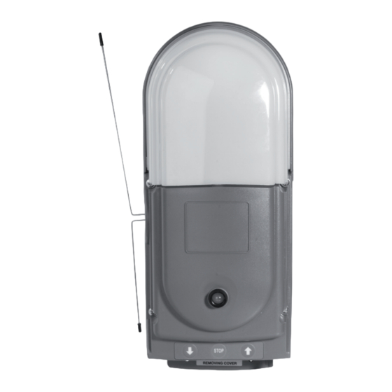
Aimant Aimant Magnet UNTE 4. Den FREEROLL RTS Empfänger an der Wand befestigen und verkabeln a. Wandmontage des Empfängers Den Empfänger vorsichtig aus der Verpackung nehmen. Die obere Abdeckung der integrierten Beleuchtung entfernen und hierfür auf beiden Seiten an der Basis drücken (siehe Pfeile nebenstehend).
Seite 51
Die zwei Antennen aus der Verpackung nehmen und sie an den Empfänger schrauben (Positionierung der An tennen und des Steckverbinders oben links Elektronikkarte, siehe nebenstehend). Stellen Sie sicher, dass sich die beiden Antennen nicht berühren, nicht überkreuzen und in die entgegengesetzte Richtung zeigen (eine nach oben, eine nach unten, beide p arallel zur Produktseite).
äußere Tasterfeld vorsichtig Klemmenleiste der Elektronikkarte anschließen, die wieder Gehäuse einbauen dabei nebenstehende Fotos berücksichtigen. Achtung! Wenn das äußere Tasterfeld in der falschen Richtung angeschlossen wird, funktionieren die externen Taster nicht korrekt. Hinweis:Die externe 3-poligen Klemmenleiste der Elektronikkarte angeschlossen. Hinweis: Achten Sie darauf, dass alle Switches des Blocks DIP 1 auf OFF stehen (unten) und dass die LED UNUNTERBROCHEN GRÜN leuchtet.
Andernfalls halten Sie das Tor an (STOP Taster) und schlagen im Diagnoseleitfaden auf Seite 58 nach. IHR FREEROLL RTS EMPFÄNGER IST JETZT BETRIEBSBEREIT. PROGRAMMIERUNG Achtung! Die mit dem Kit gelieferten Funkhandsender sind werksseitig auf dem linken Taster (Kanal 1) vorab konfiguriert.
FUNKTIONSTEST 1. Verwendung der Funkhandsender Äußere grüne LED blinkt Signalton Äußere orangefarbene LED leuchtet ununterbrochen Äußere rote LED blinkt Äußere orangefarbene LED leuchtet ununterbrochen Äußere grüne LED blinkt Signalton 2. Betrieb der Hindernisfunktion Bei Erkennung eines Übergewichts während des Öffnens wird das Tor angehalten (Antilift-Funktion). Achtung! Das Antriebsmoment muss auf das Gewicht und die Abmessungen des Garagenrolltors abgestimmt sein.
ANSCHLUSS VON PERIPHERIEGERÄTEN 1. Beschreibung der verschiedenen Peripheriegeräte Mark. Beschreibung Artikel-Nummer Warnleuchte orange, 230 V, mit integriertem Blinklicht 9011084 Fotozellen 9013647 1841028 Schlüsselschalter 1841036 Alarm-Buzzer 9014397 2. Elektroanschluss der verschiedenen Peripheriegeräte Achtung! elektrische Spannungsversorgung Empfängers Ausführung irgendwelcher Arbeiten an den Peripheriegeräten unterbrechen. Schlagen Sie im Hauptschaltplan auf Seite 62 nach.
Seite 56
2 Anschlussarten sind möglich: Standard (ohne Selbsttest) Mit Selbsttest Den Switch 1 des Blocks DIP 1 des Empfängers auf die Position ON stellen (aktive Fotozellen; siehe PARAMETRIERUNGEN Seite 57). Die einwandfreie Betriebsfähigkeit muss alle 6 Für die Überprüfung der Betriebsfähigkeit der Zellen Monate geprüft werden wird bei jeder Torbedienung ein Automatiktest durchgeführt.
PARAMETRIERUNGEN Achtung! Damit die neuen Parameter des Switch 1 von DIP1 und der anderen vier Switches von DIP 2 berücksichtigt und validiert werden, drücken Sie den RESET Taster an der Elektronikkarte. Parameter Dip Switch Standardbetriebsmodus RESET DIP 1 Fotozellen aktiv (immer verwenden, Switch 1 ON wenn Zellen mit Selbsttest) Switch 1 OFF...
DIAGNOSE 1. Anzeigen zum Betrieb des Systems Die Anzeigen zum Betrieb des Tors erfolgen über die äußere LED des Empfängers. Sie kann in drei Farben leuchten: ROT, GRÜN und ORANGE. Die Betriebsanzeigen werden unten im Detail aufgeführt. Torpositionen Äußere LED Status GRÜN UNUNTERBROCHEN Obere Endlage erreicht.
ROTES BLINKEN, anschließend 4 Mal BLINKEN ORANGE Das Tor hat seine Betriebszeit überschritten; Die Endlagen des Torantriebs neu einstellen. Das Öffnen bzw. Schließen hat länger als 60 sec gedauert, ohne dass eine Endlage erkannt wurde. Systemstatus Anzeigen der äußeren LED und Lösung Ursachen EINMALIGES SCHNELLES BLINKEN...
Seite 60
2. Den Kontaktleisten-Sender konfigurieren Die zu verwendenden Taster STOP und AB befinden sich an der Elektronikkarte a. Den Kontaktleisten-Sender löschen 1. Die Abdeckung des FREEROLL Empfängers entfernen angehaltenem folgende Schritte STOP durchführen. 2. Den Switch 4 von DIP 1 auf ON (oben) setzen. die äußere LED blinkt ORANGE.
2. Fijación de los imanes SUPERIOR e INFERIOR a la guía de la puerta ........66 3. Colocación de la puerta en posición....................66 4. Fijación del receptor FREEROLL RTS a la pared y cableado............67 5. Conexión y fijación del emisor de barra sensible ................67 6.
El producto FREEROLL debe instalarse en el interior del garaje con un sistema de mando de emergencia integrado (consulte las instrucciones de los motores RDO CSI). Somfy declara que este producto cumple los requisitos básicos y demás disposiciones pertinentes de la directiva 1999/5/CE.
2. Ámbito de aplicación Puertas de garaje enrollables para uso residencial. PUNTOS QUE DEBEN VERIFICARSE ANTES DE LA INSTALACIÓN 1. Controles preliminares No moje el dispositivo. No instale el FREEROLL en un lugar donde exista riesgo de caída de agua. La parte baja de la puerta debe incorporar una barra sensible de seguridad compatible con el sistema FREEROLL.
GUÍA DE INSTALACIÓN RÁPIDA Atención: del paso 1 al paso 3, es obligatorio utilizar un cable de ajuste para controlar la puerta de garaje enrollable. El receptor FREEROLL no está conectado a la corriente. 1. Ajuste de los finales de carrera del motor Ajuste los finales de carrera SUPERIOR e INFERIOR del motor RDO CSI con el cable de ajuste (no incluido).
. Vuelva a abrir la puerta completamente pulsando el botón . Pulse el botón de la tapa para cerrar la puerta completamente y probar el buen funcionamiento de la barra sensible simulando un obstáculo. EN ESTE ESTADIO DE LA INSTALACIÓN, EL RECEPTOR FREEROLL RTS ESTÁ LISTO PARA FUNCIONAR.
GUÍA DE INSTALACIÓN COMPLETA Atención: del paso 1 al paso 3, es obligatorio utilizar un cable de ajuste para controlar la puerta de garaje enrollable. El receptor FREEROLL no está conectado a la corriente. Las conexiones estándar para el montaje del motor a la derecha y la caja dentro son: Negro: cierre Azul: neutro...
2. Fijación de los imanes SUPERIOR e INFERIOR a la guía de la puerta. Atención: sitúe los imanes, el emisor de barra sensible y el receptor FREEROLL en el mismo lado de la puerta. Placa Plaque de Plaque de fijación del fixation de fixation de Sitúe la placa de fijación del emisor de barra sensible en la...
Aimant Aimant Imán INFERIOR 4. Fijación del receptor FREEROLL RTS a la pared y cableado a. Montaje en pared del receptor Saque el receptor del embalaje con mucho cuidado. Quite la cubierta de protección superior de la luz integrada presionando sobre su base por ambos lados (como se indica con las flechas de la imagen).
Seite 71
Saque las dos antenas del embalaje y atorníllelas al receptor (en la foto de la izquierda pueden verse las antenas y el conector en la parte superior izquierda de la tarjeta electrónica). Asegúrese de que las dos antenas no se tocan, de que no se cruzan y de qu e apuntan en direcciones opuestas (una hacia arriba y otra hacia abajo pero ambas paralelas a un lado del producto).
Conecte con precaución el cable plano de los botones de mando exteriores a la regleta de bornes de la tarjeta electrónica y vuelva a introducir el indicador luminoso en la tapa tal y como se indica en las fotos. Atención: si el cable plano de los botones exteriores se conecta en el sentido equivocado, los botones exteriores no funcionarán bien.
Si se activa la barra sensible, la puerta se para y se reabre parcialmente. Si esto no ocurre, detenga la puerta (botón STOP) y consulte la guía de diagnóstico página 77. EN ESTE ESTADIO DE LA INSTALACIÓN, EL RECEPTOR FREEROLL RTS ESTÁ LISTO PARA FUNCIONAR. PROGRAMACIÓN Atención: los mandos a distancia suministrados con el kit vienen preconfigurados de fábrica...
PRUEBA DE FUNCIONAMIENTO 1. Utilización de los mandos a distancia Indicador luminoso exterior verde intermitente Indicador luminoso exterior naranja fijo Indicador luminoso exterior rojo intermitente Indicador luminoso exterior naranja fijo Indicador luminoso exterior verde intermitente "BIP" 2. Funcionamiento de la detección de obstáculos La detección de un sobrepeso durante la apertura detiene la puerta (función anti-lift).
CONEXIÓN DE LOS PERIFÉRICOS 1. Descripción de los distintos periféricos Rep. Descripción Referencia Luz naranja 230 V con intermitente integrado 9011084 Células réflex 9013647 1841028 Interruptor con llave 1841036 Timbre de alarma 9014397 2. Conexión eléctrica de los distintos periféricos Atención: desconecte el receptor de la corriente eléctrica antes de realizar cualquier intervención en los periféricos.
Seite 76
Existe la posibilidad de hacer dos tipos de conexión: Estándar (sin auto-test) Con auto-test Ponga el interruptor 1 del bloque DIP 1 del receptor en la posición ON (Células réflex activas; ver CONFIGURACIÓN DE PARÁMETROS página 76). Hay que comprobar su buen funcionamiento Se realiza un test automático para comprobar el buen cada seis meses funcionamiento de las células cada vez que se acciona...
CONFIGURACIÓN DE PARÁMETROS Atención: para tener en cuenta y validar los nuevos RESET parámetros del interruptor 1 de DIP1 y de los cuatro interruptores de DIP 2, pulse el botón RESET de la tarjeta electrónica. Modo de funcionamiento Parámetros interruptor Dip estándar DIP 1 Células réflex activas (debe...
DIAGNÓSTICO 1. Indicaciones de funcionamiento del sistema Las indicaciones de funcionamiento de la puerta las facilita el indicador luminoso exterior del receptor. Puede ponerse de tres colores: ROJO, VERDE y NARANJA. Las indicaciones de funcionamiento se detallan a continuación. Posiciones de la puerta Indicador luminoso exterior Estado VERDE FIJO...
Estados del sistema Indicaciones del indicador luminoso Solución exterior y causas PARPADEO ÚNICO EN ROJO, VERDE Y NARANJA RÁPIDO Configure el emisor conectándolo al receptor Indica que se ha recibido una señal de un siguiendo el procedimiento descrito en la página 78. emisor que no está...
Seite 80
3. Pulse de manera sostenida el botón DESCENSO hasta que el indicador luminoso cambie a VERDE FIJO el indicador luminoso exterior pasara por la siguiente secuencia: ROJO INTERMITENTE – ROJO FIJO (5 seg.) – NARANJA FIJO (2 seg. – VERDE FIJO (2 seg.) el indicador luminoso exterior se pondrá...
CARACTERÍSTICAS TÉCNICAS Receptor FREEROLL RTS Alimentación 220-240 VCA/50 Hz Fusible T6.3AH 250V Potencia del motor 230 VCA 5A Índice de protección IP20 Temperatura ambiente de funcionamiento -20° C a +70 °C Frecuencia de radio RTS 433,42 MHz Entrada de seguridad Sí...
Seite 84
Somfy SAS dans un souci constant d’évolution et d’amélioration peut modifier le produit sans préavis. Photos non contractuelles. Somfy SAS in a constant concern of evolution and improvement may modify the product without prior notice. Non contractual pictures. Somfy SAS, capital 20.000.000 Euros, RCS Bonneville 303.970.230 01/2008...