Werbung
Verfügbare Sprachen
Verfügbare Sprachen
Quicklinks
I N S T R U C T I O N S
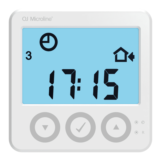
Waterline Room Controller/Sensor
67337A 03/17 (HKT)
English
Product programme
WLCT3-19 Wired room controller with clock
WLDT3-19 Wired room sensor with temperature adjustment, mode switch
(Auto, Day, Night, Frost Protection) and floor limit sensor
WLCT3-29 Wireless room controller with clock
WLDT3-29 Wireless room sensor with temperature adjustment, mode
switch (Auto, Day, Night, Frost Protection) and floor limit
sensor
Mounting of room controller/sensor (figs 1 and 2)
The unit is used for comfort temperature control in rooms. The unit should
be mounted on an internal wall approx. 1.4-1.7 metres above the floor in
such a way as to allow free air circulation around it. Draughts and direct
sunlight or other heat sources must be avoided.
Fig. 1 Removing the front cover
Fig. 2
WLCT3-19 / WLDT3-19: Wired room controllers/sensors – bus
connection (figs 3 and 4)
Only OJ units which are suitable for two-wire communication can be
used. Standard installation cable of minimum 2 x 0.25 mm² can be used.
Units can be connected in conventional star formation or in bus mode
(daisy chain). The master has four sets of terminals marked SENSOR/
CONTROLLER BUS that can be used for connecting the 2-core signal
cable from the unit.
• English
• Polski
• Norsk
• Deutsch
Any unit can be connected to any pair of terminals. The total length of
the 2-wire system can be up to 300 m with a maximum length of 100 m
between any two units. For further information see the table below.
Remember to connect + to + and – to – .
Table: Length of cable
Standard cable
≥0.25 mm²
≥0.50 mm²
≥0.75 mm²
*) Up to 300m if operation without backlight is acceptable.
WLCT3-29 / WLDT3-29: Wireless room controller/sensor
The plastic battery pull tab must not be removed until the master is in
learn mode. For further information, please refer to the section titled Room
Sensors - Wireless Setup in the Installation Manual. The unit uses 2 x AAA
alkaline batteries. A lifetime of 1-2 years is expected. The unit is equipped
with a low battery alarm which beeps every 5 minutes in case of low
battery. If a unit is defective, or communication to the unit is interrupted,
an alarm will be triggered on the master, and the room will be heated
constantly at 20% output for safety. The alarm can be overruled for the
next 24 hours.
NB: WLCT3-29 / WLDT3-29 can only be used along with a wireless receiver
type WLRC3-19 or WLRC2-19.
Fig. 3
Fig. 4
© 2017 OJ Electronics A/S
Max cable length from
Max cable length from
Master to Room Controller/
Master to Room Controller/
Sensor with display
Sensor without display
Up to 100 m *
Up to 300 m
Up to 200 m *
Up to 300 m
Up to 300 m *
Up to 300 m
1
Werbung

Verwandte Anleitungen für OJ Electronics WLCT3-19


Inhaltszusammenfassung für OJ Electronics WLCT3-19
- Seite 1 Fig. 3 Fig. 2 Fig. 4 WLCT3-19 / WLDT3-19: Wired room controllers/sensors – bus connection (figs 3 and 4) Only OJ units which are suitable for two-wire communication can be used. Standard installation cable of minimum 2 x 0.25 mm² can be used.
- Seite 2 CE marking on the master. The channel number can be set before power is connected OJ Electronics A/S hereby declares that the product conforms with the to the system. The channel set on the unit can be subsequently changed following Directives of the European Parliament and of the Council: if needed.
- Seite 3 Rys. 1 Zdejmowanie pokrywy przedniej Rys. 3 Rys. 4 Rys. 2 WLCT3-19 / WLDT3-19: Przewodowe termostaty programowalne/ Przyporządkowanie poszczególnych termostatów do siłowników przewodowe termostaty – podłączenie do magistrali (rys. 3 i 4) termicznych (rys. 5) Należy wykorzystywać wyłącznie urządzenia OJ dostosowane do Każdemu termostatowi można przypisać...
- Seite 4 Więcej informacji na temat konfiguracji systemu znajduje się Oznaczenie CE w instrukcji montażu, rozdział „Skrócony przewodnik”. OJ Electronics A/S niniejszym oświadcza, że produkt spełnia wymogi następujących dyrektyw Parlamentu Europejskiego i Rady: Rys. 5 • EMC – dyrektywa w sprawie kompatybilności elektromagnetycznej •...
- Seite 5 En enhet som er innstilt til CH1 vil aktivere den termiske aktuatoren som er koblet til utgang 1 på masteren. Kanalnummeret kan innstilles før det blir satt strøm på systemet. Kanalinnstillingen på enheten kan om WLCT3-19 / WLDT3-19: Kablet romregulatorer/følere – busstilkobling nødvendig endres etterpå. Hvis to romfølere er plassert i samme rom og (fig.
- Seite 6 Sertifiseringer Modus-Schalter (Automatik, Tag, Nacht, Frostschutz) und Fußbodenbegrenzungsfühler CE-merking WLCT3-29 Drahtloser Raumregler mit Uhr OJ Electronics A/S erklærer herved at produktet samsvarer med følgende WLDT3-29 Drahtloser Raumfühler mit Temperatureinstellung, Europaparlaments og -rådsdirektiver: Modus-Schalter (Automatik, Tag, Nacht, Frostschutz) und Fußbodenbegrenzungsfühler • EMC - elektromagnetisk kompatibilitet •...
- Seite 7 Abb. 4 Abb. 2 WLCT3-19 / WLDT3-19: Kabelgebundene Regler/Fühler – Konfiguration von welcher Raumregler/Fühler mit welchem Busanschluss (Abb. 3 und 4) thermischen Stellglied zu koppeln ist (Abb. 5) Nur OJ-Einheiten, die sich für Zweileiter-Kommunikation eignen, sind zu Jede Einheit kann dazu konfiguriert werden, einen bestimmten Ausgang benutzen.
-
Seite 8: Wartung
Stenager 13B · DK-6400 Sønderborg · Dänemark Tel: +45 73 12 13 14 · Fax +45 73 12 13 13 oj@ojelectronics.com · www.ojelectronics.com The OJ trademark is a registered trademark belonging to OJ Electronics A/S · © 2017 OJ Electronics A/S...