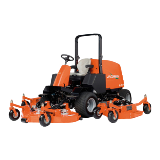
Jacobsen R-311T Handbuch
Sichelmäher mit überrollfaltbügel
Inhaltsverzeichnis
Verfügbare Sprachen
Verfügbare Sprachen
Quicklinks
Parts & Maintenance Manual
Ersatzteil- und Wartungshandbuch
R-311T
Rotary Mower with folding ROPS
™
R-311T
Sichelmäher mit Überrollfaltbügel
™
(ROPS)
69171 – Kubota
If incorrectly used, this machine can cause severe injury. Those who use
and maintain this machine should be trained in its proper use, warned of its
dangers and should read the entire manual before attempting to set up,
operate, adjust or service the machine
Wenn diese Maschine nicht ordnungsgemäß verwendet wird, können ernsthafte
Verletzungen verursacht werden. Personen, die diese Maschine verwenden und warten,
müssen in ihrer richtigen Verwendung ausgebildet sein, auf die Gefahren aufmerksam
gemacht worden sein und die Anleitung ganz gelesen haben, bevor sie versuchen,
die Maschine aufzustellen, zu bedienen, einzustellen oder zu warten.
DE
GB
United
Germany
Kingdom
V2403-M-T
®
WARNING
ACHTUNG
4227700-DE-Rev.A
6
5
9
1 1
1 6
1 3
1 5
7
8
1 8
1 7
1 - I N C L U D E S I T E M S 3 - 1 6
1 9
3
1 0
4
When Performance Matters.
™
Kapitel
Inhaltsverzeichnis
Fehlerbehebung

Verwandte Anleitungen für Jacobsen R-311T


Inhaltszusammenfassung für Jacobsen R-311T
- Seite 1 4227700-DE-Rev.A 1 - I N C L U D E S I T E M S 3 - 1 6 Parts & Maintenance Manual Ersatzteil- und Wartungshandbuch R-311T Rotary Mower with folding ROPS ™ R-311T Sichelmäher mit Überrollfaltbügel ™ (ROPS) 69171 –...
-
Seite 34: Empfohlener Lagerbestand
Jacobsen empfiehlt, dass Sie die Nummern zur leichteren Bezugnahme hier aufschreiben. Empfohlener Lagerbestand Damit Ihre Ausrüstung voll einsatzfähig und produktiv bleibt, empfiehlt Jacobsen, daß Sie einen Lagerbestand der häufiger verwendeten Wartungsteile erhalten. Wir haben die Teilnummern für zusätzliches Unterstützungsmaterial und Ausbildungshilfen hinzugefügt. - Seite 35 Inhalt SICHERHEIT WARTUNG Betriebssicherheit ..........4 Allgemeine Informationen ......... 18 Wichtige Hinweise zur Sicherheit ....... 5 Prüfen der Messer ........... 18 Schleifen der Messer ........19 TECHNISCHE DATEN Motor ..............20 Produktidentifizierung ......... 6 Motoröl ............. 20 Motor ..............6 Luftfilter ............
-
Seite 36: Sicherheit Betriebssicherheit
Zubehör und Zusatzgeräte zur ordnungsgemäßen und Vorschriften erfüllen. Beim Überqueren von oder sicheren Durchführung der Arbeit notwendig sind. Nur Betrieb in Nähe von Straßen auf den Verkehr achten. von Jacobsen genehmigtes Zubehör und Zusatzgeräte 19. Örtliche Bestimmungen können eine Altersgrenze für verwenden. den Bediener vorschreiben. -
Seite 37: Wichtige Hinweise Zur Sicherheit
Techniker vorgenommen werden. Wenn zusätzliche Informationen oder Dienstleistungen erforderlich sind, wenden Sie sich bitte an Ihren zugelassenen Vertragshändler von Jacobsen, der über die neuesten Methoden zum Instandhalten dieser Ausrüstung informiert wird und einen prompten und effizienten Dienst bereitstellen kann. de-5... -
Seite 38: Technische Daten
TECHNISCHE DATEN TECHNISCHE DATEN PRODUKTIDENTIFIZIERUNG ________________________________________________ ROPS heruntergeklappt . 69171......R-311T ® P.O. BOX 7708, Seriennummer ....Am Chassis des Traktors rechts CHARLOTTE, NC 28241, USA neben dem Fahrersitz befindet Jacobsen.com 1-800-848-1636 (US) sich am Traktorrahmen, neben 44.1 XXXX dem zentralen Hubarmhalter. -
Seite 39: Schneideeinheiten
Breite - Transportstellung..........2375 Breite - Mähstellung ............3530 ZUBEHÖR & BEGLEITLITERATUR____________________________________________ Eine komplette Aufstellung des Zubehörs und der Geräte von Jacobsen ist von Ihrem Händler erhältlich. WARNUNG Nur Originalersatzteile und -zubehör von Jacobsen verwenden. Das Mißachten dieses Hinweises kann zu Personenschäden und Beschädigungen am Gerät führen, wobei die Garantie ausgeschlossen ist. -
Seite 40: Konformitätserklärung
Valmistajan toiminimi ja täydellinen osoite ▪ Nom commercial et adresse complète du fabricant ▪ Firmenname und vollständige Adresse des Herstellers ▪ Jacobsen, A Textron Company Επωνυμία και ταχυδρομική διεύθυνση κατασκευαστή ▪ A gyártó üzleti neve és teljes címe ▪ Ragione sociale e indirizzo completo del fabbricante ▪... - Seite 41 Plaats en datum van de verklaring ▪ Deklaratsiooni väljastamise koht ja kuupäev ▪ Vakuutuksen paikka ja päivämäärä ▪ Lieu et date de la déclaration ▪ Jacobsen, A Textron Company Ort und Datum der Erklärung ▪ Τόπος και ημερομηνία δήλωσης ▪ A nyilatkozat kelte (hely és idő) ▪ Luogo e data della dichiarazione ▪...
-
Seite 42: Einstellungen
Techniker durchge- führt werden. Wenn es nicht möglich ist, die richtige Einstellung vorzunehmen, wenden Sie sich an einen Durchführung Einstellungen oder zugelassenen Vertragshändler von Jacobsen. Wartungsarbeiten die Vorrichtungen auf den Boden senken, alle Antriebe lösen, Feststellbremse 2. -
Seite 43: Bremspedal
EINSTELLUNGEN BREMSPEDAL ____________________________________________________________ Nach Austausch oder Wartung der Bremsen oder wenn das Pedalspiel zu groß wird, sind die Bremsen zu justieren. 1. Beim Einbau neuer Bremsbeläge sind die Beläge einzufahren, indem Mäher Mähgeschwindigkeit gefahren dabei Bremspedal mit leichtem Druck für etwa 5 Sekunden gedrückt wird. -
Seite 44: Tempomatschalter
EINSTELLUNGEN TEMPOMATSCHALTER ____________________________________________________ Wenn der Tempomat nicht abgeschaltet wird, wenn das Bremspedal gedrückt wird, muss der Tempomatschalter justiert werden. 1. Die Befestigungselemente (F) lösen. 2. Schalter (G) so justieren, dass die Kontakte geschlossen sind, wenn die Bremse gelöst ist, und dass sie sich öffnen, sobald das Bremspedal gedrückt wird. -
Seite 45: Hydroneutralstellung
(T) berührt und das Fahrpedal in Neutralstellung ist, und dass sie geschlossen sind, wenn das Pedal in Vorwärtsrichtung bewegt wird. 3. Schalterjustierung feststellen und die Funktion überprüfen. 4. Wenn die richtige Einstellung nicht vorgenommen werden kann, wenden Sie sich bitte an einen Jacobsen-Vertragshändler. Abb. 3I de-13... -
Seite 46: Vorspur
EINSTELLUNGEN 3.11 VORSPUR _____________________________________________________________________________ Die Vorspur sollte von X + 1,5 mm eingestellt werden. 1. Räder in gerade Fahrposition bringen. 2. Die zwei Gegenmuttern (U) der Spurstange lockern. 3. Spurstange einstellen und Gegenmuttern wieder festziehen. 4. Nach der Vorspureinstellung müssen die Anschlag- bolzen eventuell nachgestellt werden. -
Seite 47: Schnitthöhe
EINSTELLUNGEN 3.14 SCHNITTHÖHE ____________________________________________________________ Bevor die Schnitthöhe zum ersten Mal eingestellt wird, ist Abb. 3M zeigt den Aufkleber für die Höheneinstellung die Höhe der vorderen Schneideeinheit einzustellen. Zum der Stützräder. Verändern der Schnitthöhe die Schneidvorrichtungen nicht Spalte 1 - Schnitthöhe vom Traktor abnehmen. -
Seite 48: Einstellen Der Vorderen Schneideeinheit
EINSTELLUNGEN 3.15 EINSTELLEN DER VORDEREN SCHNEIDEEINHEIT _____________________________ 1. Bevor die Höhe der vorderen Schneideeinheit eingestellt werden kann, müssen die Reifen und Stützräder des Traktors korrekt aufgepumpt sein. Die Schnitthöhe hängt nämlich direkt vom Radius der Reifen ab. 2. Stellen Sie die Schnitthöhe an der vorderen Schneideeinheit auf 140 mm ein. -
Seite 49: Drehmomentdaten
Alle Drehmomente in diesen Tabellen sind ungefähre Wert und nur als Anhaltspunkt gedacht. Sie verwenden diese Drehmomente auf Ihr eigenes Risiko. Jacobsen übernimmt keine Verantwortung für Verluste, Ansprüche oder Schäden, die sich aus der Verwendung dieser Tabellen ergeben. Bei Verwendung eines Drehmomentwertes ist immer äußerste Vorsicht anzuwenden. -
Seite 50: Wartung
4. Die Abbildungen im Ersatzteilkatalog als Hinweis ordnungsgemäßen Einstellungen vorgenommen zum Demontieren und erneuten Zusammenbau der werden können, wenden Sie sich bitte an einen Komponenten verwenden. zugelassenen Vertragshändler von Jacobsen. 5. Alle gefährlichen Materialien (Batterien, Kraftstoff, 2. Die Ausrüstung regelmäßig überprüfen, einen... -
Seite 51: Schleifen Der Messer
WARTUNG SCHLEIFEN DER MESSER__________________________________________________ Zwischen Messer und Mähergehäuse einen Holzblock positionieren, damit sich das Messer nicht bewegt. Zum Entfernen des Messers die Halteschraube des Messers im Uhrzeigersinn drehen. 13 mm ACHTUNG An den Messer der Mähvorrichtung könnten sich scharfe Ränder bilden. Bei der Wartung und Handhabung immer vorsichtig vorgehen. -
Seite 52: Motor
Nutzlebensdauer des Motors haben. Wenn die Einspritzpumpe, Einspritzdüsen oder das HINWEIS Kraftstoffsystem gewartet werden müssen, wenden Sie sich bitte an einen zugelassenen Vertragshändler von Jacobsen. Der Traktor ist so konstruiert, daß er bei der Voreinstellung Reglers wirksamsten WICHTIG: Die normale Betriebstemperatur des funktioniert und schneidet. -
Seite 53: Luftfilter
WARTUNG LUFTFILTER ______________________________________________________________ Das Element zur Prüfung oder Reinigung nicht Das neue Element anbringen und sicherstellen, daß es entfernen. Ein unnötiges Entfernen des Filters erhöht das richtig sitzt. Risiko Eindringens Staub anderen Die Kappe wieder anbringen und sicherstellen, daß sie Fremdkörpern in den Motor. -
Seite 54: Batterie
WARTUNG BATTERIE _______________________________________________________________ Unbedingt sicherstellen, daß der Zündschalter auf OFF Die Polarität der Batterie prüfen, bevor die Batteriekabel (Aus) ist und der Zündschlüssel abgezogen ist, bevor man angeschlossen oder getrennt werden. an der Batterie arbeitet. Beim Anbringen der Batterie immer zuerst das ROTE positive (+) Batteriekabel und zuletzt das SCHWARZE WARNUNG negative (-) Erdungskabel anbringen. -
Seite 55: Hydraulikschläuche
Ölwechsel auch immer Hydraulikfilter Wenn das Öl abgelaufen ist, die Ölablaßschraube auswechseln. wieder anbringen und Hydrauliköl von Jacobsen einfüllen. Hydraulikölwechsel: Die Luft vom System ablassen. Den Bereich um den Öleinfüllverschluß herum reinigen, Alle Traktorfunktionen ca. 5 Minuten lang betreiben, um zu verhindern, daß Fremdkörper in das System um die Luft aus dem System abzulassen und das Öl... -
Seite 56: Hydraulikölfilter
Problem nicht berichtigt werden man daran arbeitet, immer den Zündschalter auf aus kann, wenden Sie sich an einen zugelassenen Ver- tragshändler von Jacobsen. stellen und das negative Batteriekabel (schwarz) entfernen. Den Kabelbaum und alle einzelnen Drähte von beweglichen Teilen fernhalten, um eine Beschädigung... -
Seite 57: Verfahren Zur Radmontage
Reinigungsmittel für Vinyl bzw. Gummi verwenden. Beschädigte Metalloberflächen reparieren Keinen Teil der Ausrüstung abwaschen, wenn sie heiß ist. Ausbesserungslack von Jacobsen verwenden. Zum optimalen Keine Hochdruckspritzvorrichtung oder Dampf verwenden. Schutz des Lacks die Ausrüstung mit Wachs einreiben. Kaltes Wasser und ein Autoreinigungsmittel verwenden. WARNUNG Zum Reinigen des Motors und der Kühlerlamellen... -
Seite 58: Kühler & Ölkühler
4.21 KÜHLER & ÖLKÜHLER_____________________________________________________ 7. Reinigen Sie die Rippen des Motor- und des ACHTUNG Ölkühlers mit Druckluft von bis zu 206 kPa. Hierzu können Sie bei Ihrem von Jacobsen autorisierten Händler eine spezielle Druckluftpistole (JAC 5098) Niemals versuchen, bei laufendem Motor den erwerben. -
Seite 59: Lagerung
WARTUNG 4.22 LAGERUNG ______________________________________________________________ Allgemeine Informationen Schneidvorrichtungen Den Traktor gründlich waschen und schmieren. Die Schneidvorrichtungen gründlich waschen, dann alle Beschädigtes und freigelegtes Metall reparieren und beschädigten und freigelegten Metallteile reparieren lackieren. oder lackieren. Den Traktor überprüfen, alle Schrauben anziehen, Alle Schmierstellen und Reibungspunkte schmieren. verschlissene oder beschädigte... -
Seite 60: Fehlersuche
FEHLERSUCHE ALLGEMEINE INFORMATIONEN _____________________________________________ Die folgende Fehlersuchtabelle listet die grundsätzlichen Probleme auf, die beim Anlassen und Betrieb entstehen können. Ausführlichere Informationen über das Hydraulik- und elektrische System erhalten Sie vom Vertragshändler von Jacobsen Händler an Ihrem Ort. Symptome Mögliche Ursachen Maßnahme... -
Seite 61: Wartung Und Schmierung
WARTUNG UND SCHMIERUNG WARTUNG UND SCHMIERUNG ALLGEMEINE INFORMATIONEN _____________________________________________ übertrifft. Schmiere einer kleinen ACHTUNG Handschmierpresse auftragen und langsam füllen, bis Schmiere herauszusickern beginnt. Keine Druckluftschmierpressen verwenden. Vor dem Reinigen, Einstellen oder Reparieren dieser Ausrüstung alle Antriebe lösen, die Vorrichtungen auf Regelmäßig eine kleine... -
Seite 62: Wartungsplan
Bedarf Zeigt den ersten Kundendienst für neue Maschinen an. Oder alle zwei Jahre (frühestes Datum gilt). III - Hydraulikflüssigkeit von Jacobsen verwenden: Fassungsvermögen: 19 Liter. Teil Nr. 2500548 Sichtbare Schläuche und Rohre auf Lecks oder (Gebinde aus 9,5-Liter-Flaschen) oder Teil Nr. 2500546 Ölflecken überprüfen. -
Seite 63: Anmerkungen
ANMERKUNGEN ANMERKUNGEN de-31... -
Seite 64: Ersatzteilkatalog
Brief beizulegen, Teile aufführt, Artikelnummer, den Farbcode und eine Beschreibung zurückgesandt werden. Das Porto muß im voraus des Teils wie in der Stückliste angegeben, aufführen. bezahlt werden. Die Verwendung von nicht durch Jacobsen zugelassenen Teilen macht die Garantie ungültig. de-32... -
Seite 70: Hood
R-311T Serial No. All 3.1 Hood 7 / 8 ®... -
Seite 72: Floorboard Platform
R-311T Serial No. All 4.1 Floorboard Platform 23 21... -
Seite 74: Utility Box
R-311T Serial No. All 5.1 Utility Box... -
Seite 76: Console Support
R-311T Serial No. All 6.1 Console Support... -
Seite 78: Seat And Seat Base
R-311T Serial No. All 7.1 Seat and Seat Base 4181865... -
Seite 80: Control Panel
R-311T Serial No. All 8.1 Control Panel Part of 8 Part of 11 Part of 34 Part of 19 Control Panel Decal... -
Seite 88: Brake Pedal
R-311T Serial No. All 13.1 Brake Pedal... -
Seite 90: Brake Caliper
R-311T Serial No. All 14.1 Brake Caliper... -
Seite 94: Steering Axle
R-311T Serial No. All 16.1 Steering Axle 22 23 21 22... -
Seite 102: Engine
R-311T Serial No. All 20.1 Engine... -
Seite 110: Hydraulic Tank Support
R-311T Serial No. All 25.1 Hydraulic Tank Support... -
Seite 112: Hydraulic Tank
R-311T Serial No. All 26.1 Hydraulic Tank... -
Seite 116: Traction Hydraulics
R-311T Serial No. All 28.1 Traction Hydraulics... -
Seite 136: Harness
R-311T Serial No. All 44.1 Harness... -
Seite 138: Front Lift Arms
R-311T Serial No. All 45.1 Front Lift Arms... -
Seite 144: Deck Mounting
R-311T Serial No. All 48.1 Deck Mounting... -
Seite 146: Front Deck
R-311T Serial No. All 49.1 Front Deck "X" "X" 5 / 7 8 / 10 38 13 24 25 NO STEP... -
Seite 150: Caster Wheels
R-311T Serial No. All 51.1 Caster Wheels 2 / 17 2 / 17 2 / 17 2 / 17... -
Seite 154: Lift Valve
R-311T Serial No. All 54.1 Lift Valve Part Number 1001802... - Seite 162 R-311T Serial No. All 60.1 Seat Part Number 4185878...
- Seite 171 R-311T Valve Right Motor 11.9 11.9 Left Steering Motor Valve 1500 PSI Control Valve DL SW 200 PSI Steering Cylinder 1500 PSI Backpressure Valve 50 PSI 300 PSI 300 PSI 300 PSI Lift Valve 0.0595 in. 0.0595 in. 0.0595 in.
-
Seite 172: O-Ring Chart
R-311T Serial No. All 64.1 O-Ring Chart O-Ring Face O-Ring Boss O-Ring Face O-Ring Face O-Ring Boss O-Ring Boss Seal Size Dash Size Seal Size Seal Size Dash Size Dash Size W-X-Y W-X-Y W-X-Y O-Ring Face O-Ring Not O-Ring Face... - Seite 175 INDEX 1000050...... 75 132647 ....... 77 3001371 ...... 49 326112 ...67 1000588...... 49 132864 ....... 92 3001372 ...... 49 326731 ......51 1000649....53 148049 ..... 119 3001373 ...... 49 337229 ......67 1000700....85 148081 ....... 77 3001374 ...... 49 338558 ......49 1000843......
- Seite 176 INDEX 351124 ....90 365959 ......81 400118 .... 101 403578 ..... 119 352604 ......77 365963 ......101 400120 ....65 403745 ....... 43 352726 ......57 365966 ......91 400124 ....50 403746 ....53 353914 ......61 365974 ......79 400128 ....... 50 403759 ..... 101 354065 ......94 365979 ......73...
- Seite 177 INDEX 4135582...... 83 4175121 ...... 79 4188780 ...... 37 4199520 ....124 4137099...... 69 4175664 ..... 43 4189000 ...... 39 4199521 ....124 4137138....107 4177920 ....51 4189001 ...... 39 4199600 ......71 4137139...... 63 4178004 ...... 51 4189002 ...... 39 4200143 ......79 4138341......
- Seite 178 INDEX 4203443.......79 4211460....35 4225664 ...... 59 444849 ....... 65 4203444.......79 4211620.....103 4227140 ....101 444850 ....... 51 4203520.......83 4211640.....105 4227180 ...... 45 445278 ....... 45 4203602.....133 4211760.......65 4227420 ...... 69 445642 ....... 61 4203603.....133 4212040.......43 4227440 ...... 69 445672 ....... 63 4203604.....133 4212423.......37 4227441 ......
- Seite 179 INDEX 450411 ....65 5000184 ....107 556417 ....... 79 450422 ....... 71 5000917 ...... 65 556419 ....... 79 450453 ....... 47 5000938 ...... 71 556450 ..... 128 452002 ..... 117 5001599 ....123 556845 ..... 124 452004 .. 37 5001603 ....
- Seite 182 World Class Quality, Performance and Support Equipment from Jacobsen is built to exacting standards ensured by ISO 9001 and ISO 14001 registration at all our manufacturing locations. A worldwide dealer network and factory trained technicians backed by Genuine Jacobsen Parts provide reliable, high-quality product support.