Herunterladen Inhalt Inhalt Diese Seite drucken
Inhaltsverzeichnis

Werbung

Verfügbare Sprachen

Verfügbare Sprachen

T E C H N O L O G Y F O R T H E W E L D E R ´ S W O R L D .
DE Betriebsanleitung / EN Operating instructions
FR Mode d´emploi / ES Instructivo de servicio
WH/VTS-Interlock/ABIROB W/ABIROB A/350GC/ABITIG-WH
Einstellvorrichtung
DE
EN
Alignment Jig
FR
Marbre de contrôle et de rectification
ES
Verificador / alineador de cuello
DIN EN
ISO 9001
www.binzel-abicor.com

Werbung

Inhaltsverzeichnis
loading

Inhaltszusammenfassung für Abicor Binzel ROBO VTS

  • Seite 1 T E C H N O L O G Y F O R T H E W E L D E R ´ S W O R L D . DE Betriebsanleitung / EN Operating instructions FR Mode d´emploi / ES Instructivo de servicio WH/VTS-Interlock/ABIROB W/ABIROB A/350GC/ABITIG-WH Einstellvorrichtung Alignment Jig...
  • Seite 2: Inhaltsverzeichnis

    Produktes erforderlich werden. Diese Änderungen werden jedoch in neuen Ausgaben berücksichtigt. Alle in der Betriebsanleitung genannten Handelsmarken und Schutzmarken sind Eigentum der jeweiligen Besitzer/Hersteller. Unsere aktuellen Produktdokumente, sowie alle Kontaktdaten der ABICOR BINZEL Ländervertretungen und Partner weltweit, finden Sie auf unserer Homepage www.binzel-abicor.com...
  • Seite 3: Identifikation

    Brennerhals bei gleicher Aufspannung geringfügig nachzurichten. Diese Betriebsanleitung beschreibt die Handhabung der Einstellvorrichtung. Handhabung und Beschreibung dieser Vorrichtung ist unabhängig von der Brennerausführung mit Ausnahme der Brennerhalsbefestigung. Die Einstellvorrichtung darf nur mit Original ABICOR BINZEL Ersatzteilen betrieben werden. 2 Sicherheit Beachten Sie das beiliegende Dokument Sicherheitshinweise.
  • Seite 4: Produktbeschreibung

    90 % bei 20 °C Tab. 2 Umgebungsbedingungen Transport und Lagerung HINWEIS • Da die Ausführung der Einstellvorrichtung abhängig von dem verwendeten Brennertyp ist, werden an dieser Stelle keine technischen Daten angegeben. 3.2 Abkürzungen ROBO VTS MIG/MAG-Schweißbrenner-System VTS-Interlock ® ABIROB MIG/MAG-Schweißbrenner-System W ® ABIROB Maschinengeführter Schweißbrenner luftgekühlt...
  • Seite 5: Verwendete Zeichen Und Symbole De

    Einstellvorrichtung 4 Lieferumfang 3.4 Verwendete Zeichen und Symbole In der Betriebsanleitung werden folgende Zeichen und Symbole verwendet: Symbol Beschreibung • Aufzählungssymbol für Handlungsanweisungen und Aufzählungen  Querverweissymbol verweist auf detaillierte, ergänzende oder weiterführende Informationen Handlungsschritt/e im Text, die der Reihenfolge nach durchzuführen sind 4 Lieferumfang •...
  • Seite 6: Einstellvorrichtung Aufstellen De

    5 Funktionsbeschreibung Einstellvorrichtung 5.1 Einstellvorrichtung aufstellen HINWEIS • Damit die Einstellvorrichtung verzugsfrei aufgeschraubt werden kann, muss der Aufstellungsort eine ebene Oberfläche haben, sollte trocken und frei von Verschmutzungen sein. Richthebel und Halterung Einspannkörper Führungskörper,kpl Brennerhals Grundplatte mit Prüfeinrichtung Abb. 1 Einstellvorrichtung aufstellen 1 Einstellvorrichtung befestigen.
  • Seite 7: Varianten

    Einspannkörper ROBO VTS ABITIG-WH 220W/400W 14 Richthülse ® ® Einspannkörper ABIROB Spannbügel 15 Adapter für ABIROB ® Einspannkörper ABIROB Brennerhals 16 Brennerhals ROBO VTS ® Einspannkörper WH ABITIG-WH 220W/400W 17 Brennerhals ABIROB 350GC Rändelschraube 10 Brennerhals WH ® 11 Brennerhals ABIROB ®...
  • Seite 8: Bedienung

    Tab. 6 Richthülsen Die Messhülsen sind brennerspezifisch und unterscheiden sich im Gewindezapfen: ® WH 455, WH 505/505 TS, ROBO VTS 0/500 TS, ABIROB W 500 TS WH 241/242, ROBO VTS 500/500 TS, ROBO VTS 290, ABITIG-WH WH 650/652 WH Kaltdraht/Laser ®...
  • Seite 9: Ausrichtung Überprüfen

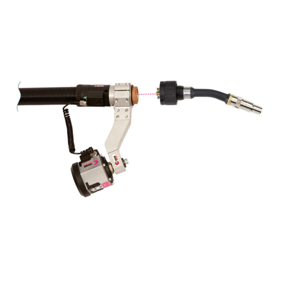
    Einstellvorrichtung 6 Bedienung 6.1.1 Ausrichtung überprüfen 1 Gasdüse abschrauben bzw. abziehen und weitere brennerspezifischen Ausrüstteile entfernen. Prüfdorn Messhülse Abb. 4 Ausrichtung prüfen 2 Messhülse (2) an Stelle der Stromdüse einschrauben. Der Biegewinkel ist in Ordnung, wenn der Prüfdorn (1) leichtgängig in die Bohrung der Messhülse (2) passt. 6.2 Biegewinkel justieren VORSICHT Sachschaden...
  • Seite 10: Wartung Und Reinigung

    7 Wartung und Reinigung Einstellvorrichtung 7 Wartung und Reinigung Regelmäßige und dauerhafte Wartung und Reinigung sind Voraussetzung für eine lange Lebensdauer und eine einwandfreie Funktion. WARNUNG Quetschgefahr Einziehen und zerquetschen der Hände durch laufende Räder. • Nicht in laufende Räder greifen. 7.1 Monatlich Eine monatliche Grundreinigung ist empfehlenswert, bei extremen Arbeitsbedingungen notwendig.
  • Seite 11: Betriebsmittel

    Betriebsmittelhersteller vorgegebenen Sicherheitsdatenblätter. Kontaminierte Reinigungswerkzeuge (Pinsel, Lappen usw.) müssen ebenfalls entsprechend den Angaben des Betriebsmittelherstellers entsorgt werden. 10.3 Verpackungen ABICOR BINZEL hat die Transportverpackung auf das Notwendigste reduziert. Bei der Auswahl der Verpackungsmaterialien wird auf eine mögliche Wiederverwertung geachtet. BAL.0022 • 2017-02-15...
  • Seite 12 All brand names and trademarks that appear in these operating instructions are the property of their respective owners/ manufacturers. Our latest product documents as well as all contact details for the ABICOR BINZEL national subsidiaries and partners worldwide can be found on our website at www.binzel-abicor.com...
  • Seite 13: Identification

    These operating instructions describe the handling of the alignment jig. Handling and description of this device are the same for all torches with exception of the torch neck fastening. The Alignment jig may only be operated using original ABICOR BINZEL spare parts. 2 Safety The enclosed safety instructions must be observed.
  • Seite 14: Classification Of The Warnings En

    3 Product description Alignment jig 2.4 Classification of the warnings The warnings used in the operating instructions are divided into four different levels and are shown prior to potentially dangerous work steps. Arranged in descending order of importance, they have the following meaning: DANGER Describes an imminent threatening danger.
  • Seite 15: Nameplate

    Alignment jig 4 Scope of delivery 3.2 Abbreviations ROBO VTS MIG/MAG welding torch system VTS-Interlock ® ABIROB MIG/MAG welding torch system W ® ABIROB Automatic welding torch, air-cooled ® ABIROB Automatic welding torch WH torches Neck change welding torch ABITIG-WH TIG neck change welding torch Tab.
  • Seite 16: Functional Description

    5 Functional Description Alignment jig Goods-in Use the delivery note to check that everything has been delivered. inspection Check the delivery for damage (visual inspection). In case of If the delivery has been damaged during transportation, contact the last carrier complaints immediately.
  • Seite 17 Alignment jig 5 Functional Description Adjusting lever and holder Clamping body Guide device,cmpl Torch neck Base plate with test device Abb. 1 Installing the alignment jig 1 Fasten the alignment jig. 2 Mount (5) the clamping device and the guide device according to the bending angle to be checked (3) on the base plate (4).
  • Seite 18: Versions

    ® ® Clamping device ABIROB Clamping bracket 15 Adapter for ABIROB ® Clamping device ABIROB Torch neck 16 Torch neck ROBO VTS ® Clamping device WH ABITIG-WH 220W/400W 17 Torch neck ABIROB 350GC Knurled screw 10 Torch neck WH ®...
  • Seite 19: Operation

    The measuring sleeves are torch-specific and have different threaded stems: ® WH 455, WH 505/505 TS, ROBO VTS 0/500 TS, W 500 TS ABIROB WH 241/242, ROBO VTS 500/500 TS, ROBO VTS 290, ABITIG-WH WH 650/652 WH cold wire / laser ® M10x1...
  • Seite 20: Check The Alignment

    6 Operation Alignment jig 6.1.1 Check the alignment. 1 Unscrew or pull out the gas nozzle and remove other torch-specific fittings. Test mandrel Measuring sleeve Abb. 4 Checking the Alignment 2 Screw in the measuring sleeve (2) at the position of the contact tip. The bending angle is correct if the test mandrel (1) fits easily into the bore of the measuring sleeve (2).
  • Seite 21: Maintenance And Cleaning

    Alignment jig 7 Maintenance and cleaning 7 Maintenance and cleaning Scheduled maintenance and cleaning is a prerequisite for a long life and a trouble-free operation. WARNING Danger of crushing Parts of the body can be crushed between the torch neck and the guide device when aligning the torch neck during normal operation.
  • Seite 22: Disassembly

    Contaminated cleaning tools (brushes, rags, etc.) must also be disposed of in accordance with the information provided by the consumables’ manufacturer. 10.3 Packaging ABICOR BINZEL has reduced the transport packaging to the necessary minimum. The ability to recycle packaging materials is always considered during their selection. EN - 12...
  • Seite 23 Alignment jig Notes Notes BAL.0022 • 2017-02-15 EN - 13...
  • Seite 24 Todas las marcas comerciales y marcas registradas mencionadas en este manual de instrucciones son propiedad del correspondiente propietario/fabricante. Para obtener la documentación actual sobre nuestros productos así como para conocer los datos de contacto de los representantes locales y socios de ABICOR BINZEL en todo el mundo, consulte nuestra página de inicio en www.binzel-abicor.com Identificación ES-3 Operación...
  • Seite 25: Identificación Es

    El Verificador/alineador de cuello debe utilizarse únicamente con piezas de recambio originales de ABICOR BINZEL. 2 Seguridad Observe también el documento adjunto “Instrucciones de seguridad”.
  • Seite 26: Descripción Del Producto Es

    AVISO • Ya que la versión del Verificador/alineador de cuello depende del tipo de antorcha utilizado, no se indican datos técnicos aquí. 3.2 Abreviaciones ROBO VTS MIG/MAG sistema de antorcha de soldadura VTS-Interlock ® ABIROB MIG/MAG Sistema de antorcha de soldadura refrigerada por agua ®...
  • Seite 27: Signos Y Símbolos Utilizados Es

    Verificador/alineador de cuello 4 Relación de material suministrado 3.4 Signos y símbolos utilizados En el manual de instrucciones se utilizan los siguientes signos y símbolos: Símbolo Descripción • Símbolo de enumeración para indicaciones de manejo y enumeraciones  El símbolo de remisión remite a información detallada, complementaria o adicional Paso/s de acción descritos en el texto a seguir en orden 4 Relación de material suministrado •...
  • Seite 28: Descripción Del Funcionamiento Es

    5 Descripción del funcionamiento Verificador/alineador de cuello 5 Descripción del funcionamiento Fijar el cuello al comprobar el ángulo de flexión correspondiente en un dispositivo de fijación. Después de una colisión es posible reajustar el cuello de antorcha mediante la palanca de ajuste. ¡ADVERTENCIA! Riesgo de aplastamiento Pueden aplastarse partes del cuerpo entre el cuerpo de antorcha y el dispositivo de guía al alinear el...
  • Seite 29: Versiones Es

    Dispositivo de fijación ROBO VTS Brazo de sujeción 15 Adaptador para ABIROB ® Dispositivo de fijación ABIROB Cuello de antorcha 16 Cuello de antorcha ROBO VTS ® Dispositivo de fijación ABIROB ABITIG-WH 220W/400W 17 Cuello de antorcha ® Dispositivo de fijación WH...
  • Seite 30: Operación

    Los casquillos de medición son específicos para cada antorcha y se distinguen por su vástago roscado. ® WH 455, WH 505/505 TS, ROBO VTS 0/500 TS, ABIROB W 500 TS WH 241/242, ROBO VTS 500/500 TS, ROBO VTS 290, ABITIG-WH WH 650/652 WH hilo frío / láser...
  • Seite 31: Controlar La Alineación

    Verificador/alineador de cuello 6 Operación 6.1.1 Controlar la alineación 1 Destornillar la tobera de gas o retirarla y retirar otros accesorios específicos de la antorcha. Espiga de control Casquillo de medición Fig. 4 Controlar la alineación 2 Introducir el casquillo de medición (2) en la posición del tubo/punta de contacto. El ángulo de flexión es correcto si la espiga de control (1) entra fácilmente en el orificio del casquillo de medición (2).
  • Seite 32: Mantenimiento Y Limpieza

    7 Mantenimiento y limpieza Verificador/alineador de cuello 7 Mantenimiento y limpieza El mantenimiento y la limpieza regulares son la condición previa para una larga vida útil y un funcionamiento perfecto. ¡ADVERTENCIA! Riesgo de aplastamiento Pueden aplastarse partes del cuerpo entre el cuerpo de antorcha y el dispositivo de guía al alinear el cuello durante el servicio normal.
  • Seite 33: Combustibles

    (cepillos, paños, etc.) también deben eliminarse según las indicaciones del fabricante de los combustibles. 10.3 Embalajes ABICOR BINZEL ha reducido el embalaje de transporte a un mínimo necesario. Al seleccionar los materiales de embalaje, se tiene en cuenta un posible reciclaje.
  • Seite 34 Toutes les marques déposées et marques commerciales contenues dans le présent mode d'emploi sont la propriété de leurs titulaires/fabricants respectifs. Vous trouverez nos documents actuels sur les produits, ainsi que l'ensemble des coordonnées des représentants et des partenaires d'ABICOR BINZEL dans le monde sur la page d'accueil www.binzel-abicor.com. Identification FR-3...
  • Seite 35: Identification

    à l’exception de la fixation du col de cygne. Le marbre de contrôle et de rectification ne doit être exploité qu'avec des pièces de rechange d’origine ABICOR BINZEL. 2 Sécurité...
  • Seite 36: Description Du Produit

    AVIS • La version du marbre de contrôle et de rectification dépendant du type de torche utilisée et des caractéristiques techniques ne seront pas indiquées ici. 3.2 Abréviations ROBO VTS Système de torche de soudage MIG/MAG VTS-Interlock ® ABIROB Système de torche de soudage MIG/MAG W ®...
  • Seite 37: Plaque Signalétique Fr

    Le marbre de contrôle et de rectification 4 Matériel fourni 3.3 Plaque signalétique Le marbre de contrôle et de rectification fait apparaître la référence sur la plaque de base. Pour tous renseignements complémentaires, les informations suivantes sont nécessaires: • Référence 3.4 Signes et symboles utilisés Dans le mode d'emploi, les signes et symboles suivants sont utilisés : Symbole Description...
  • Seite 38: Description Du Fonctionnement

    5 Description du fonctionnement Le marbre de contrôle et de rectification 5 Description du fonctionnement Le col de cygne à vérifier est serré dans un corps de fixation, suivant l’angle de flexion. Un levier d’ajustage permet d’ajuster légèrement le col de cygne à la suite d’une collision. AVERTISSEMENT Risque d’écrasement Lors de l’orientation du col de cygne dans le mode de fonctionnement normal, des parties du corps se...
  • Seite 39: Versions

    Organe de serrage ROBO VTS Etrier de blocage 15 Adaptateur, pour ABIROB ® Organe de serrage ABIROB Col de cygne 16 Col de cygne ROBO VTS ® Organe de serrage ABIROB ABITIG-WH 220W/400W 17 Col de cygne ® Organe de serrage WH...
  • Seite 40: Utilisation

    Les douilles de mesure sont spécifiques aux torches et se distinguent par la goupille filetée : ® WH 455, WH 505/505 TS, ROBO VTS 0/500 TS, ABIROB W 500 TS WH 241/242, ROBO VTS 500/500 TS, ROBO VTS 290, ABITIG-WH...
  • Seite 41: Vérification De L'orientation Fr

    Le marbre de contrôle et de rectification 6 Utilisation 6.1.1 Vérification de l’orientation 1 Dévisser ou retirer la buse-gaz et enlever d’autres pièces d’usure spécifiques à la torche. Tige de contrôle Douille de mesure Fig. 4 Vérification de l’orientation 2 Visser la douille de mesure (2) à l’endroit du tube-contact. L'angle de flexion est correct lorsque la tige de contrôle (1) entre légèrement dans l’alésage de la douille de mesure (2).
  • Seite 42: Entretien Et Nettoyage

    7 Entretien et nettoyage Le marbre de contrôle et de rectification 7 Entretien et nettoyage L'entretien et le nettoyage réguliers et permanents sont indispensables pour une longue durée de vie et un bon fonctionnement. AVERTISSEMENT Risque d'écrasement Risque d'écrasement des mains par l'engrenage en marche. •...
  • Seite 43: Produits Consommables Fr

    (pinceau, chiffon etc.) doivent être également éliminés selon les indications du fabricant des produits consommables. 10.3 Emballage ABICOR BINZEL a réduit l'emballage de transport au nécessaire. Lors du choix des matériaux d'emballage, veiller à ce que ces derniers soient recyclables. BAL.0022 • 2017-02-15...
  • Seite 44 T E C H N O L O G Y F O R T H E W E L D E R ´ S W O R L D . Alexander Binzel Schweisstechnik GmbH & Co.KG Postfach 10 01 53 • D–35331 Giessen Tel.: ++49 (0) 64 08 / 59–0 Fax:...

Diese Anleitung auch für:

Abirob wAbirob aAbirob gcWhAbitig-wh

Inhaltsverzeichnis