JUMO dTRANS T01 Ex Betriebsanleitung
Programmierbarer zweidraht-messumformer

Verwandte Anleitungen für JUMO dTRANS T01 Ex


Inhaltszusammenfassung für JUMO dTRANS T01 Ex
- Seite 1 JUMO dTRANS T01 Ex Programmierbarer Zweidraht-Messumformer Programmable 2-wire transmitter B 707015.0 Betriebsanleitung Operating Manual V2.00/DE-EN/00365407...
- Seite 2 Ex-Kennzeichnung II 1 G Ex ia IIC T6-T4 Ga Ex ia IIC T6-T4 Ga Besonderheiten Die Konformitätserklärung (Seite 14), die Baumusterprüfbe- scheinigung (Seite 20) und die IECEx-Konformitätsbeschei- nigung (Seite 29) sind zu beachten. Der Typ 707015/... entspricht dem Typ 956555/..
-
Seite 3: Zielgruppe / Normenkonformität
1 Zielgruppe / Normenkonformität Zielgruppe Beim JUMO dTRANS T01 Typ 707015/... handelt es sich um einen Zweidraht-Messumformer (Temperaturkopfmessumformer). An ihn können Widerstandsthermometer und Thermoelemente ange- schlossen werden. Der Einbau erfolgt vorzugsweise in Anschluss- köpfen Form B. Normenkonformität Die grundlegenden Sicherheits- und Gesundheitsanforderungen werden erfüllt durch Übereinstimmung mit:... -
Seite 4: Sicherheitshinweise
2 Sicherheitshinweise - Die Errichtung und der Betrieb des Temperaturkopfmessumfor- mers muss mit Hilfe dieser Betriebsanleitung und den für sie gülti- gen Regeln und Normen erfolgen. - Der Temperaturkopfmessumformer kann in Gerätegruppe „II“ Ka- tegorie „1 G“ (Zone 0), in „II 2 G“ (Zone 1) und in „II 3 G“ (Zone 2) betrieben werden. - Seite 5 2 Sicherheitshinweise - Die Umgebungstemperaturen dürfen die in der nachstehend auf- geführten Tabelle angegebenen Grenzwerte nicht überschreiten. - Der Temperaturkopfmessumformer ist so zu errichten, dass auch für die Anschlussteile ein Schutzgrad von mindestens IP20 ge- mäß EN 60529 erreicht wird. - Bei der Errichtung und dem Betrieb des Temperaturkopfmessum- formers ist darauf zu achten, dass keine elektrostatische Aufla- dung auftreten kann.
- Seite 6 3 Typenerklärung / -schilder JUMO dTRANS T01 (1) Grundausführung 707015 programmierbarer Zweidraht-Messumformer (2) Eingang (programmierbar) Werkseitig eingestellt (Pt100 DIN vl) Konfiguration nach Kundenangaben (3) Ausgang (eingeprägter Gleichstrom - programmierbar) Werkseitig eingestellt (4 … 20mA) Konfiguration nach Kundenangaben (20 … 4mA) (4) Fühlerbruch/-kurzschluss...
- Seite 7 3 Typenerklärung / -schilder Die nachfolgende abgebildeten Typenschilder befinden sich auf dem Gehäuse des Messumformers. oder Angabe von Messbereich und Sensor Der F-Nr. (Fabrikations-Nummer) kann das Produktionsdatum (Jahr/ Woche) entnommen werden. Es handelt sich hierbei um die Zeichen 12, 13, 14, 15. Beispiel: F-Nr.
-
Seite 8: Technische Daten
4 Technische Daten - Ex-Kennzeichnung: II 1 G Ex ia IIC T6-T4 Ga Ex ia IIC T6-T4 Ga - EG-Baumusterprüfbescheinigung: ZELM 99 ATEX 0018 X siehe Kapitel 2 „Sicherheitshinweise“ und Kapitel 9 „Baumusterprüfbescheinigung“ - Konformitätserklärung: siehe Kapitel 8 „Konformitätserklärung“ - IECEx-Konformitätsbescheinigung: siehe Kapitel 10 „IECEx-Konformitätsbescheinigung“... -
Seite 9: Installation
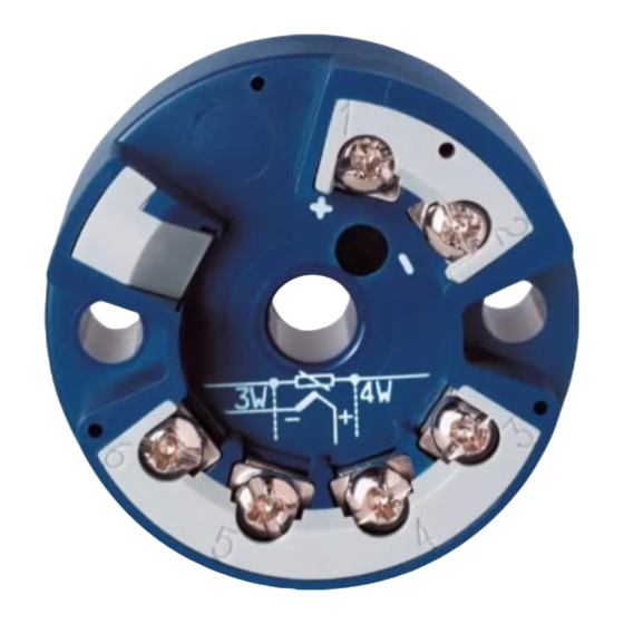
5 Installation Für das Errichten/Betreiben sind die Vorschriften gemäß ElexV und diese Betriebsanleitung maßgebend. maximale Umge- bungstemperatur (siehe Kapitel 2 „Sicherheitshinweise“) ist unbe- dingt einzuhalten. Abmessungen... - Seite 10 5 Installation Anschlussplan Anschluss für Anschlussbelegung Spannungs- – ---------------- - versorgung 22mA DC 8 ... 30V bzw. = Bürdenwiderstand Stromausgang = Spannungs- 4 ... 20mA versorgung Ex-Ausführung nur in Verbindung mit bescheinigtem Ex-Messumformer-Speisegerät! Analoge Eingänge ≤ Widerstands- 11Ω thermometer in Vierleiter- = Leitungswider- schaltung stand je Leiter...
- Seite 11 5 Installation Anschlussbeispiel mit Speisegerät/-trenner...
- Seite 12 6 Instandhaltung Die für die Wartung/Instandsetzung/Prüfung geltenden Bestimmun- gen sind einzuhalten. Im Rahmen der Wartung sind vor allem Teile zu prüfen, von denen die Zündschutzart abhängt. Eine Konfiguration des Messumformers über den Setup-Kreis darf niemals im explosionsgefährdeten Bereich erfolgen. Außerhalb des explosionsgefährdeten Bereiches darf der Anschluss aus sicher- heitstechnischen Gründen (Schutz der Ex-relevanten Bauelemente) nur zur kurzzeitigen Konfiguration erfolgen.
-
Seite 13: Setup-Schnittstelle Und Feinabgleich Setup-Schnittstelle
7 Setup-Schnittstelle und Feinabgleich Setup-Schnittstelle Die Setup-Schnittstelle dient zur Konfiguration des Messumformers mit Hilfe eines PC. Der Anschluss erfolgt über das PC-Interface mit TTL/RS232-Umsetzer und Adapter. Nach dem Programmieren ist die Verschlussklappe wieder zu schließen. Konfigurierbare Parameter: - TAG-Number (10 Zeichen) - Sensortyp - Anschlussart (2-/3-/4-Leiterschaltung) - externe oder interne Vergleichsstelle... -
Seite 14: Konformitätserklärung
8 Konformitätserklärung Document No. / Document n°. Manufacturer / Etabli par Address / Adresse Product / Produit Name / Nom Type / Type Data sheet no. / N° Document d'identification We hereby declare in sole responsibility that the designated product fulfills the requirements of the European Directives. Nous déclare sous notre seule responsabilité... - Seite 15 8 Konformitätserklärung Directive / Directive Name / Nom Reference / Référence Comment / Remarque Date of first application of the CE mark to the product / Date de 1ère application du sigle sur le produit Standards/Specifications applied / Normes/Spécifications appliquées Reference / Référence Edition / Édition Comment / Remarque...
- Seite 16 8 Konformitätserklärung Directive / Directive Name / Nom Reference / Référence Comment / Remarque Date of first application of the CE mark to the product / Date de 1ère application du sigle sur le produit Valid for Type / Valable pour le type EU type examination certificate / Certificat d'examen de type UE Reference / Référence Notified Body / Organisme notifié...
- Seite 17 8 Konformitätserklärung EU type examination certificate / Certificat d'examen de type UE Reference / Référence Notified Body / Organisme notifié Identification no. / N° d'identification Standards/Specifications applied / Normes/Spécifications appliquées Reference / Référence Edition / Édition Comment / Remarque Valid for Type / Valable pour le type Recognized quality assurance systems of production / Systèmes de qualité...
- Seite 18 8 Konformitätserklärung Directive / Directive Name / Nom Reference / Référence Comment / Remarque Date of first application of the CE mark to the product / Date de 1ère application du sigle sur le produit Standards/Specifications applied / Normes/Spécifications appliquées Reference / Référence Edition / Édition Comment / Remarque...
- Seite 19 8 Konformitätserklärung Issued by / Etabli par Place, date / Lieu, date Legally binding signatures / Signatures juridiquement valable...
-
Seite 20: Baumusterprüfbescheinigung
9 Baumusterprüfbescheinigung... - Seite 21 9 Baumusterprüfbescheinigung...
- Seite 22 9 Baumusterprüfbescheinigung...
- Seite 23 9 Baumusterprüfbescheinigung...
- Seite 24 9 Baumusterprüfbescheinigung...
- Seite 25 9 Baumusterprüfbescheinigung...
- Seite 26 9 Baumusterprüfbescheinigung...
- Seite 27 9 Baumusterprüfbescheinigung...
- Seite 28 9 Baumusterprüfbescheinigung...
-
Seite 29: Iecex-Konformitätsbescheinigung
10 IECEx-Konformitätsbescheinigung... - Seite 30 10 IECEx-Konformitätsbescheinigung...
- Seite 31 10 IECEx-Konformitätsbescheinigung...
- Seite 32 10 IECEx-Konformitätsbescheinigung...
- Seite 35 JUMO dTRANS T01 Ex Programmable 2-wire transmitter B 707015.0 Operating Manual V2.00/DE-EN...
-
Seite 36: Special Features
Ex marking II 1 G Ex ia IIC T6-T4 Ga Ex ia IIC T6-T4 Ga Special features Please note the Declaration of Conformity on page 14, of the Type Examination Certificate on page 20 and of the IECEx Certificate of Conformity on page 29. Type 707015/... -
Seite 37: Conformity With Standards
1 Application / Conformity with standards Application The JUMO dTRANS T01 Type 707015/... is a 2-wire head-mounted temperature transmitter which can be used with resistance ther- mometers and thermocouples. Preferably, it will be mounted into terminal heads Form B. Conformity with standards... -
Seite 38: Safety Notes
2 Safety notes - The head-mounted temperature transmitter must be set up and operated in accordance with this Operating Manual and the rele- vant regulations and standards. - The transmitter can be operated in device group II category 1 G (zone 0), in II 2 G (zone 1) and in II 3 G (zone 2). - Seite 39 2 Safety notes - The ambient temperatures must not exceed the limit values spec- ified in the table below. - The transmitter must be set up in such a way as to provide at least IP20 protection according to EN 60529, also for the con- necting parts.
-
Seite 40: Standard Accessories
3 Type designation/labels JUMO dTRANS T01 (1) Basic version 707015 programmable 2-wire transmitter (2) Input (programmable) factory-set (Pt100 DIN vl) custom configuration (3) Output (proportional DC current - programmable) factory-set (4 — 20mA) custom configuration (20 — 4mA) (4) Probe break/short-circuit... - Seite 41 3 Type designation/labels The labels shown below are attached to the transmitter housing. or specification of range and sensor The serial No. (F-Nr.) indicates the production date (year/week). The figures concerned are in position 12, 13, 14, 15. Example: F-Nr. 0136777101015030001 This shows that the transmitter was manufactured in 2015, week 3.
-
Seite 42: Technical Data
4 Technical data - Ex marking: II 1 G Ex ia IIC T6-T4 Ga Ex ia IIC T6-T4 Ga - EC type examination certificate: ZELM 99 ATEX 0018 X see Chapter 2 “Safety notes” and Chapter 9 “Type Examination Certificate” - Declaration of Conformity: see Chapter 8 “Declaration of Conformity”... - Seite 43 5 Installation The regulations according to ElexV and this Operating Manual apply when setting up and operating the transmitter. It is imperative to ob- serve the maximum ambient temperature (see Chapter 2 “Safety notes”). Dimensions...
-
Seite 44: Connection Diagram
5 Installation Connection diagram Connection for Terminals Supply – ---------------- - 8 — 30V DC 22mA current output = burden resistance 4 — 20mA = supply Ex version only in combination with a certified Ex transmitter supply unit! Analog inputs ≤... - Seite 45 5 Installation Example of connection with supply unit/isolator...
-
Seite 46: Maintenance
6 Maintenance The appropriate regulations concerning maintenance, repair and testing must be observed. In particular, all parts on which explosion protection depends must be checked during maintenance. The transmitter must never be configured inside the hazardous area via the setup circuit. For safety reasons (protection of Ex-relevant components), the connection outside the hazardous area may only be made for the purpose of brief configuration. - Seite 47 7 Setup interface and fine calibration Setup interface The setup interface is available for configuring the transmitter from a PC. The connection is via the PC interface with a TTL/RS232 con- verter and adapter. The cover flap must be closed after programming. Configurable parameters: - tag number (10 characters) - sensor type...
-
Seite 48: Declaration Of Conformity
8 Declaration of Conformity Document No. / Document n°. Manufacturer / Etabli par Address / Adresse Product / Produit Name / Nom Type / Type Data sheet no. / N° Document d'identification We hereby declare in sole responsibility that the designated product fulfills the requirements of the European Directives. Nous déclare sous notre seule responsabilité... - Seite 49 8 Declaration of Conformity Directive / Directive Name / Nom Reference / Référence Comment / Remarque Date of first application of the CE mark to the product / Date de 1ère application du sigle sur le produit Standards/Specifications applied / Normes/Spécifications appliquées Reference / Référence Edition / Édition Comment / Remarque...
- Seite 50 8 Declaration of Conformity Directive / Directive Name / Nom Reference / Référence Comment / Remarque Date of first application of the CE mark to the product / Date de 1ère application du sigle sur le produit Valid for Type / Valable pour le type EU type examination certificate / Certificat d'examen de type UE Reference / Référence Notified Body / Organisme notifié...
- Seite 51 8 Declaration of Conformity EU type examination certificate / Certificat d'examen de type UE Reference / Référence Notified Body / Organisme notifié Identification no. / N° d'identification Standards/Specifications applied / Normes/Spécifications appliquées Reference / Référence Edition / Édition Comment / Remarque Valid for Type / Valable pour le type Recognized quality assurance systems of production / Systèmes de qualité...
- Seite 52 8 Declaration of Conformity Directive / Directive Name / Nom Reference / Référence Comment / Remarque Date of first application of the CE mark to the product / Date de 1ère application du sigle sur le produit Standards/Specifications applied / Normes/Spécifications appliquées Reference / Référence Edition / Édition Comment / Remarque...
- Seite 53 8 Declaration of Conformity Issued by / Etabli par Place, date / Lieu, date Legally binding signatures / Signatures juridiquement valable...
-
Seite 54: Type Examination Certificate
9 Type Examination Certificate... - Seite 55 9 Type Examination Certificate...
- Seite 56 9 Type Examination Certificate...
- Seite 57 9 Type Examination Certificate...
- Seite 58 9 Type Examination Certificate...
- Seite 59 9 Type Examination Certificate...
- Seite 60 9 Type Examination Certificate...
- Seite 61 9 Type Examination Certificate...
- Seite 62 9 Type Examination Certificate...
-
Seite 63: Iecex Certificate Of Conformity
10 IECEx Certificate of Conformity... - Seite 64 10 IECEx Certificate of Conformity...
- Seite 65 10 IECEx Certificate of Conformity...
- Seite 66 10 IECEx Certificate of Conformity...
- Seite 68 JUMO GmbH & Co. KG JUMO Instrument Co. Ltd. JUMO Process Control, Inc. Street address: JUMO House 6733 Myers Road Moritz-Juchheim-Straße 1 Temple Bank, Riverway East Syracuse, NY 13057, USA 36039 Fulda, Germany Harlow, Essex, CM20 2DY, UK Delivery address:...