Bender ISOMETER IR426-D47 Handbuch
Isolationsüberwachungsgerät
Inhaltsverzeichnis
Quicklinks
Handbuch/Manual
ISOMETER® IR426-D47
Isolationsüberwachungsgerät
Bestimmungsgemäße Verwendung
®
Das ISOMETER
IR426-D47 überwacht den Isolationswiderstand
R
eines ungeerdeten AC/DC-Steuerstromkreises (IT-System) von
F
AC 0...132 V bzw. DC 0...132 V. Die zulässige Netzableitkapazität
C
max beträgt 20 μF.
e
Typische Anwendung ist die Überwachung AC- oder DC-gespeis-
ter OP-Leuchten-Kreise.
Sicherheitshinweise allgemein
Alle zum Einbau, zur Inbetriebnahme und zum
laufenden Betrieb eines Gerätes oder Systems er-
forderlichen Arbeiten sind durch geeignetes
Fachpersonal auszuführen.
Lebensgefahr durch Stromschlag!
Bei Berühren von unter Spannung stehenden An-
lagenteilen besteht die Gefahr
• eines elektrischen Schlages,
• von Sachschäden an der elektrischen Anlage,
• der Zerstörung des Gerätes.
GEFAHR
Stellen Sie vor Einbau des Gerätes und vor Arbei-
ten an den Anschlüssen des Gerätes sicher, dass
die Anlage spannungsfrei ist. Beachten Sie die Re-
geln für das Arbeiten an elektrischen Anlagen.
Bestandteil der Gerätedokumentation sind neben diesem Hand-
buch die „Sicherheitshinweise für Bender-Produkte".
Sicherheitshinweise gerätespezifisch
Gefahr vor Sachschaden durch
unsachgemäße Installation!
Die Anlage kann Schaden nehmen, wenn Sie in
einem leitend verbundenen System mehr als ein
Isolationsüberwachungsgerät anschließen. Sind
mehrere Geräte angeschlossen, funktioniert das
VORSICHT
Gerät nicht und meldet keine Isolationsfehler.
Schließen Sie in jedem leitend verbundenen
System nur ein Isolationsüberwachungsgerät an.
Trennung vom IT-System beachten!
Vor Isolations- und Spannungsprüfungen an der
Anlage muss das Isolationsüberwachungsgerät für
die Dauer der Prüfung vom IT-System getrennt
VORSICHT
sein. Andernfalls kann das Gerät Schaden nehmen.
Bei einer Alarmmeldung des ISOMETER®s sollte der
Isolationsfehler schnellstmöglich beseitigt werden.
Die Meldung des ISOMETER®s muss auch dann
akustisch und/oder optisch wahrnehmbar sein,
wenn das Gerät innerhalb eines Schaltschrankes
installiert ist.
Funktionsbeschreibung
®
Das ISOMETER
IR426-D47 erzeugt eine pulsförmige Messspan-
nung. Diese wird über die Klemmen L1/L2 und KE/E dem zu über-
IR426-D47_D00040_03_M_DEEN/07.2017
Insulation monitoring device
Intended use
®
The IR426-D47 ISOMETER
monitors the insulation resistance of
an unearthed AC or DC control circuit (IT system) of AC 0...132 V
respectively DC 0...132 V. The maximum permissible system
leakage capacitance C
is 20 μF.
e
A typical application is the monitoring of AC/DC supplied operat-
ing theatre lighting circuits.
Safety instructions
Only qualified personnel are permitted to carry
out the work necessary to install, commission and
run a device or system.
Risk of electrocution due to electric shock!
Touching live parts of the system carries the risk of:
• An electric shock
• Damage to the electrical installation
• Destruction of the device
Before installing and connecting the device,
DANGER
make sure that the installation has been de-en-
ergised. Observe the rules for working on electri-
cal installations.
Part of the device documentation in addition to this manual is the
enclosed "Safety instructions for Bender products".
Device-specific safety information
Risk of property damage due to
unprofessional installation!
If more than one insulation monitoring device is
connected to a conductively connected system,
the system can be damaged. If several devices are
connected, the device does not function and does
CAUTION
not signal insulation faults. Make sure that only
one insulation monitoring device is connected in
each conductively connected system.
Ensure disconnection from the IT system!
When insulation or voltage tests are to be carried
out, the device shall be isolated from the system
for the test period. Otherwise the device may be
CAUTION
damaged.
In the event of an alarm message, the insulation
fault should be eliminated as quickly as possible.
If the ISOMETER® is installed inside a control cabi-
net, the insulation fault message must be audible
and/or visible to attract attention.
Function
®
The IR426-D47 ISOMETER
generates a pulsating measuring volt-
age which is superimposed on the IT system being monitored via
1
Inhaltsverzeichnis

Verwandte Anleitungen für Bender ISOMETER IR426-D47


Inhaltszusammenfassung für Bender ISOMETER IR426-D47
- Seite 1 Arbeiten an elektrischen Anlagen. Bestandteil der Gerätedokumentation sind neben diesem Hand- Part of the device documentation in addition to this manual is the buch die „Sicherheitshinweise für Bender-Produkte“. enclosed "Safety instructions for Bender products". Sicherheitshinweise gerätespezifisch Device-specific safety information Gefahr vor Sachschaden durch Risk of property damage due to unsachgemäße Installation!
-
Seite 2: Montage Und Anschluss
ISOMETER® IR426-D47 wachenden IT-System überlagert. Ohmsche Isolationsfehler the terminals L1/L2 and KE/earth. Ohmic insulation faults close zwischen IT-System und Erde schließen den Messkreis. Der aktu- the measuring circuit between the IT system and earth. The cur- elle gemessene Isolationswiderstand wird auf dem Display des rently measured insulation resistance is shown on the display of Geräts angezeigt. -
Seite 3: Wiring Diagram
ISOMETER® IR426-D47 Schraub-Befestigung: Screw fixing: Bringen Sie die rückseitigen Montageclips (2. Montage- Use a tool to move the rear mounting clip (another mount- clip erforderlich, siehe Bestellinformation) mittels Werk- ing clip required, see ordering details) into a position that zeug in eine über das Gehäuse hinaus ragende Position. it projects beyond the enclosure. -
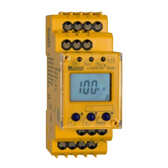
Seite 4: Anzeige- Und Bedienelemente
ISOMETER® IR426-D47 Anzeige- und Bedienelemente Indicating and operating elements Ele- Genutzte Elemente des Displays/ Ele- Funktion Function ment Display segments in use ment Ansprechwerte R R1, R2 Response values R R1, R2 Alarm-Relais K1, K2 1, 2 Alarm relay K1, K2 1, 2 Anlaufverzögerung t, Starting delay t,... -
Seite 5: Factory Setting
ISOMETER® IR426-D47 Werkseinstellung Factory setting Ansprechwert 1/2 (AL 1/2): 50 kΩ / 50 kΩ Response value 1/2 (AL 1/2) 50 kΩ / 50 kΩ Arbeitsweise K1/K2: Operating mode K1/K2: Ruhestrom-Betrieb N/C (n.c.) N/C operation (n.c.) Fehlerspeicher: deaktiviert (OFF) Fault memory: deactivated (OFF) Anlaufverzögerung: Starting delay:... -
Seite 6: Verzögerungszeiten Einstellen
ISOMETER® IR426-D47 Setting the time delay Verzögerungszeiten einstellen Use this segment to enter the response delay t (0…99 s) and Hiermit können Sie eine Ansprechverzögerung t (0…99 s) so- the starting delay t (0…10 s). wie eine Anlaufverzögerung t (0…10 s) vorgeben Werkseinstellung herstellen und Passwort-Schutz Reset to factory setting and password protection Use this menu to activate the password protection, to change the... -
Seite 7: Technische Daten Ir426-D47
ISOMETER® IR426-D47 Führen Sie eine Funktionsprüfung mittels eines It is recommended to carry out a functional test echten Isolationsfehlers R gegen Erde durch, using a genuine earth fault, e.g. via a suitable ggf. über einen dafür geeigneten Widerstand. resistance! Technische Daten IR426-D47 Technical data IR426-D47 ( )* = Werkseinstellung ( )* = factory setting... - Seite 8 Genehmigung des Herausgebers. only with permission of the publisher. Änderungen vorbehalten! Subject to change! © © Bender GmbH & Co. KG Bender GmbH & Co. KG Bender GmbH & Co. KG Tel.: +49 6401 807-0 E-Mail: info@bender.de •...