Herunterladen Inhalt Inhalt Diese Seite drucken
Inhaltsverzeichnis

Werbung

Verfügbare Sprachen

Verfügbare Sprachen

Werbung

Inhaltsverzeichnis
loading

Inhaltszusammenfassung für Futurelight Vojager

  • Seite 2 Weitere Produkte aus dem FUTURELIGHT-Sortiment: Further products from the FUTURELIGHT-range: Autres produits de l’assortiment de FUTURELIGHT: Artikelbeschreibung Art. nr. Article designation Art. no. Description d’article No. d’art. FUTURELIGHT LICHTEFFEKTE FUTURELIGHT LIGHTING EFFECTS FUTURELIGHT EFFETS LUMINEUX FUTURELIGHT RT-150, DMX Zylinder,für EFR 51830500 FUTURELIGHT FX-150, DMX Flower, für EFR 51830550...
  • Seite 3: Inhaltsverzeichnis

    Inhaltsverzeichnis: 1. Sicherheit..........................2 1.1 Sicherheitshinweise ........................2 1.2 Bestimmungsgemäße Verwendung..................3 2. Einführung........................3 2.1 Allgemeine Abmessungen und Beschreibung der Teile............3 2.2 Einsetzen der Lampe........................ 4 3. Installation ........................4 3.1 Allgemeine Hinweise ........................ 4 3.2 Anschluß ans Netz ........................5 3.3 Anschluß...
  • Seite 4: Sicherheit

    Bedienungsanleitung VOYAGER 575 HMI LESEN SIE VOR DER ERSTEN INBETRIEBNAHME ZUR EIGENEN SICHERHEIT DIESE BEDIENUNGSANLEITUNG SORGFÄLTIG DURCH ! 1. Sicherheit 1.1 Sicherheitshinweise Alle Personen, die mit der Aufstellung, Inbetriebnahme, Bedienung, Wartung und Instandhaltung dieses Gerätes zu tun haben, müssen - entsprechend qualifiziert sein - diese Betriebsanleitung genau beachten Dieses Gerät hat das Werk in sicherheitstechnisch einwandfreiem Zustand verlassen.
  • Seite 5: Bestimmungsgemäße Verwendung

    1.2 Bestimmungsgemäße Verwendung Dieser Projektor wurde nur zum Gebrauch in geschlossenen Räumen konzipiert. Vermeiden Sie Erschütterungen und jegliche Gewaltanwendung bei der Installation oder Inbetriebnahme des Gerätes. Eigenmächtige Umbauten und Veränderungen des Projektors sind aus Sicherheitsgründen verboten! Sie können den Projektor überall gemäß den Bestimmungen installieren, achten Sie dabei jedoch auf eine stabile Befestigung und auf eventuell frei herumliegende Kabel.
  • Seite 6: Einsetzen Der Lampe

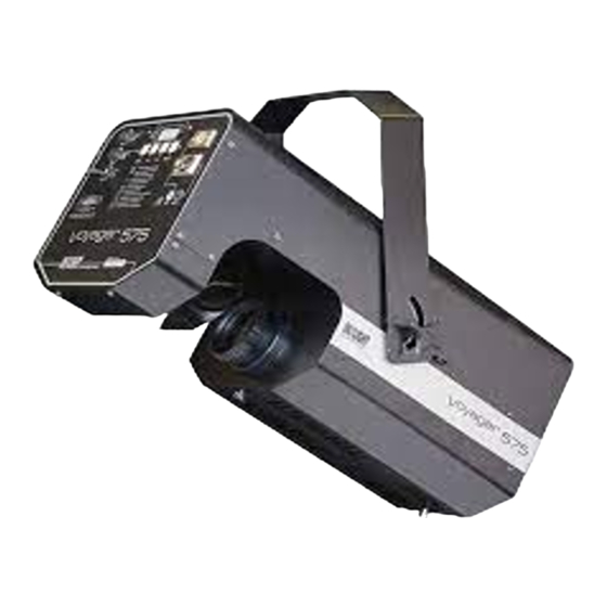
    (8) DIP Schalter zur Projektorwahl (9) DMX Eingang (10) DMX Ausgang (11) Netzstecker (12) Sicherungshalter (13) Erdungsschraube (14) DMX Kontrollampe 2. 2 Einsetzen der Lampe Zum Einsetzen der Lampe (HMI 575 zweiseitig gesockelt) öffnen Sie das Gehäuse indem Sie die (6) Gehäuseschrauben an der Seite lösen.
  • Seite 7: Anschluß Ans Netz

    Achten Sie darauf, daß das Gerät sicher befestigt wird. Vergewissern Sie sich, daß die Verankerung stabil ist. Den Projektor (in der gewünschten Position) an der dafür vorgesehenen Bohrung im Bügel des Gehäuses befestigen. Die Bohrung hat einen Durchmesser von 8mm. Sichern Sie den Projektor immer mit einem Sicherheitsfangseil.
  • Seite 8: Bedienung

    4. Bedienung KANAL FUNKTION 4.1 Funktionen der Steuerkanäle TILT FARBRAD GOBO ROTATION I. Steuerkanal 1 - Pan IRIS DIMMER/STROBE SPEZIALEFFEKTE Wenn Sie das Potentiometer verschieben, bewegen Sie den Spiegel horizontal (PAN). Allmähliches Einstellen des Spiegels bei langsamen Schieben des Potentiometers (0-255; 128 = Mitte). Der Spiegel kann an jeder gewünschten Einstellung angehalten werden.
  • Seite 9: Steuerkanal 4 - Gobos

    IV. Steuerkanal 4 - Gobos 0-31 Vollkreis 32-63 Gobo 1 rotierend 64-95 Gobo 1 statisch 96-127 Gobo 2 rotierend 128-159 Gobo 2 statisch 160-191 Gobo 3 rotierend 192-223 Gobo 3 statisch 224-255 Gobo 4 rotierend V. Steuerkanal 5 - Rotation Statisch 1-127 Drehung auf 270°...
  • Seite 10: Steuerkanal 7 - Dimmer/Strobe

    VII. Steuerkanal 7 - Dimmer/Stroboskospeffekt Shutter geschlossen 1-129 Dimmer 130-140 Offen 141-150 Shutter geschlossen 151-240 Strobe: 1-6 Blitze pro Sekunde 241-245 Komplett geöffnet 246-248 Blackout (Reset) 249-255 Offen VIII. Steuerkanal 8 - Spezialeffekte: 0-49 Offen 50-99 Korrekturfilter 5600° K 100-149 Korrekturfilter 3200°...
  • Seite 11: Technische Daten

    Jeder Projektor belegt 8 Steuerkanäle. Damit die Steuersignale richtig an jeden Projektor adressiert werden, müssen die Projektoren kodiert werden. Die Kodierung muß an jedem Projektor einzeln durchgeführt werden, indem man die DIP Schalter entsprechend der obenstehenden Tabelle einstellt. Durch den Test-Schalter wird das Selbsttestprogramm aktiviert.
  • Seite 12: Wartung Und Reinigung

    6. Wartung und Reinigung Es ist unbedingt erforderlich, daß Sie den Projektor in regelmäßigen Abständen reinigen, da der sich ablagernde Schmutz und Staub sowie Nebelfluidrückstände die Leuchtkraft des Gerätes erheblich beeinträchtigen. Falls Sie das Gerät nicht reinigen, wird außerdem die Lebensdauer Ihres Gerätes beträchtlich verkürzt. Verwenden Sie zur Reinigung ein fusselfreies, mit gutem Glasreiniger angefeuchtetes Tuch.
  • Seite 13 Table of contents: 1. Safety ..........................12 1.1 Safety instructions ........................12 1.2 Operating determinations ......................12 2. Introduction ........................13 2.1 Measurements and description of components ................. 13 2.2 Fitting the lamp.......................... 13 3. Installation ........................14 3.1 General Instructions ........................14 3.2 Connection to the mains......................
  • Seite 14: Safety

    User Manual VOYAGER 575 HMI FOR YOUR OWN SAFETY, PLEASE READ THIS USER MANUAL CAREFULLY BEFORE YOU INITIAL START-UP! 1. Safety 1.1 Safety instructions This device has left our premises in absolutely perfect conditon. In order to maintain this condition and to ensure a safe operation, it is absolutely necessary for the user to follow the safety instructions and warning notes written in this manual.
  • Seite 15: Introduction

    2. Introduction Thank you for having chosen a FUTURELIGHT VOYAGER 575 HMI. You acquired a versatile, powerful and intelligent light effect. Unpack your FUTURELIGHT VOYAGER 575 HMI and make sure that there are no damages caused by transportation. Should there be any, please consult your local dealer and do not take the device into operation.
  • Seite 16: Installation

    Do not install a lamp with a higher wattage! A lamp like this generates temperatures the device is not de- signed for. Damages caused by non-observance are not subject to warranty. Insert the lamp now. Do not touch the glass-bulb bare-handed during the installation! Please follow the lamp manufacturer's notes! Before you close the housing again, make sure that the lamp is...
  • Seite 17: Dmx 512 Connection / Connection Between Projectors

    The electric connection must be carried out by a qualified employee. 3.3. DMX 512 connection / Connection between projectors Connect the controller to the projector or one projector to another only by a stereo shielded cable and ¼ "-stereo jacks. Caution: At the last scanner, the DMX-cable has to be terminated with a 120 Ω...
  • Seite 18: Channel 3 - Colours

    Channel 3 - Colours Linear colour change following the movement of the slider. In this way you can stop the colour wheel in any position - also between two colours creating double-coloured beams. Between 5 and 10 (50 to 100% or 128 to 255) the colour wheel rotates continuously - the so-called "Rainbow"...
  • Seite 19: Channel 6 - Iris

    VI. Channel 6 - Iris 0-255 Iris width steplessly variable VII. Channel 7 - Dimmer/Stroboscopeffect Shutter closed 1-129 Dimmer 130-140 Open 141-150 Shutter closed 151-240 Strobe: 1-6 flashlights per second 241-245 Completely open 246-248 Blackout (Reset) 249-255 Open VIII. Channel 8 - Special effects: 0-49 Open 50-99...
  • Seite 20: Projector Adressing

    4.2 Projector addressing (for digital signals) DIP switch settings Each projector occupies 8 channels. To ensure that the control signals are properly directed to each projector, the projector requires adressing. This is to be done for every single projector by changing the DIP switches as set out in the table.
  • Seite 21: Channel 7: Dimmer/Strobe

    5.7. Special effects - 3 facets prisma - Frost filter 5.8 Motor - 9 high-quality stepper motors controlled by microprocessors 5.9 Electronics - Digital serial input DMX 512 - 8 control channels: Channel 1: Horizontal mirror movement Channel 2: Vertical mirror movement Channel 3: Colours Channel 4:...
  • Seite 22 Sommaire: 1. Sécurité ..........................21 1.1 Instructions de sécurité......................21 1.2 Emploi selon les prescriptions ....................21 2. Introduction ........................22 2.1 Dimensions générales et déscription des éléments ..............22 2.2 Installation de l'ampoule ......................23 3. Installation ........................23 3.1 Indications générales......................... 23 3.2 Branchement au secteur ......................
  • Seite 23: Sécurité

    Mode d’emploi VOYAGER 575 HMI POUR VOTRE PROPRE SÉCURITÉ, VEUILLEZ LIRE CE MODE D'EMPLOI ATTENTIVEMENT AVANT LA PREMIÈRE MISE EN SERVICE! 1. Sécurité 1.1. Instructions de sécurité Toutes les personnes ayant à faire avec l'installation, le montage, l'utilisation, l'entretien et les réparations de cet appareil doivent être suffisament qualifiées et suivre les instructions contenues dans ce mode d'emploi.
  • Seite 24: Introduction

    dervaient pas être autorisées à l’utiliser. Dans la plupart des cas, les pannes sur ces appareils surviennent , lorsqu’une personne incompétente a utilisés. Lorsque l'appareil à été transporté d'un endroit froid à un endroit chaud, il se forme de la condensation qui pourrait l'endommager .
  • Seite 25: Installation De La Lampe

    2.2. Installation de la lampe Pour mettre en place l'ampoule HMI, desserrez les vis du boîtier et ouvrez celui-ci. Ne pas utiliser d'ampoule d'une puissance supérieure, la température dégagée par celle-ci est trop haute pour cet appareil. En cas de non respect de cette consigne, la garantie n'est plus valable.
  • Seite 26: Branchement Au Secteur

    Procédure: Débrancher du secteur et laisser refroidir le projecteur. Ouvrier les vis de boîtier et démonter le couvercle. La 16°-lentille est située entre les gobos et la roue d’effets. Plier la 16°-lentille hors du "rayon de lumiere". Fermer le couvercle et serrer les vis de boîtier. 3.2.
  • Seite 27: Canal De Contrôle 2-Tilt

    II. Canal de contrôle 2-TILT Les mouvements verticaux du mirroir (TILT) sont contrôlés par le potentiomètre. Ajuster le miroir peu à peu en poussant lentement le potentiomètre (0-255; 128 = centre). Vous pouvez arrêter le miroir à la position désirée. III.
  • Seite 28: Canal De Contrôle 5 - Rotation

    V. Canal de contrôle 5 - Rotation Statique 1-127 Rotation de 270° 128-190 Rotation à droite à vitesse diminuante (128 = Vmax) 191-192 Statique 193-255 Rotation à gauche à vitesse croissante (255 = Vmax) VI. Canal de contrôle 6 - Iris 0-255 Réglage du diamètre d'ouverture de l'iris VII.
  • Seite 29: Canal De Contrôle 8 - Effets Spéciaux

    VIII. Canal de contrôle 8 - effets spéciaux 0-49 Ouvert 50-99 Filtre correcteur 5600° K 100-149 Filtre correcteur 3200° K 150-199 Filtre frost 200-249 Filtre UV 250-255 Prisme 4.2. Codage du projecteur Tableau de codage: Chaque projecteur occupe 8 canaux de contrôle. Pour que les signaux de commande soient adressés correctement à...
  • Seite 30: Caractéristiques Techniques

    5. Caractéristiques techniques VOYAGER 5.1. Alimentation Alimentation: 230V / 50Hz Puissance de rendement: 750 W Fusible pour l’ampoule: Fusible pour l'électronique: T800mA 5.2. Ampoule HMI 575W - Durée de vie: 750 heures - Température de couleur: 5600°K 5.3. Système optique - Lentille de très haute qualité...
  • Seite 31: Boîtier

    5.10. Boîtier - La grande ouverture du boîtier permet un accès aisé à l’ampoule et à tous les éléments nécéssitant un entretien. - La conception modulaire permet de changer les éléments rapidement. 5.11. Dimensions et poids - Longueur x largeur x hauteur : 700mm x 280mm x 190mm - poids : 27 kg 6.

Inhaltsverzeichnis