Mediclinics M14A Benutzerhandbuch
Vorschau ausblenden
Andere Handbücher für M14A:
- Montage- und benutzerhandbuch (81 Seiten) ,
- Montage- und benutzerhandbuch (73 Seiten)
Inhaltsverzeichnis
Verfügbare Sprachen
Verfügbare Sprachen
Quicklinks
www.mediclinics.com
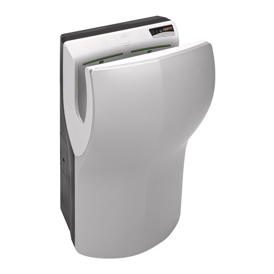
SECADORA DE MANOS / HAND DRYERS / SÉCHE-MAINS /
HÄNDETROCKNER / SECADOR DE MÃOS / ASCIUGAMANI /
جهاز
تجفيف
اليدين
M14A / M14ACS / M14AB
MANUAL DE INSTALACIÓN Y UTILIZACIÓN
INSTALLATION AND OPERATING MANUAL
MANUEL D'INSTALLATION ET D'UTILISATION
MONTAGE-UND BENUTZERHANDBUCH
MANUAL DE INSTALAÇÃO E UTILIZAÇÃO
MANUALE DI INSTALLAZIONE E D'USO
دليل االستخدام و التركيب
Inhaltsverzeichnis

Verwandte Anleitungen für Mediclinics M14A


Inhaltszusammenfassung für Mediclinics M14A
-
Seite 29: Sicherheitshinweise
DEUTSCH ç SICHERHEITSHINWEISE SICHERHEITSHINWEISE Bitte lesen und beachten Sie sorgfältig folgende Sicherheitshinweise, bevor Sie irgendwelche Vorgänge durchführen: - Die Vorrichtung darf ausschließlich durch einen qualifizierten Techniker installiert, eingestellt oder gewartet werden. All diese Vorgänge sind stets in Übereinstimmung mit den gegenwärtigen gesetzlichen europäischen Installationsstandards und den örtlichen Installationsvorschriften... - Seite 30 Strahl aus. Das Einführen der Hände unterbricht den Strahl und löst den Mechanismus des Trockners aus. Optionale Luftstromregulierung Mögliche Oberflächenfinish: Weiß (M14A) Seidenmatt (M14ACS) Schwarz (M14AB) Abmessungen: 665 mm (H) x 320 mm (B) x 226 mm (T) ...
-
Seite 31: Montage- Und Wartungsanleitung (Fachpersonal)
Im Versorgungsnetz sind Trennvorrichtungen mit einem Kontaktabstand von mindestens 3 mm an allen Polen vorzusehen. Diese Trennvorrichtungen müssen im das Festnetz integriert sein. MONTAGE- UND WARTUNGSANLEITUNG (FACHPERSONAL) Einleitung Die ‘Dualflow Plus’ Handtrocknerserie bietet folgende technischen Leistungen: Automatischer Betrieb. Sobald die Hände hineingesteckt werden, empfangen zwei Paar Infrarotsensoren die Bewegung und der Trockner schaltet sich automatisch ein. - Seite 32 Befestigen Sie den Händetrockner mithilfe der mitgelieferten oberen Metallplatte (Halterung) an der Wand. Hängen Sie den Trockner in diese Metallplatte ein, sobald sie montiert ist. Die untere Schraube sorgt für eine sichere Befestigung des Gerätes an der Wand. Verfahren Sie zum Zusammensetzen des Händetrockners in folgenden Schritten: ...
-
Seite 33: Wartung
Die Installationshöhe muss der Abbildung 3 entsprechen. Abb. 3 ACHTUNG: BEI ABMONTIERTEM GEHÄUSE LIEGEN DIE SPANNUNGSFÜHRENDEN TEILE DES GERÄTES FREI. Wartung MONTAGE, EINSTELLUNGEN UND WARTUNG DIESES HÄNDETROCKNERS DÜRFEN NUR VON QUALIFIZIERTEM FACHPERSONAL DURCHGEFÜHRT WERDEN. Einstellung der Motordrehzahl Drehen Sie das Sensor-Potenziometerrad wie in Abbildung 4, um die Motordrehzahl zu regulieren. -
Seite 34: Hinweise Zu Den Led-Anzeigen
Heizelement Diese Modelle Heizwiderstand enthält, haben einen EIN / AUS-Schalter einschalten. Abb. 4.1 Hinweise zu den LED-Anzeigen Die oben sichtbaren LEDs (Abbildung 5) geben an: 1.- Standby-Modus (grün) oder Betrieb (orange) 2.- Die rote LED leuchtet auf, wenn ein Motorproblem vorliegt (aufgrund einer Abnutzung der Stromabnehmer oder einer möglichen Blockierung) 3.- Die blaue LED leuchtet auf,... -
Seite 35: Austausch Des Aromatisierers
Austausch des Aromatisierers In Abbildung 7 sehen Sie, wie der Antigeruchseinsatz zu installieren ist. Abb. 7 Wasserbehälter Das Wasser aus dem Trockner wird in einem herausnehmbaren Behälter gesammelt. Wenn die maximale Kapazität des Wasserbehälters erreicht ist, ertönt ein akustischer Alarm und die blaue LED Lampe geht an (siehe Abb. -
Seite 36: Anschlussdiagramm
ANSCHLUSSDIAGRAMM Abb. 11 Abb. 12 Number Komponente PCB-Kabel des Infrarotsenders PCB-Kabel des Infrarotempfängers PCB-Kabel der LED-Anzeigen Wasserstandssensor Widerstand Schalter Schalrterkaebl Motorkabel Sicherung Versorgungskabel Motor-Einstellpotentiometer -36-... -
Seite 37: Grundlegende Explosionszeichnung
- Der Elektroinstallateur muss sich vergewissern, dass die Elektronik über einen den gültigen gesetzlichen Bestimmungen entsprechenden Erdanschluss verfügt. GEFAHR. - Vergewissern Sie sich, dass die Elektrik mit einem Stromschlaggefahr hochempfindlichen Unterbrecher I ∆ n ≤ 0,03 A ausgestattet ist. - Seite 65 -65-...
- Seite 69 ELIMINACIÓN DE RESIDUOS DE APARATOS ELÉCTRICOS Y ELECTRÓNICOS POR PARTE DE USUARIOS DOMÉSTICOS EN LA UNIÓN EUROPEA. El producto que ha adquirido ha sido diseñado y fabricado con materiales y componentes de alta calidad que pueden ser reciclados y reutilizados.
- Seite 72 MEDICLINICS, S.A. Industria, 54 E-08025 BARCELONA SPAIN Tel.: +34 934 464 700 Fax: +34 933 481 039 info@mediclinics.com 28/08/17 COD.: 9631007SMD www.mediclinics.com...