
Verwandte Anleitungen für Omron VARISPEED L7 CIMR-L7Z


Inhaltszusammenfassung für Omron VARISPEED L7 CIMR-L7Z
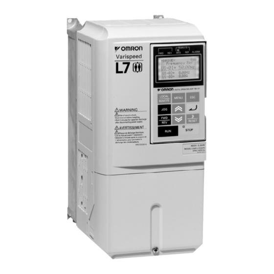
- Seite 1 Cat. No. I62E-EN-01 VARISPEED L7 Made to drive Lifts Model: CIMR-L7Z 200V Class 3-phase 3.7 to 55 kW 400V Class 3-phase 4.0 to 55 kW QuIck START GuIDE ...
-
Seite 2: Inhaltsverzeichnis
L7Z Quick Start Guide Table of Contents Warnings ................EN-1 Safety Precautions and Instructions ............. EN-2 EMC Compatibility ..................EN-3 Installation ..............EN-5 Mechanical Installation ................. EN-5 Electrical Connection ..................EN-6 Keypad Operation ............EN-11 Digital Operator Display (optional) ............. EN-11 Power Up and Basic Parameter Setup ......EN-12 Start Up Procedure .................. -
Seite 3: Warnings
Warnings CAUTION Cables must not be connected or disconnected, nor signal tests carried out, while the power is switched on. The Varispeed L7 DC bus capacitor remains charged even after the power has been switched off. To avoid an electric shock hazard, disconnect the frequency inverter from the mains before carrying out maintenance. -
Seite 4: Safety Precautions And Instructions
Safety Precautions and Instructions 1. General Please read these safety precautions and instructions for use thoroughly before installing and operating this inverter. Also read all of the warning signs on the inverter and ensure they are never damaged or removed. Live and hot inverter components may be accessible during operation. -
Seite 5: Emc Compatibility
This also applies to equipment with the CE mark. It is the responsibility of the manufacturer of the system or machine to ensure conformity with EMC limits. Contact your supplier or Omron-Yaskawa Motion Control representative when using leakage current circuit breaker in conjunction with frequency inverters. -
Seite 6: Laying Cables
2. Measures to Ensure Conformity of Omron-Yaskawa Motion Control Frequency Inverters to the EMC Directive Omron-Yaskawa Motion Control frequency inverters do not necessarily have to be installed in a switch cabi- net. It is not possible to give detailed instructions for all of the possible types of installation. This manual therefore has to be limited to general guidelines. -
Seite 7: Installation
Use a screwdriver or other tools to check for tightness. If you find any irregularities in the above items, contact the agency from which you purchased the Inverter or your Omron-Yaskawa Motion Control representative immediately. Checking the Installation Site Before installing the inverter check the following: Make sure that the ambient temperature is not exceeded •... -
Seite 8: Electrical Connection
Electrical Connection Installation of Inverters and EMC filters Ground Bonds Remove any paint! For an EMC rules compliant installation consider the following points: Use a line filter. • Use shielded motor cables. • Line Mount the inverter and filter on a grounded conductive plate. •... - Seite 9 Leakage current is caused by the Inverter. Therefore, if the distance between the ground electrode and the ground terminal is too long, potential on the ground terminal of the Inverter will become unstable. When more than one Inverter is used, do not to loop the ground wire. •...
- Seite 10 Table 2 Control Circuit Terminals with default settings Type Signal Name Function Signal Level Forward run/stop command Forward run when ON; stopped when OFF. Reverse run/stop command Reverse run when ON; stopped when OFF. Nominal speed Nominal speed when ON. Inspection Run Inspection RUN when ON.
- Seite 11 Table 3 Sinking/Sourcing Mode and Input Signals Internal Power Supply – Sinking Mode (NPN) External Power Supply – Sinking Mode (NPN) IP24V IP24V (+24V) (+24V) 24 VDC Internal Power Supply – Sourcing Mode (PNP) External Power Supply – Sourcing Mode (PNP) IP24V IP24V (+24V)
- Seite 12 Wiring the Inverter DC reactor to improve input Braking Resistor power factor (optional) unit (optional) Magnetic Link Contactor Motor (+1) (+2) L1(R) U/T1 3-phase power Line L2(S) V/T2 IM/PM 380 to 480V Filter 50/60Hz L3(T) W/T3 Forward run/stop Reverse run/stop Nominal Speed PG-X2 Inspection Run...
-
Seite 13: Keypad Operation
Keypad Operation Digital Operator Display (optional) The key names and functions of the Digital Operator are described below Drive Status Indicators FWD: Lights up when a forward run command is input. REV: Lights up when a reverse run command is input. SEQ: Lights up when any other run command source than the digital operator is selected... -
Seite 14: Power Up And Basic Parameter Setup
Power Up and Basic Parameter Setup Start Up Procedure START Mechanical installation Main and control circuit wiring Check the encoder power supply selection * (Closed Loop only) Switch on the power supply Select the control mode in parameter A1-02 Perform motor data / encoder offset auto tuning * V/f control page 16, Autotuning Procedure with Induction Motors * Open Loop Vector Control... -
Seite 15: Before Power Up
Before Power Up The following points should be checked carefully before the power is switched on. Check if the power supply meets the inverter specification. • Check if the power supply cables are tightly connected to the right terminals (L1, L2, L3). •... -
Seite 16: Autotuning
Autotuning The motor data autotuning function sets the V/f pattern parameters (E1- ), motor data parameters (E2- , E5- ) and the encoder data (F1-01) automatically. The steps which have to be performed during the autotuning depend on the tuning mode selection. Autotuning Mode Selection The autotuning mode has to be selected according to selected control mode and the mechanical system (motor no load rotation possible or not). -
Seite 17: Autotuning Alarms And Faults
General Precautions: 1. Use rotating autotuning whenever high precision is required or for a motor that is not connected to a load. 2. Use not rotating autotuning whenever the load cannot be disconnected from the motor (e.g. the ropes can’t be removed). -
Seite 18: Autotuning Procedure With Induction Motors
Autotuning Procedure with Induction Motors Fig 6 shows the autotuning procedure for an induction motor with or without encoder in V/f-, Open loop vec- tor and Closed loop vector control. START Set the Base Block Inputs BB and (A1-02 = 2/3) (ropes removed?) V/f Control ? Can the motor... -
Seite 19: Autotuning Procedure For Pm Motors
Autotuning Procedure for PM Motors Fig 7 shows the autotuning procedure for permanent magnet motors. Before tuning make sure that the control mode is set to PM Closed Loop Vector (A1-02 = 6). START * Remove the ropes so that the motor can rotate freely * Set the Base Block inputs BB and BB1 Switch ON the power supply if it is OFF Switch off the power supply... -
Seite 20: Pm Motor Encoder Offset Tuning
PM Motor Encoder Offset Tuning Fig 8 shows the autotuning procedure for an encoder offset tuning. The procedure should be performed if the encoder has been changed or has not been aligned correctly. Before tuning make sure that PM losed loop vec- tor control is selected (A1-02 = 6) and that the E1- and E5- parameters are set up correctly. -
Seite 21: Ride Profile And Sequence Setup
Ride Profile and Sequence Setup Up and Down Commands and Speed Reference Selection Up/Down Command Source Selection The input source for the Up and Down signal can be selected in parameter b1-02. The factory setting is Up/ Down command by the terminals S1/S2 (b1-02 = 1). Travel start in Up or Down direction To start in the elevator in Up or Down direction the following conditions have to be fulfilled: At least one speed reference must be selected if digital inputs are used for speed reference selection. - Seite 22 Speed Selection Table The following table shows the combinations of the digital input and the according speed. If b1-02 is set to “1”, frequency reference 1 is input as analog reference at terminal A1. Multi-step Multi-step Multi-step Selected Frequency Speed Speed Com- Speed Com- Speed Com-...
- Seite 23 When no speed selection input is set the leveling speed is taken as the speed reference. DC Injection/ DC Injection/ zero servo zero servo Speed Hardware BB Up/Down Selected speed The inverter stops when the direction signal (UP or DOWN signal) is removed. With this configuration the drive stops with a “FRL”...
-
Seite 24: Acceleration/Deceleration/Jerk Settings
Acceleration/Deceleration/Jerk Settings The acceleration time indicates the time to increase the speed from 0% to 100% of the maximum speed set in E1-04. The deceleration time indicates the time to decrease the speed from 100% to 0% of E1-04. The standard acceleration/deceleration times are set in the parameters C1-01/02, the jerk settings (S-curve) are set in the C2- parameters as shown in C2-03... - Seite 25 5. When the motor has stopped, apply a DOWN command. The inverter will accelerate the motor in the opposite direction to the nominal speed. Release the DOWN command a few seconds after the nominal speed has been reached. To abort the tuning set parameter n5-05 to “0”. 1.
-
Seite 26: Troubleshooting
Troubleshooting Fault and Alarm Detection Faults and Alarms are functions that indicate unusual inverter/application conditions. An alarm does not necessarily switch of the inverter but a message is displayed on the keypad and an alarm output is generated at the multi-function outputs (H2-01 to H2-03) if programmed. An alarm automatically disappears if the alarm condition is not present anymore. - Seite 27 Displayed as Display Meaning Corrective Actions Alarm Fault • Perform the complete tuning procedure FF_CAL Feed forward motor acceleration time active • Abort the tuning by setting n5-05 = 0. No speed was selected before the inverter start. Check the speed selection/start sequence. Ref Missing •...
-
Seite 28: Operator Programming Errors (Ope)
Displayed as Display Meaning Corrective Actions Alarm Fault The fuse in the main circuit is blown. • Check the motor and the motor cables for short cir- Warning: DC Bus Fuse cuits or insulation failures (phase-to-phase). Never run the Inverter after replacing the DC bus Open •... -
Seite 29: Auto-Tuning Faults
Auto-tuning Faults Auto-tuning faults are shown below. When the following faults are detected, the fault is displayed on the dig- ital operator and the motor coasts to stop. No fault or alarm outputs will be operated. Display Meaning Corrective Actions Acceleration error (detected during rotating autotuning •... -
Seite 30: Parameter Table
Parameter Table Note: Factory settings are in bold. Param. Name Description Num. Param. Name Description ASR propor- Set the proportional gain 3 and the inte- Num. C5-09 tional (P) gain 3 gral time 3 of the speed control loop Initialize Data (ASR) for the minimum frequency. -
Seite 31: Motor Protection
Param. Param. Name Description Name Description Num. Num. Feed forward Motor Data Settings Speed reference response will increase as n5-03 proportional E2-01 Rated current the setting of n5-03 is increased. gain E2-02 Rated slip Motor accelera- 0:Disabled E2-03 No-load current n5-05 1: Enabled tion time tuning... - Seite 32 Param. Param. Name Description Name Description Num. Num. U2-13 Operation status at fault U1-08 Output power in kW U2-14 Cumulative operation time at fault U1-09 Torque reference in % of the motor rated torque Fault History Data Shows input ON/OFF status. U3-01 Last fault to Fourth last fault 1: FWD command...
- Seite 33 EN-31...
- Seite 34 Kurzanleitung L7Z Inhaltsverzeichnis Warnhinweise ..............DE-1 Sicherheitshinweise und -anleitungen ............DE-2 Elektromagnetische Verträglichkeit .............. DE-3 Installation ..............DE-5 Mechanische Installation ................DE-5 Elektrischer Anschluss ................. DE-6 Tastaturbetrieb ............DE-11 Digitale Bedienkonsole (optional) ............... DE-11 Einschalten und Grundparameter-Einstellungen..DE-12 Inbetriebnahme ..................DE-12 Vor dem Einschalten .................. DE-13 Anzeige nach dem Einschalten ..............
-
Seite 35: Warnhinweise
Warnhinweise ACHTUNG Solange die Versorgungsspannung eingeschaltet ist, dürfen weder Kabel an- oder abgeklemmt werden, noch dürfen Signalprüfungen durchgeführt werden. Der Zwischenkreis des Varispeed L7 bleibt auch dann geladen, wenn die Spannungsversorgung unterbrochen wurde. Trennen Sie den Frequenzumrichter vor Ausführung von Wartungsarbeiten von der Spannungsversorgung, um einen elektrischen Schlag zu vermeiden. -
Seite 36: Sicherheitshinweise Und -Anleitungen
Sicherheitshinweise und -anleitungen 1. Allgemein Lesen Sie diese Sicherheitshinweise und -anleitungen vor Installation und Inbetriebnahme dieses Frequenzumrichters. Lesen Sie auch alle Warnhinweise, die auf dem Frequenzumrichter angebracht sind, und achten Sie darauf, dass diese nicht beschädigt oder entfernt werden. Während des Betriebs können unter Spannung stehende oder heiße Bauteile zugänglich sein. Durch Entfernen von Verkleidungsteilen, der digitalen Bedienkonsole oder Klemmenabdeckungen besteht im Falle einer fehlerhaften Installation oder Bedienung das Risiko von ernsthaften Verletzungen. -
Seite 37: Elektrischer Anschluss
Kabeln, beachten. Das gilt auch für Geräte, die das CE-Zeichen tragen. Es liegt in der Verantwortung des Herstellers von System oder Maschine, die Konformität mit den EMV-Richtlinien zu gewährleisten. Wenden Sie sich an Ihren Lieferanten oder die Omron-Yaskawa Motion Control-Vertretung, wenn Fehlerstrom-Schutzschalter in Verbindung mit Frequenzumrichtern Verwendung finden. -
Seite 38: Verlegen Von Kabeln
2. Maßnahmen zur Sicherstellung der Konformität von Omron-Yaskawa Motion Control-Frequenzumrichtern mit der EMV-Richtlinie Omron-Yaskawa Motion Control-Frequenzumrichter müssen nicht unbedingt in einen Schaltschrank eingebaut werden. Detaillierte Anleitungen für alle möglichen Installationsarten können nicht gegeben werden. Dieses Handbuch muss daher auf allgemeine Leitlinien begrenzt bleiben. -
Seite 39: Installation
Bauteile auf festen Sitz zu prüfen. Wenn Sie bei den oben genannten Punkten Unregelmäßigkeiten finden, teilen Sie dies sofort Ihrem Händler oder Ihrer Omron-Yaskawa Motion Control-Vertretung mit. Überprüfen des Installationsortes Überprüfen Sie vor dem Installieren des Frequenzumrichters folgende Punkte: Stellen Sie sicher, dass die Umgebungstemperatur nicht überschritten wird... -
Seite 40: Elektrischer Anschluss
Elektrischer Anschluss Installation von Frequenzumrichtern und EMV-Filtern Erdungs-Kontaktflächen Sämtliche Farbe entfernen! Bei einer Installation, die der EMV-Richtlinie entspricht, sind folgende Punkte zu beachten: Verwenden Sie einen Netzfilter. • Verwenden Sie abgeschirmte Motorkabel. • Netz- Montieren Sie Frequenzumrichter und Filter auf einer geerdeten, •... -
Seite 41: Sicherheitshinweise Für Die Verdrahtung Der Steuerstromkreise
Durch den Frequenzumrichter wird ein Leckstrom erzeugt. Wenn der Abstand zwischen der Erdungselektrode und der Erdungsklemme zu groß ist, wird das Potenzial an der Erdungsklemme des Frequenzumrichters instabil. Bei Einsatz von mehr als einem Frequenzumrichter darf der Erdungsleiter keine Schleife bilden. •... - Seite 42 Tabelle 2 Steuerklemmen mit Standardeinstellungen Signalbezeichnung Funktion Signalspezifikation Vorwärts-Start/Stopp-Befehl Vorwärts-Start bei EIN, Stopp bei AUS. Rückwärts-Start/Stopp-Befehl Rückwärts-Start bei EIN, Stopp bei AUS. Nenngeschwindigkeit Nenngeschwindigkeit bei EIN. Funktionen werden Inspektionslauf Inspektionslauf bei EIN. durch die Mittlere Geschwindigkeit 24 V DC, 8 mA Digitale Mittlere Geschwindigkeit Einstellungen...
- Seite 43 Tabelle 3 NPN/PNP-Betriebsart und Eingangssignale Interne Spannungsversorgung – NPN-Modus Externe Spannungsversorgung – NPN-Modus IP24 V IP24 V (+24 V) (+24 V) 24 V DC Interne Spannungsversorgung – PNP-Modus Externe Spannungsversorgung – PNP-Modus IP24 V IP24 V (+24 V) (+24 V) 24 V DC DE-9...
-
Seite 44: Verdrahten Des Frequenzumrichters
Verdrahten des Frequenzumrichters AC-Drossel zur Optimierung Bremswiderstands- des Eingangsleistungsfaktors Einheit (optional) (optional) Netz- Link schütz Motor (+1) (+2) L1(R) U/T1 3-Phasen- Netz- L2(S) V/T2 Eingangsspannung IM/PM filter 380 bis 480 V L3(T) W/T3 50/60 Hz Vorwärts Start/Stopp Rückwärts Start/Stopp Dreh- geber Nenngeschwindigkeit PG-X2... -
Seite 45: Tastaturbetrieb
Tastaturbetrieb Digitale Bedienkonsole (optional) Die Bezeichnungen der Tasten und die Funktionen der digitalen Bedienkonsole sind unten beschrieben. Antriebs-Statusanzeigen FWD: Leuchtet bei Eingang eines „Vorwärts“-Startbefehls. REV: Leuchtet bei Eingang eines „Rückwärts“-Startbefehls. SEQ: Leuchtet, wenn ein andere Quelle als die digitale Bedienkonsole für den Startbefehl gewählt ist. REF: Leuchtet, wenn für den Frequenzsollwert eine andere Quelle als die digitale Bedienkonsole gewählt ist. -
Seite 46: Einschalten Und Grundparameter-Einstellungen
Einschalten und Grundparameter-Einstellungen Inbetriebnahme START Mechanische Installation Verdrahtung der Haupt- und Steuerstromkreise Überprüfen Sie die Auswahl der Spannungsversorgung für den Drehgeber * (nur bei geschlossenem Regelkreis) Schalten Sie die Spannungsversorgung ein Wählen Sie die die Regelbetriebsart in Parameter A1-02 aus Führen Sie das Autotuning für die Motordaten/das Drehgeber-Offset durch * U/f-Regelung Seite 16, Autotuning-Verfahren bei Induktionsmotoren... -
Seite 47: Vor Dem Einschalten
Vor dem Einschalten Die folgenden Punkte sollten vor dem Einschalten der Spannungsversorgung sorgfältig überprüft werden. Kontrollieren Sie, ob die Versorgungsspannung den Spezifikationen des Frequenzumrichters entspricht. • Kontrollieren Sie, ob die Kabel der Spannungsversorgung fest an die richtigen Klemmen angeschlossen • sind (L1, L2, L3). -
Seite 48: Autotuning
Autotuning Die Motordaten-Autotuning-Funktion stellt die Parameter für die U/f-Kennlinie (E1- ), die Motordaten- Parameter (E2- , E5- ) und die Drehgeberdaten (F1-01) automatisch ein. Die Schritte, die während des Autotunings ausgeführt werden müssen, sind vom ausgewählten Autotuning-Modus abhängig. Auswahl des Autotuning-Modus Der Autotuning-Modus muss entsprechend der gewählten Regelbetriebsart und dem mechanischen System ausgewählt werden (Motorleerlauf möglich/nicht möglich). -
Seite 49: Autotuning-Alarme Und -Fehler
Allgemeine Sicherheitshinweise 1. Verwenden Sie das rotatorische Autotuning, wenn ein besonders präzises Autotuning erforderlich ist oder der Motor nicht mit einer Last verbunden ist. 2. Verwenden Sie immer das Autotuning im Stillstand, wenn die Last nicht vom Motor getrennt werden kann WICHTIG (z. -
Seite 50: Autotuning-Verfahren Bei Induktionsmotoren
Autotuning-Verfahren bei Induktionsmotoren Abb 6 zeigt das Autotuning-Verfahren bei einem Induktionsmotor mit oder ohne Drehgeber bei U/f- und Vektorregelung mit und ohne Rückführung. START Stellen Sie die Endstufensperreingänge BB und BB1 ein Nein (A1-02 = 2/3) (Seile entfernt?) U/f-Regelung? Kann sich der Motor (A1-02 = 0) frei drehen? Nein... -
Seite 51: Autotuning-Verfahren Bei Synchronmotoren
Autotuning-Verfahren bei Synchronmotoren Abb 7 zeigt das Autotuning-Verfahren bei Dauermagnet-Motoren. Vergewissern Sie sich vor der Abstimmung, dass die Regelbetriebsart auf PM-Vektorregelung mit Rückführung eingestellt ist (A1-02 = 6). START * Seile abnehmen, damit der Motor frei drehen kann * Endstufensperreingänge BB und BB1 einstellen Spannungsversorgung einschalten, falls diese ausgeschaltet ist Spannungsversorgung... -
Seite 52: Drehgeber-Offset-Einstellung Bei Synchronmotoren
Drehgeber-Offset-Einstellung bei Synchronmotoren Abb 8 zeigt das Autotuning-Verfahren bei einer Drehgeber-Offset-Einstellung. Das Verfahren sollte durchgeführt werden, wenn der Drehgeber ausgetauscht wurde oder nicht korrekt ausgerichtet ist. Vergewissern Sie sich vor der Abstimmung, dass die Regelbetriebsart PM-Vektorregelung mit Rückführung ausgewählt ist (A1-02 = 6) und dass die Parameter E1- und E5- korrekt eingestellt sind. -
Seite 53: Fahrprofil Und Sequenzeinstellung
Fahrprofil und Sequenzeinstellung Aufwärts-/Abwärtsbefehle und Drehzahlsollwert-Auswahl Auswahl der Quelle für den Aufwärts-/Abwärtsbefehl Die Eingangsquelle für das Aufwärts- und Abwärtssignal kann in Parameter b1-02 ausgewählt werden. Werksseitig ist der Aufwärts- und Abwärtsbefehl über die Klemmen S1/S2 (b1-02 = 1) eingestellt. Fahrbefehl in Aufwärts- oder Abwärtsrichtung Zum Starten des Aufzugs in Aufwärts- oder Abwärtsrichtung müssen folgende Bedingungen erfüllt sein: Wenn zur Auswahl des Drehzahlsollwerts digitale Eingänge verwendet werden, muss mindestens ein •... -
Seite 54: Drehzahl-Auswahltabelle
Drehzahl-Auswahltabelle In der nachstehenden Tabelle sind die Kombinationen aus Digitaleingangssignalen und entsprechender Drehzahl zusammengestellt. Ist b1-02 auf 1 gesetzt, wird Frequenzensollwert 1 als analoger Sollwert über Klemme A1 eingegeben. Gewählte Frequenz Geschwin- Festfrequenz- Festfrequenz- Festfrequenz- sollwert-Befehl 1 sollwert-Befehl 2 sollwert-Befehl 2 digkeit d1-18 = 0 d1-18 = 3... -
Seite 55: Separate Eingänge Für Die Drehzahlauswahl, Einfahrgeschwindigkeit Hat Priorität (D1-18 = 2)
Wenn kein Drehzahlauswahleingang aktiviert ist, wird die Einfahrgeschwindigkeit als Drehzahlsollwert genommen. DC-Bremsung/ DC-Bremsung/ Nullservo> Nullservo Geschwindigkeit Hardware-Endstufensperre Auf-/abwärts Ausgewählte Geschwindigkeit Der Frequenzumrichter stoppt bei Aufhebung des Aufwärts-/Abwärts-Richtungssignals. Bei dieser Konfiguration stoppt der Antrieb mit der Anzeige „FRL“ (Frequenzensollwertverlust- Fehler), wenn beim Start kein Drehzahlsollwerteingang ausgewählt ist. Um die FRL-Erkennung zu deaktivieren, setzen Sie Parameter S3-09 auf 0. -
Seite 56: Einstellungen Für Beschleunigung/Verzögerung/Ruckkontrolle
Einstellungen für Beschleunigung/Verzögerung/Ruckkontrolle Die Beschleunigungszeit entspricht der benötigten Zeit zur Erhöhung der Drehzahl von 0 % auf 100 % der in E1-04 eingestellten Maximaldrehzahl. Die Verzögerungszeit entspricht der benötigten Zeit zur Verringerung der Drehzahl von 100 % auf 0 % des in E1-04 definierten Wertes. Die standardmäßigen Beschleunigung-/Verzögerungszeiten werden in den Parametern C1-01/02 eingestellt, die Einstellungen für die Ruckkontrolle (S-Kurve) in den C2- Parametern, wie in... -
Seite 57: Vorsteuerungskompensation/Einstellung Der Proportionalverstärkung
5. Wenn der Motor gestoppt hat, geben Sie einen Abwärts-Befehl ein. Der Frequenzumrichter beschleunigt den Motor in Gegenrichtung bis zur Nenndrehzahl. Heben Sie den Abwärts-Befehl ein paar Sekunden lang auf, wenn die Nenndrehzahl erreicht ist. Um das Autotuning abzubrechen, setzen Sie Parameter n5-05 auf 0. 1. -
Seite 58: Fehlersuche Und Fehlerbehebung
Fehlersuche und Fehlerbehebung Fehler- und Alarmerkennung Fehler und Alarme sind Schutzfunktionen, die auf ungewöhnliche Bedingungen des Frequenzumrichters/ der Anwendung hinweisen. Bei einem Alarm wird der Frequenzumrichter nicht unbedingt ausgeschaltet, sondern eine Meldung angezeigt und eine Alarmausgabe an den Multifunktionsausgängen (H2-01 to H2-03) generiert, wenn dies programmiert ist. - Seite 59 Angezeigt als Anzeige Bedeutung Abhilfemaßnahmen Alarm Fehler • Führen Sie den gesamten Autotuningvorgang durch FF_CAL Vorsteuerung Motorbeschleunigungszeit aktiv • Um das Autotuning abzubrechen, setzen Sie Parameter n5-05 = 0. Vor dem Start des Frequenzumrichters wurde keine Überprüfen Sie die Drehzahlauswahl/Startsequenz. Ref Missing Drehzahl ausgewählt.
-
Seite 60: Fehler Bei Der Programmierung Durch Den Anwender (Ope)
Angezeigt als Anzeige Bedeutung Abhilfemaßnahmen Alarm Fehler Die Sicherung im Zwischenkreis ist durchgebrannt. Vorsicht: • Prüfen Sie den Motor und die Motorkabel auf Der Frequenzumrichter darf nach dem Ersatz der Kurzschlüsse oder Beschädigungen der Isolierung DC Bus Fuse Zwischenkreis-Sicherung nicht ohne Prüfung auf (zwischen den Phasen). -
Seite 61: Autotuning-Fehler
Autotuning-Fehler In der nachfolgenden Tabelle sind Autotuning-Fehler aufgeführt. Wenn einer der folgenden Fehler erkannt wird, wird der entsprechende Fehler auf der digitalen Bedienkonsole angezeigt, und der Motor läuft bis zum Halt aus. Es wird kein Fehler- oder Alarmausgang geschaltet. Anzeige Bedeutung Abhilfemaßnahmen •... -
Seite 62: Parametertabelle
Parametertabelle Hinweis:Werkseinstellungen sind in Fettdruck dargestellt. Param. Bezeichnung Beschreibung Param. Bezeichnung Beschreibung C5-09 ASR-Proportional- Einstellung der Proportionsverstärkung verstärkung (P) 3 3 und der Integralzeit 3 des Daten initialisieren Drehzahlregelkreises (ASR) für die 0:Englisch Mindestfrequenz. ASR- Sprachauswahl für 1: Japanisch C5-10 Die Einstellung ist nur bei Verzögerung Integrationszeit (I) 3 die Anzeige der... -
Seite 63: Einstellungen Für Motordaten
Param. Param. Bezeichnung Beschreibung Bezeichnung Beschreibung Bremssequenz Einstellungen für Motordaten Nulldrehzahl- E2-01 Nennstrom Einstellung des Drehzahlgrenzwerts für S1-01 grenzwert bei E2-02 Nennschlupf den Bremsbetätigungsbefehl bei Stopp. Stopp E2-03 Leerlaufstrom DC-Bremsstrom Motordaten für Asynchronmotore S1-02 E2-04 Anzahl der Pole beim Start Einstellung als Prozentsatz des Wicklungs- Frequenzumrichter-Nennstroms. -
Seite 64: Funktionsauswahl Der Digitaleingänge
Param. Param. Bezeichnung Beschreibung Bezeichnung Beschreibung Fehler-Speicherdaten Zeigt den EIN/AUS-Status der Eingänge an. U3-01 Letzter bis viertletzter Fehler 1: Vorwärts-Befehl U3-04 (S1) ist EIN U3-05 1: Rückwärts-Befehl Kumulative Betriebszeit bei Fehler 1 bis 4 (S2) ist EIN U3-08 1: Multif.-Eingang 1 Eingangs- (S3) ist EIN U3 09... - Seite 65 DE-31...
- Seite 66 Guía de referencia rápida de L7Z Tabla de contenido Advertencias..............ES-1 Precauciones de seguridad e instrucciones ..........ES-2 Compatibilidad EMC ..................ES-3 Instalación ..............ES-5 Instalación mecánica ..................ES-5 Conexión eléctrica ..................ES-6 Operación de teclado..........ES-11 Display del operador digital (opcional) ............ES-11 Encendido y configuración de parámetros básicos ..........ES-12 Procedimiento de arranque ................
-
Seite 67: Advertencias
Advertencias PRECAUCIÓN Mientras esté conectada la alimentación no deben ser conectados o desconectados cables ni se deben llevar a cabo pruebas de señal. El condensador de bus de c.c. del Varispeed L7 permanece cargado incluso una vez que la alimentación se ha desconectado. Para evitar el riesgo de descarga eléctrica desconecte el variador de frecuencia del circuito de alimentación antes de llevar a cabo trabajos de mantenimiento. -
Seite 68: Precauciones De Seguridad E Instrucciones
Precauciones de seguridad e instrucciones 1. General Lea detenidamente estas precauciones de seguridad e instrucciones de funcionamiento antes de instalar y operar este variador. Asimismo, lea todas las señales de advertencia que se encuentran en el variador y asegúrese de que nunca estén dañadas o falten. Es posible que se pueda acceder a componentes activos y calientes durante la operación. -
Seite 69: Compatibilidad Emc
Este manual se ha compilado para ayudar a los fabricantes de sistemas que utilizan variadores de frecuencia Omron-Yaskawa Motion Control a diseñar e instalar equipos eléctricos de conmutación. También describe las medidas necesarias para adecuarse a la Directiva EMC. Por lo tanto, deben seguirse las instrucciones de instalación y cableado de este manual. -
Seite 70: Tendido De Cables
2. Medidas para asegurar la conformidad de los variadores de frecuencia Omron-Yaskawa Motion Control a la Directiva EMC Los variadores de frecuencia Omron-Yaskawa Motion Control no se deben instalar necesariamente en un armario de maniobra. No es posible facilitar instrucciones detalladas para todos los tipos posibles de instalación. Por lo tanto, este manual se ha tenido que limitar a directrices generales. -
Seite 71: Instalación
Compruebe la firmeza de las uniones mediante un destornillador u otras herramientas. Si encuentra alguna irregularidad en los elementos anteriormente descritos, póngase en contacto con el distribuidor en el que ha adquirido el variador o con su representante Omron-Yaskawa Motion Control inmediatamente. Comprobación del lugar de instalación Antes de instalar el variador, compruebe los siguientes elementos: Asegúrese de que no se excede la temperatura ambiente... -
Seite 72: Conexión Eléctrica
Conexión eléctrica Instalación de variadores y filtros EMC Conexiones a tierra Quitar la pintura Para una instalación compatible con las normas EMC, tenga en cuenta los siguientes puntos: Utilice un filtro de línea. • Utilice cables blindados para el motor. •... - Seite 73 Utilice siempre un cable de tierra que cumpla las normativas técnicas sobre equipamiento eléctrico • y minimice su longitud. El variador provoca corriente de fuga. Por lo tanto, si la distancia entre el electrodo de tierra y el terminal de tierra es demasiado larga, el potencial en el terminal de tierra del variador se volverá inestable. Cuando utilice varios variadores, no forme lazos en el cable de tierra.
- Seite 74 Tabla 2 Terminales del circuito de control con configuraciones predeterminadas Tipo Nº Nombre de la señal Función Nivel de señal Comando de marcha directa/ Marcha directa cuando está en ON; parada cuando parada está en OFF. Comando de marcha inversa/ Marcha inversa cuando está...
- Seite 75 Tabla 3 Modo NPN/PNP y señales de entrada Fuente de alimentación interna: modo NPN Fuente de alimentación externa: modo NPN IP24V IP24V (+24 V) (+24 V) 24 Vc.c. Fuente de alimentación interna: modo PNP Fuente de Alimentación externa: modo PNP IP24V IP24V (+24 V)
- Seite 76 Cableado del variador Reactancia de c.c. para Unidad de resistencia mejorar factor de de frenado (opcional) potencia (opcional) Contactor Enlace magnético Motor (+1) (+2) L1(R) U/T1 Fuente de Filtro L2(S) V/T2 IM/PM alimentación trifásica de línea 380 a 480 V L3(T) W/T3 50/60 Hz...
-
Seite 77: Operación De Teclado
Operación de teclado Display del operador digital (opcional) Los nombres y funciones de las teclas del operador digital se describen más adelante Indicaciones del estado de controlador FWD: Se ilumina cuando se introduce un comando de marcha directa. REV: Se ilumina cuando se introduce un comando de marcha inversa. SEQ: Se ilumina cuando se selecciona una fuente de comandos de marcha distinta del operador digital. -
Seite 78: Encendido Y Configuración De Parámetros Básicos
Encendido y configuración de parámetros básicos Procedimiento de arranque INICIO Instalación mecánica Cableado del circuito principal y de control Comprobar la selección de fuente de alimentación del encoder * (Sólo lazo cerrado) Conectar la fuente de alimentación Seleccionar el modo de control en el parámetro A1-02 Realizar autotuning de datos de motor/desplazamiento de encoder * Control V/f... -
Seite 79: Antes Del Encendido
Antes del encendido Se deben comprobar atentamente los siguientes puntos antes de conectar la alimentación. Compruebe que la fuente de alimentación cumple la especificación del variador. • Compruebe que los cables de la fuente de alimentación están conectados firmemente a los terminales •... -
Seite 80: Autotuning
Autotuning La función de autotuning de los datos de motor establece automáticamente los parámetros de la curva V/f (E1- ), los parámetros de los datos del motor (E2- , E5- ) y los datos del encoder (F1-01). Los pasos que se tengan que realizar durante el autotuning dependen de la selección de modo de ajuste. Selección de modo de autotuning El modo de autotuning se tiene que seleccionar según el modo de control y el sistema mecánico elegidos (hay posibilidad o no de rotación del motor sin carga). -
Seite 81: Alarmas Y Fallos De Autotuning
Ajuste de desplazamiento del encoder (T1-01 = 4) Este modo de ajuste está disponible solamente en el modo de control vectorial de lazo cerrado para motores de imán permanente. Establece automáticamente el desplazamiento entre el polo magnético y la posición de cero magnético. -
Seite 82: Procedimiento De Autotuning Con Motores De Inducción
Procedimiento de autotuning con motores de inducción En la Fig. 6 se muestra el procedimiento de autotuning para un motor de inducción con encoder, o sin él, en control V/f, vectorial de lazo abierto y vectorial de lazo cerrado. INICIO Configurar las entradas de baseblock, BB y BB1 Sí... -
Seite 83: Procedimiento De Autotuning Para Motores De Imán Permanente
Procedimiento de autotuning para motores de imán permanente Fig. 7 muestra el procedimiento de autotuning para motores de imán permanente. Antes del ajuste, asegúrese de que el modo de control está configurado en vectorial de lazo cerrado de imán permanente (A1-02 = 6). INICIO * Quitar los cables para que el motor pueda girar libremente * Configurar las entradas de baseblock, BB y BB1... -
Seite 84: Ajuste De Desplazamiento De Encoder De Motor De Imán Permanente
Ajuste de desplazamiento de encoder de motor de imán permanente Fig. 8 muestra el procedimiento de autotuning para un ajuste de desplazamiento de encoder. El procedimiento se debe realizar si se ha cambiado el encoder o no se ha alineado correctamente. Antes del ajuste, asegúrese de que el control vectorial de lazo cerrado de imán permanente está... -
Seite 85: Perfil De Operación Y Configuración De Secuencia
Perfil de operación y configuración de secuencia Comandos UP y DOWN y selección de referencia de velocidad Selección de fuente de comando UP/DOWN La fuente de entrada para la señal UP o DOWN puede ser seleccionada en el parámetro b1-02. La configuración de fábrica es el comando UP/DOWN mediante los terminales S1/S2 (b1-02 = 1). - Seite 86 Tabla de selección de velocidad La siguiente tabla muestra las combinaciones de la entrada digital y la velocidad correspondiente. Si b1-02 está configurado en “1”, la referencia de frecuencia 1 se introduce como referencia analógica en el terminal A1. Frecuencia seleccionada Comando de Comando de Comando de...
- Seite 87 Cuando no está configurada ninguna entrada de selección de velocidad, la velocidad de nivelación se toma como referencia de velocidad. Inyección de c.c./ Inyección de c.c./ servo cero servo cero Velocidad BB de hardware UP/DOWN Velocidad seleccionada El variador se detiene cuando se retira la señal de dirección (señal UP/DOWN). Con esta configuración, el controlador para con un “FRL”...
-
Seite 88: Configuración De Aceleración/Deceleración/Sacudidas
Configuración de aceleración/deceleración/sacudidas El tiempo de aceleración indica el tiempo para incrementar la velocidad desde el 0% al 100% de la velocidad máxima configurada en E1-04. El tiempo de deceleración indica el tiempo para disminuir la velocidad desde el 100% al 0% de E1-04. Los tiempos de aceleración/deceleración estándar se configuran en los parámetros C1-01/02, la configuración de sacudidas (curva S) se configura en los parámetros C2- tal como se muestra en la... - Seite 89 5. Cuando el motor se haya parado, aplique un comando DOWN. El variador acelerará el motor en la dirección opuesta hasta la velocidad nominal. Cese el comando DOWN unos segundos después de que se haya alcanzado la velocidad nominal. Para anular el ajuste, configure el parámetro n5-05 a “0”. 1.
-
Seite 90: Detección Y Corrección De Errores
Detección y corrección de errores Detección de fallos y alarmas Los fallos y las alarmas son funciones que indican un estado anómalo del variador/aplicación. Una alarma no desconecta necesariamente el variador, sino que se muestra un mensaje en el teclado y se genera una salida de alarma en las salidas multifunción (H2-01 a H2-03) si así... - Seite 91 Se muestra Display como Significado Acciones correctivas Alarma Fallo • Realice el procedimiento de ajuste completo Tiempo de aceleración del motor de realimentación FF_CAL • Anule el ajuste mediante la configuración directa activo de n5-05 = 0. No se ha seleccionado velocidad antes de que Compruebe la selección de velocidad/secuencia arrancara el variador.
-
Seite 92: Errores De Programación Del Operador (Ope)
Se muestra Display como Significado Acciones correctivas Alarma Fallo El fusible del circuito principal está fundido. • Compruebe la existencia de cortocircuito o fallos Advertencia: de aislamiento en el motor y en los cables del motor DC Bus Fuse Nunca haga funcionar el variador tras sustituir (fase a fase). -
Seite 93: Fallos De Autotuning
Fallos de autotuning En este apartado se muestran los fallos de autotuning. Cuando se detectan los siguientes fallos, el fallo se visualiza en el operador digital y el motor marcha libre hasta detenerse. No se operan salidas de fallo o alarma. Display Significado Acciones correctivas... -
Seite 94: Tabla De Parámetros
Tabla de parámetros Nota: La configuración de fábrica está en negrita. Núme- ro de Nombre Descripción Núme- pará- ro de metro Nombre Descripción pará- Frecuencia de Configura la frecuencia para la metro C5-07 alternancia de alternancia entre la ganancia proporcional Inicialización de datos 1, 2, 3 y el tiempo de integral 1, 2, 3. - Seite 95 Núme- Núme- ro de ro de Nombre Descripción Nombre Descripción pará- pará- metro metro Configuración de datos de motor Ganancia La respuesta de referencia de velocidad proporcional de Corriente n5-03 se incrementará al incrementar E2-01 realimentación nominal la configuración de n5-03. positiva E2-02 Deslizamiento Ajuste...
- Seite 96 Núme- Núme- ro de ro de Nombre Descripción Nombre Descripción pará- pará- metro metro Datos monitorizados U2-10 Referencia de par en el fallo U2-11 Estado de terminal de entrada en el fallo U1-01 Referencia de frecuencia en Hz/r.p.m. U2-12 Estado de terminal de salida en el fallo U1-02 Frecuencia de salida en Hz/r.p.m.
- Seite 97 ES-31...
- Seite 98 Guide de démarrage rapide L7Z Sommaire Avertissements..............FR-1 Consignes de sécurité et instructions ............FR-2 Compatibilité CEM ..................FR-3 Installation ..............FR-5 Installation mécanique .................. FR-5 Connexions électriques ................FR-6 Utilisation du pavé numérique........FR-11 Affichage de la console numérique (en option) .......... FR-11 Mise sous tension et configuration des principaux paramètres..............FR-12 Procédure de démarrage ................
-
Seite 99: Avertissements
Avertissements ATTENTION Il est strictement interdit de brancher ou de débrancher des câbles ou de procéder à des tests de signalisation lorsque l’appareil est sous tension. Le condensateur de bus continu Varispeed L7 DC reste chargé d’électricité même lorsque l’alimentation est coupée. -
Seite 100: Consignes De Sécurité Et Instructions
Consignes de sécurité et instructions 1. Généralités Lire attentivement les précautions de sécurité et les instructions d’utilisation avant d’installer et d’utiliser le variateur. Contrôler également les dispositifs de sécurité du variateur et vérifier régulièrement leur état de fonctionnement (dommage ou démontage). Il est possible d’accéder aux éléments sous tension et aux éléments chauds pendant l’utilisation de l’appareil. -
Seite 101: Compatibilité Cem
CEM. Il est, de ce fait, impératif de respecter les instructions du manuel d’installation et les instructions de câblage. Les produits OMRON sont contrôlés par des instituts agréés utilisant les normes suivantes : Normes de produits : EN 61800-3:1996 EN 61800-3 ;... - Seite 102 2. Mesures pour garantir la conformité des variateurs de fréquence OYMC avec les directives CEM Il n’est pas nécessaire d’installer les variateurs de fréquence OYMC dans une armoire électrique. Il n’est pas possible de donner toutes les instructions en détails de toutes les configurations possibles d’installation.
-
Seite 103: Installation
Utilisez un tournevis ou d'autres outils pour vérifier le serrage des composants. façon lâche ? En cas d’anomalies constatées parmi celles indiquées ci-dessus, contactez immédiatement votre revendeur ou votre représentant Omron-Yaskawa Motion Control. Vérification du site d’installation Avant d’installer le variateur, vérifiez les éléments suivants : Assurez-vous que la température ambiante n’est pas dépassée. -
Seite 104: Connexions Électriques
Connexions électriques Installation des variateurs et des filtres CEM Protections au sol Enlevez la peinture ! Pour une installation conforme aux règles CEM, prenez en compte les points suivants : Utilisez un filtre de câblage. • Utilisez des câbles moteur blindé. •... - Seite 105 Le courant de fuite est engendré par le variateur. Par conséquent, si la distance entre l'électrode de terre et la borne de terre est trop longue, le potentiel sur la borne de terre du variateur deviendra instable. Lorsque vous utilisez plusieurs variateurs, n’enroulez pas le câble de terre. •...
- Seite 106 Tableau 2 Bornes du circuit de contrôle avec réglage par défaut n° Nom du signal Fonction Niveau du signal dèle Commande marche / arrêt avant Marche quand ON ; arrêt quand OFF Commande marche / arrêt inverse Marche inverse quand ON ; arrêté quand OFF Vitesse nominale Vitesse normale quand ON.
- Seite 107 Tableau 3 Mode NPN / source et signaux d'entrée Alimentation interne – mode NPN (NPN) Alimentation externe – mode NPN (NPN) IP24 V IP24 V (+24 V) (+24 V) 24 Vc.c. Alimentation interne – mode source (PNP) Alimentation externe – mode source (PNP) IP24 V IP24 V (+24 V)
- Seite 108 Câblage du variateur Self de lissage sur bus c.c. pour Unité de résistance améliorer le facteur de puissance de freinage (en option) d'entrée (en option) Contacteur Liaison magnétique Moteur (+1) (+2) L1 (R) U / T1 Alimentation Filtre de L2 (S) V / T2 IM / PM triphasée...
-
Seite 109: Utilisation Du Pavé Numérique
Utilisation du pavé numérique Affichage de la console numérique (en option) Les noms des touches et les fonctions de l'opérateur numérique sont décrits ci-dessous. Etats de fonctionnement du moteur FWD : s’allume lorsque la commande RUN est activée. REV : s’allume lorsque la commande RUN de marche arrière est activée. -
Seite 110: Mise Sous Tension Et Configuration Des Principaux Paramètres
Mise sous tension et configuration des principaux paramètres Procédure de démarrage DÉBUT Installation mécanique Câblage du circuit de contrôle et du circuit principal Contrôlez la sélection de l'alimentation du codeur * (Boucle fermée uniquement) Enclenchez l'alimentation Sélectionnez le mode de contrôle dans le paramètre A1-02 Exécutez l'autoréglage du décalage du codeur / des données du moteur * Contrôle V / f... -
Seite 111: Avant La Mise Sous Tension
Avant la mise sous tension Contrôlez soigneusement les points suivants avant la mise sous tension. Vérifiez si l’alimentation électrique répond aux spécifications du variateur. • Vérifiez si les câbles d'alimentation sont bien connectés aux bornes adéquates (L1, L2, L3). • Vérifiez si les câbles du moteur sont bien connectés aux bornes adéquates côté... -
Seite 112: Autoréglage
Autoréglage La fonction d’autoréglage des données du moteur définit automatiquement les paramètres du modèle V / f (E1- ), les paramètres de donnés du moteur (E2- , E5- ) et les données du codeur (F1-01). Les étapes à exécuter pendant l’autoréglage dépendent de la sélection du mode de réglage. Sélection du mode d’autoréglage Le mode d’autoréglage doit être sélectionné... -
Seite 113: Pannes Et Alarmes D'autoréglage
Consignes générales de sécurité : 1. Utilisez l’autoréglage avec rotation lorsqu’une grande précision est requise ou que le moteur n’est pas connecté ŕ une charge. 2. Utilisez l’autoréglage sans rotation si la charge ne peut pas être déconnectée du moteur (par exemple si les IMPORTANT câbles ne peuvent pas être retirés). -
Seite 114: Procédure D'autoréglage Des Moteurs À Induction
Procédure d’autoréglage des moteurs à induction Fig 6 illustre la procédure d’autoréglage d’un moteur à induction avec ou sans contrôle V / f-, contrôle de vecteur en boucle ouverte et contrôle de vecteur en boucle fermée. DÉBUT Spécifiez les entrées d'étage de sortie bloqué... -
Seite 115: Procédure D'autoréglage Des Moteurs Pm
Procédure d’autoréglage des moteurs PM Fig 7 illustre la procédure d’autoréglage pour les moteurs à aimant permanent. Avant de procéder au réglage, vérifiez si le mode de contrôle est réglé sur Contrôle du vecteur en boucle fermée des moteurs PM (A1-02 = 6). DÉBUT * Enlevez les câbles de manière à... -
Seite 116: Réglage Du Décalage Du Codeur Des Moteurs Pm
Réglage du décalage du codeur des moteurs PM Fig 8 illustre la procédure d’autoréglage lors d’un réglage de décalage du codeur. La procédure doit être exécutée si le codeur a été modifié ou s’il a été mal aligné. Avant de procéder au réglage, vérifiez si le contrôleur du vecteur en boucle fermée des moteurs PM est sélectionné... -
Seite 117: Configuration De La Séquence Et Du Profil De Déplacement
Configuration de la séquence et du profil de déplacement Sélection des commandes Up et Down et de la référence de vitesse Sélection d’une source de commande Up / Down Il est possible de sélectionner la source d’entrée du signal Up et Down dans le paramètre b1-02. Le réglage usine est la commande Up / Down par les bornes S1 / S2 (b1-02 = 1). - Seite 118 Tableau de sélection de vitesse Le tableau ci-dessous indique les combinaisons d’entrées numériques et les vitesses correspondantes. Si b1-02 est réglé sur « 1 », la référence de fréquence 1 est entrée comme référence analogique à la borne A1. Commande de Commande de Commande de Fréquence sélectionnée...
- Seite 119 Lorsque aucune entrée de sélection de vitesse n’est spécifiée, la vitesse de cadrage est utilisée comme référence de vitesse. Injection c.c. / Injection c.c. / servo zéro servo zéro Vitesse Matériel BB Up / Down Vitesse sélectionnée Le variateur s’arrête lorsque le signal de direction (signal UP ou DOWN) est éliminé. Avec cette configuration, le moteur s’arrête avec un «...
-
Seite 120: Réglages D'accélération / De Décélération / De Poussée
Réglages d’accélération / de décélération / de poussée Le temps d’accélération correspond au délai d’augmentation de la vitesse de 0 à 100 % de la vitesse maximale indiquée sous E1-04. Le délai de décélération correspond au délai de ralentissement de la vitesse de 100 à 0 % de E1-04. - Seite 121 5. Une fois le moteur arrêté, appliquez une commande DOWN. Le variateur accélère le moteur dans le sens inverse jusqu'à atteindre la vitesse nominale. Relâchez la commande DOWN pendant quelques secondes une fois la vitesse nominale atteinte. Pour annuler le paramètre de spécification du réglage n5-05 en lui affectant la valeur « 0 ». 1.
-
Seite 122: Correction Des Erreurs
Correction des erreurs Détection des pannes et des alarmes Les fonctions de panne et d’alarme indiquent des conditions de fonctionnement du variateur ou de l'application inhabituelles. En cas d’alarme, le variateur n’est pas nécessairement désactivé, mais un message apparaît sur le pavé numérique et une sortie d’alarme est générée au niveau des sorties multifonctions (H2-01 to H2-03) si cette option est programmée. - Seite 123 Affichage Ecran Signification Corrections Alarme Panne • Effectuez la procédure de réglage complète. Temps d’accélération du moteur d’entraînement avant FF_CAL • Annulez le réglage en spécifiant actif n5-05 = 0. Aucune vitesse n'a été sélectionnée avant que le Vérifiez la séquence de démarrage / sélection de Ref Missing variateur démarre.
-
Seite 124: Erreurs De Programmation De L'opérateur (Ope, Operator Programming Error)
Affichage Ecran Signification Corrections Alarme Panne Le fusible du circuit principal est sauté. • Vérifiez que le moteur et le câblage du moteur Avertissement : ne présentent pas de court-circuit ou de défaut DC Bus Fuse ne faites jamais fonctionner le variateur après avoir d’isolation (phase à... -
Seite 125: Pannes D'autoréglage
Pannes d’autoréglage Les erreurs d’autoréglage sont indiquées ci-dessous. Lorsque les erreurs suivantes sont détectées, l’erreur s’affiche sur l’opérateur digital et le moteur s’arrête par inertie. Aune alarme ou sortie d’erreur ne se déclenche. Ecran Signification Corrections Erreur d'accélération • Augmentez C1-01 (temps d'accélération 1). (détectée uniquement lors de l’autoréglage par rotation) •... -
Seite 126: Tableau Des Paramètres
Tableau des paramètres Remarque : Les réglages usine apparaissent en gras. Numéro du para- Description Numéro mètre du para- Description mètre Gain Permet de régler le gain proportionnel 3 C5-09 proportionnel (P) et au temps intégral 3 de la boucle de Initialisation des données ASR 3 contrôle de vitesse (ASR) de la fréquence... - Seite 127 Numéro Numéro du para- Description du para- Description mètre mètre Paramètres des données du moteur Gain d’avance La réponse de référence de vitesse n5-03 proportionnel augmente autant que le réglage de n5-03. E2-01 Courant nominal E2-02 Rated slip Réglage du temps 0 :Désactivé...
- Seite 128 Numéro Numéro du para- Description du para- Description mètre mètre Données de l’historique des erreurs U1-08 Alimentation en kW U3-01 à De la dernière erreur à la quatrième dernière erreur U1-09 Référence de couple en % du couple nominal du moteur U3-04 Indique l'état ON / OFF de la borne d'entrée.
- Seite 129 FR-31...
- Seite 130 Manuale di avvio rapido L7Z Sommario Avvertenze ...............IT-1 Misure per la sicurezza e istruzioni d'uso ............IT-2 Compatibilità elettromagnetica ...............IT-3 Installazione..............IT-5 Installazione meccanica .................IT-5 Collegamento elettrico ..................IT-6 Funzionamento tastierino ..........IT-11 Display della console di programmazione (opzionale) ......... IT-11 Accensione e impostazione di base dei parametri ..IT-12 Procedura di avvio ..................IT-12 Prima dell'accensione ...................IT-13 Display dopo l'accensione ................IT-13...
-
Seite 131: Avvertenze
Avvertenze ATTENZIONE Non collegare o scollegare dei cavi e non eseguire test di segnale quando l'alimentazione di corrente è attivata. Il condensatore del bus in continua Varispeed L7 rimane carico anche dopo la disattivazione dell'ali- mentazione. Per evitare il pericolo di scosse elettriche scollegare l’inverter dall’alimentazione prin- cipale prima di eseguire la manutenzione. -
Seite 132: Misure Per La Sicurezza E Istruzioni D'uso
Misure per la sicurezza e istruzioni d'uso 1. Generali Leggere per intero le seguenti misure per la sicurezza e le istruzioni d’uso prima di installare e far funzionare questo inverter. Leggere anche tutti i cartelli d’avviso sull’inverter e assicurarsi che non siano danneggiati o siano stati asportati. - Seite 133 Questo si riferisce anche ad apparecchiature con il contrassegno CE. Il produttore del sistema o della macchina è responsabile per la conformità dei limiti EMC. Contattare il proprio fornitore o il rappresentante di Omron-Yaskawa Motion Control se si utilizzano differenziali o magnetotermici insieme agli inverter.
-
Seite 134: Compatibilità Elettromagnetica
Compatibilità elettromagnetica 1. Introduzione Il presente manuale è stato redatto per aiutare i produttori di sistemi ad utilizzare gli inverter Omron-Yaskawa Motion Control per progettare e installare meccanismi elettrici di comando. Descrive anche le misure necessa- rie per adempiere alle direttive di compatibilità elettromagnetica (EMC). Per questo motivo bisogna seguire le istruzioni contenute nel manuale per l’installazione ed il cablaggio. -
Seite 135: Installazione
Utilizzare un cacciavite o altri attrezzi per controllare il serraggio. Se si riscontrano delle irregolarità negli elementi riportati sopra, contattare immediatamente il rivenditore presso il quale è stato acquistato l'inverter o il proprio rappresentate Omron-Yaskawa Motion Control. Controllo del luogo di installazione Prima di installare l'inverter eseguire le seguenti verifiche: Verificare che la temperatura ambiente non sia troppo elevata. -
Seite 136: Collegamento Elettrico
Collegamento elettrico Installazione di inverter e filtri EMC Collegamenti di messa a terra Eliminare qualsiasi Per un'installazione conforme alle regole di compatibilità elettro- traccia di vernice. magnetica (EMC), tenere conto dei seguenti elementi: Utilizzare un filtro di linea. • Utilizzare cavi motore schermati. •... -
Seite 137: Collegamento A Terra
Collegamento a terra Durante il collegamento a terra, è necessario osservare le precauzioni riportate di seguito. Evitare che il cavo di terra venga condiviso con altri dispositivi come saldatrici o macchine utensili. • Utilizzare sempre un cavo di terra conforme agli standard tecnici delle apparecchiature elettriche e il più •... - Seite 138 Tabella 2 Terminali del circuito di controllo con impostazioni predefinite Tipo Nome segnale Funzione Livello del segnale Comando di marcia avanti/arresto Marcia avanti quando è ON e arresto quando è OFF. Comando marcia indietro/arresto Marcia indietro quando è ON e arresto quando è OFF. Velocità...
- Seite 139 Tabella 3 Modalità sinking/sourcing e segnali d'ingresso Alimentazione interna – modalità sinking (NPN) Alimentazione esterna – modalità sinking (NPN) IP24V IP24V (+24 V) (+24 V) 24 VDC Alimentazione interna – modalità sourcing (PNP) Alimentazione esterna – modalità sourcing (PNP) IP24V IP24V (+24 V) (+24 V)
- Seite 140 Cablaggio dell’inverter Reattanza c.c. per migliorare il fattore Resistenza di frenatura di potenza in ingresso (opzionale) (opzionale) Contattore Collegamento magnetico Motore (+1) (+2) L1 (R) U/T1 Potenza trifase Filtro di L2(S) V/T2 IM/PM 380 ... 480 V linea 50/60 Hz L3(T) W/T3 Marcia avanti/Arresto...
-
Seite 141: Funzionamento Tastierino
Funzionamento tastierino Display della console di programmazione (opzionale) Di seguito vengono elencati i nomi dei tasti della console di programmazione e le funzioni ad essi associate. Spie stato di funzionamento FWD: si accende quando viene inserito un comando di marcia avanti. REV: si accende quando viene inserito un comando di marcia indietro. -
Seite 142: Accensione E Impostazione Di Base Dei Parametri
Accensione e impostazione di base dei parametri Procedura di avvio INIZIO Installazione meccanica Cablaggio dei circuiti di comando e principale Controllare la selezione dell'alimentazione dell'encoder * (solo anello chiuso) Attivare l'alimentazione Selezionare la modalità di controllo nel parametro A1-02 Eseguire l'autotuning dell'offset dell'encoder/dei dati motore * Comando V/f pagina 16, Procedura di autotuning con motori a induzione * Controllo vettoriale ad anello aperto... -
Seite 143: Prima Dell'accensione
Prima dell'accensione Prima di attivare l'alimentazione, è necessario verificare accuratamente quanto segue. Verificare che la tensione di alimentazione sia conforme alle specifiche dell'inverter. • Verificare che i cavi di alimentazione siano collegati saldamente ai terminali corretti (L1, L2, L3). • Verificare che i cavi motore siano collegati saldamente ai terminali corretti sul lato inverter (U, V, W) •... -
Seite 144: Autotuning
Autotuning La funzione di autotuning dei dati motore imposta automaticamente i parametri della linea caratteristica V/f (E1- ), i parametri dei dati motore (E2- , E5- ) e i dati encoder (F1-01). La procedura che deve essere eseguita durante l'autotuning dipende dalla selezione della modalità di tuning. Selezione modalità... -
Seite 145: Allarmi Ed Errori Di Autotuning
Precauzioni generali: 1. Utilizzare l’autotuning rotante ogni volta che è necessaria una precisione elevata oppure per un motore che non è collegato a un carico. 2. Utilizzare l’autotuning non rotante ogni volta che il carico non può essere scollegato dal motore IMPORTANTE (ad esempio le corde non possono essere rimosse). -
Seite 146: Procedura Di Autotuning Con Motori A Induzione
Procedura di autotuning con motori a induzione Fig. 6 mostra la procedura di autotuning per un motore a induzione con o senza encoder per il controllo V/f, vettoriale ad anello aperto e vettoriale ad anello chiuso. INIZIO Impostare gli ingressi del blocco delle basi BB e BB1 Sì... -
Seite 147: Procedura Di Autotuning Per Motori Pm
Procedura di autotuning per motori PM Fig. 7 mostra la procedura di autotuning per motori a magneti permanenti. Prima del tuning, accertarsi che la modalità di controllo sia impostata sul controllo vettoriale ad anello chiuso PM (A1-02 = 6). INIZIO * Rimuovere le corde in modo che il motore possa ruotare liberamente * Impostare gli ingressi del blocco delle basi BB e BB1 Attivare l'alimentazione qualora fosse disattivata. -
Seite 148: Tuning Dell'offset Dell'encoder Per Motori Pm
Tuning dell'offset dell'encoder per motori PM Fig. 8 mostra la procedura di autotuning dell'offset dell'encoder. La procedura deve essere eseguita se l'encoder è stato sostituito o non è stato allineato correttamente. Prima del tuning, accertarsi che sia selezio- nato il controllo vettoriale ad anello chiuso PM (A1-02 = 6) e che i parametri E1- ed E5- siano impo- stati correttamente.. -
Seite 149: Impostazione Profilo E Sequenza Di Funzionamento
Impostazione profilo e sequenza di funzionamento Comandi up e down e selezione velocità di riferimento Selezione sorgente di commando up/down La sorgente di input per il segnale up e down può essere selezionata nel parametro b1-02. L'impostazione di fabbrica è comando up/down sui terminali S1/S2 (b1-02 = 1). Lo spostamento inizia in direzione up o down Per far partire l’elevatore in direzione up o down si deve adempiere alle seguenti condizioni: Occorre selezionare almeno una velocità... - Seite 150 Tabella di selezione velocità La seguente tabella indica le combinazioni tra ingresso digitale e la velocità corrispondente. Se b1-02 viene impostato su “1”, la frequenza di riferimento 1 viene immessa come riferimento analogico sul terminale A1. Frequenza selezionata Comando di Comando di Comando di Velocità...
- Seite 151 Quando non è impostato alcun ingresso di selezione velocità, la velocità di livellamento viene utilizzata come velocità di riferimento. Iniezione c.c./ Iniezione c.c./ servo zero servo zero Velocità Hardware BB Up/down Velocità selezionata L’inverter si arresta quando viene annullato il segnale di direzione (UP o DOWN). Con questa configurazione, l'azionamento si arresta con un errore “FRL”...
-
Seite 152: Impostazioni Accelerazione/Decelerazione/Movimento A Strappi
Impostazioni accelerazione/decelerazione/movimento a strappi Il tempo di accelerazione indica il tempo per aumentare la velocità dallo 0% al 100% della velocità massima impo- stata in E1-04. Il tempo di decelerazione indica il tempo per diminuire la velocità dal 100% allo 0% di E1-04. I tempi standard di accelerazione/decelerazione sono impostati nei parametri C1-01/02, mentre i valori del movimento a strappi (curva a S) sono impostati nei parametri C2- , come indicato nella... - Seite 153 5. Quando il motore si è arrestato, applicare un comando DOWN. L'inverter accelera il motore nella dire- zione opposta fino al raggiungimento della velocità nominale. Rilasciare il comando DOWN alcuni secondi dopo il raggiungimento della velocità nominale. Per interrompere il tuning, impostare il parametro n5-05 su “0”. 1.
-
Seite 154: Soluzione Dei Problemi
Soluzione dei problemi Rilevamento errori e allarmi Gli errori e gli allarmi sono funzioni che indicano le condizioni normali dell'inverter/dell'applicazione. Un allarme non spegne necessariamente l'inverter, ma dà luogo alla visualizzazione di un messaggio sul tastie- rino e alla generazione di un allarme in corrispondenza delle uscite multifunzione (H2-01 ... H2-03), se programmate. - Seite 155 Visualizzazione Display Significato Azioni correttive Allarme Errore • Eseguire la procedura di tuning completa FF_CAL Tempo di accelerazione motore feed-forward attivo • Annullare il tuning impostando n5-05 = 0. Non è stata selezionata alcuna velocità prima dell'avvio Controllare la selezione della velocità/sequenza di Ref Missing dell'inverter.
-
Seite 156: Errori Di Programmazione Console (Ope)
Visualizzazione Display Significato Azioni correttive Allarme Errore Il fusibile nel circuito principale è guasto. Avviso: • Verificare la presenza di eventuali cortocircuiti Non azionare mai l’inverter dopo aver sostituito il fusibile bus o guasti nell'isolamento del motore e dei cavi del DC Bus Fuse Open in continua senza verificare la presenza di eventuali compo- motore (fase a fase). -
Seite 157: Errori Di Autotuning
Errori di autotuning Di seguito vengono indicati gli errori di autotuning. Quando vengono rilevati i seguenti errori, l’errore viene visualizzato sulla console di programmazione ed il motore continua a funzionare ad inerzia sino all’arresto completo. Non viene emesso alcun segnale di errore o di allarme. Display Significato Azioni correttive... -
Seite 158: Tabella Dei Parametri
Tabella dei parametri Nota: Le impostazioni di fabbrica sono in grassetto. Num. Nome Descrizione param. Num. Nome Descrizione C5-06 Ritardo ASR Imposta il tempo di ritardo di uscita ASR. param. Dati di inizializzazione Frequenza di Imposta la frequenza di commutazione tra il C5-07 commutazione guadagno proporzionale 1, 2 e 3 e il tempo... - Seite 159 Num. Num. Nome Descrizione Nome Descrizione param. param. Guadagno Il tempo di risposta della velocità Impostazioni dei dati motore n5-03 proporzionale di riferimento aumenterà con l’aumentare Corrente nomi- E2-01 feed-forward dell'impostazione di n5-03. nale Tuning tempo Scorrimento 0: Disabilitato n5-05 di accelerazione E2-02 1: Abilitato...
- Seite 160 Num. Num. Nome Descrizione Nome Descrizione param. param. U2-05 Corrente di uscita su errore Dati di monitoraggio U2-06 Velocità motore su errore U1-01 Frequenza di riferimento in Hz/giri al min. U2-07 Tensione di uscita di riferimento su errore U1-02 Frequenza di uscita in Hz/giri al min. U2-08 Tensione bus in continua su errore U1-03 Corrente di uscita in A U2-09 Potenza di uscita su errore...
- Seite 161 IT-31...
- Seite 162 Guia Rápido do L7Z Índice Atenção ................PT-1 Precauções de segurança e instruções ............PT-2 Compatibilidade EMC ................... PT-3 Instalação............... PT-5 Instalação mecânica ..................PT-5 Ligação eléctrica ..................PT-6 Funcionamento do teclado numérico ....... PT-11 Ecrã da consola digital (opcional) ...............PT-11 Arranque e configuração de parâmetros básica..
-
Seite 163: Atenção
Atenção AVISO Enquanto a alimentação estiver ligada os cabos não podem ser ligados ou desligados e não podem ser executados testes de sinal. O condensador do bus DC do Varispeed L7 permanece carregado mesmo após ter sido desligada a alimentação. Para evitar um choque eléctrico, desligue o variador de frequência do circuito antes de proceder a operações de manutenção. -
Seite 164: Precauções De Segurança E Instruções
Precauções de segurança e instruções 1. Geral Leia minuciosamente as precauções de segurança e instruções de utilização antes de instalar e trabalhar com o variador. Leia também todos os sinais de aviso no variador e assegure-se de que não são danificados ou removidos. -
Seite 165: Compatibilidade Emc
Também aplicável a equipamento com a marca CE. É responsabilidade do fabricante do sistema ou da máquina garantir a conformidade com os limites da EMC. Contacte o seu fornecedor ou o representante de controlo de movimento da Omron-Yaskawa quando utilizar o disjuntor de corrente de fuga em conjunção com os variadores de frequência. - Seite 166 2. Medidas para garantir a conformidade dos variadores de frequência de controlo de movimento da Omron-Yaskawa à directiva EMC. Os variadores de frequência de controlo de movimento da Omron-Yaskawa não necessitam de ser obrigatoriamente instalados num compartimento de comutação. Não é possível fornecer instruções detalhadas para todos os tipos de instalação possíveis. Este manual limita-se a fornecer as directrizes gerais.
-
Seite 167: Instalação
Utilize uma chave de fendas ou outras ferramentas para assegurar-se do aperto. com folga? Se encontrar quaisquer irregularidades nos itens listados, contacte imediatamente a agência onde comprou o variador ou o seu representante de controlo de movimento Omron-Yaskawa. Verificar o local de instalação Antes de instalar o variador verifique o seguinte: Certifique-se de que a temperatura ambiente não é... -
Seite 168: Ligação Eléctrica
Ligação eléctrica Instalação de variadores e filtros EMC Terra de protecção Remover a tinta existente! Para uma instalação de acordo com as normas EMC considere os pontos seguintes: Utilize um filtro de linha. • Utilize cabos de motor blindados. • Linha Monte o variador e o filtro numa placa condutora ligada à... - Seite 169 A corrente de fuga é provocada pelo variador. Assim, se a distância entre o eléctrodo de terra e o terminal de terra for demasiado longa, o potencial no terminal de terra do variador será instável. Quando for utilizado mais de um variador, não faça uma malha com o fio de terra. •...
- Seite 170 Tabela 2 Terminais do circuito de controlo com definições predefinidas Tipo N.º Nome do sinal Função Nível do sinal Comando de funcionamento Quando ligado, funcionamento directo; paragem directo/paragem quando desligado. Comando de funcionamento Quando ligado, funcionamento inverso; paragem inverso/paragem quando desligado. Quando ligado, velocidade Velocidade nominal nominal.
- Seite 171 Tabela 3 Modo NPN/PNP e sinais de entrada Fonte de alimentação interna – Modo NPN Fonte de alimentação externa – Modo NPN IP24V IP24V (+24V) (+24V) 24VDC Fonte de alimentação interna – Modo PNP Fonte de alimentação externa – Modo PNP IP24V IP24V (+24V)
- Seite 172 Ligar o variador Reactância DC para melhorar o factor Unidade de Resistência de de potência de entrada Frenagem (opcional) (opcional) Contactor Ligação magnético Motor (+1) (+2) L1(R) U/T1 Alimentação trifásica Filtro L2(S) V/T2 IM/PM 380 a 480 V de linha 50/60 Hz L3(T) W/T3...
-
Seite 173: Funcionamento Do Teclado Numérico
Funcionamento do teclado numérico Ecrã da consola digital (opcional) Os nomes das teclas e funções da consola digital são descritos abaixo Indicadores de estado do motor FWD: Acende-se com a entrada do comando de arranque de sentido directo. REV: Acende-se com a entrada do comando de arranque de sentido inverso. SEQ: Acende-se quando é... -
Seite 174: Arranque E Configuração De Parâmetros Básica
Arranque e configuração de parâmetros básica Procedimento de arranque START Instalação mecânica Ligações do circuito de controlo e do circuito principal Verifique a selecção da fonte de alimentação do codificador * (Apenas em malha fechada) Ligar a fonte de alimentação Seleccione o modo de controlo no parâmetro A1-02 Executar o ajuste automático do deslocamento do codificador/dados do motor... -
Seite 175: Antes De Ligar A Alimentação
Antes de ligar a alimentação Deverá verificar minuciosamente os pontos seguintes antes de ligar a alimentação. Verifique se a fonte de alimentação está de acordo com as especificações do variador. • Verifique se os cabos da fonte de alimentação estão ligados aos terminais correctos (L1, L2, L3). •... -
Seite 176: Ajuste Automático
Ajuste automático A função de ajuste automático dos dados do motor configura automaticamente os parâmetros do padrão V/f (E1- ), os parâmetros dos dados do motor (E2- , E5- ) e os dados do codificador (F1-01). Os passos que têm de ser executados durante o ajuste automático dependem da selecção do modo de ajuste. Selecção do modo de ajuste automático O modo de ajuste automático tem de ser seleccionado de acordo com o modo de controlo seleccionado e com o sistema mecânico (possibilidade ou não de rotação do motor sem carga). -
Seite 177: Alarmes E Falhas Do Ajuste Automático
Esclarecimentos gerais: 1. Utilize o ajuste automático rotativo quando for essencial uma precisăo elevada ou se o motor năo estiver ligado a uma carga. 2. Utilize o ajuste automático não rotativo quando a carga não poder ser desligada do motor IMPORTANTE (por exemplo, as cordas não podem ser removidas). -
Seite 178: Procedimento De Ajuste Automático Com Motores De Indução
Procedimento de ajuste automático com motores de indução Fig 6 apresenta o procedimento de ajuste automático para um motor de indução com ou sem codificador no controlo V/f, controlo vectorial de malha aberta e controlo vectorial de malha fechada. START Configure as entradas do base block BB e BB1 Não... -
Seite 179: Procedimento De Ajuste Automático Para Motores Pm
Procedimento de ajuste automático para motores PM Fig 7 apresenta o procedimento de ajuste automático para motores magnéticos permanentes. Antes do ajuste certifique-se de que o modo de controlo está configurado para vectorial em malha fechada para PM (A1-02 = 6). START * Remova as cordas para o motor rodar livremente * Configurar as entradas do Base Block BB e BB1... - Seite 180 Ajuste de deslocamento do codificador do motor PM Fig 8 apresenta o procedimento de ajuste automático para o ajuste de deslocamento do codificador. O procedimento deverá ser executado se o codificador for alterado ou se não foi alinhado correctamente. Antes do ajuste certifique-se de que está...
-
Seite 181: Perfil De Percurso E Configuração Da Sequência
Perfil de percurso e configuração da sequência Comandos Up e Down e selecção da velocidade de referência Selecção da origem dos comandos Up/Down A origem da entrada dos sinais Up e Down pode ser seleccionada no parâmetro b1-02. A configuração de fábrica provém dos terminais S1/S2 (b1-02 = 1). - Seite 182 Tabela de selecção de velocidade A tabela seguinte apresenta as combinações da entrada digital e velocidade correspondente. Se b1-02 estiver definido para “1”, a frequência de referência 1 é introduzida como referência analógica no terminal A1. Comando de Comando de Comando de Frequência seleccionada Dinâmico...
- Seite 183 Quando não é definida nenhuma entrada de selecção de velocidade, a velocidade de nivelamento é utilizada como velocidade de referência. Injecção de DC/ Injecção de DC/ servo zero servo zero dinâmico de Hardware do BB Up/Down Velocidade seleccionada O variador pára quando o sinal de direcção (sinal Up ou Down) é removido. Com esta configuração a transmissão pára com uma “FRL”...
-
Seite 184: Definições Da Aceleração/Abrandamento/Choque
Definições da Aceleração/Abrandamento/Choque O tempo de aceleração indica o tempo para incrementar a velocidade de 0% a 100% da velocidade máxima definida em E1-04. O tempo de desaceleração indica o tempo para decrementar a velocidade de 100% a 0% de E1-04. Os tempos de aceleração/desaceleração standard são definidos nos parâmetros C1-01/02, as definições de choque (curva S) são definidos nos parâmetros C2- conforme mostrado na... - Seite 185 5. Quando o motor parar, aplique um comando DOWN. O variador irá acelerar o motor na direcção oposta à velocidade nominal. Liberte o comando DOWN alguns segundos após ser atingida a velocidade nominal. Para abortar o parâmetro de definição de ajuste n5-05 para “0”. 1.
-
Seite 186: Resolução De Problemas
Resolução de problemas Detecção de falha e alarme As falhas e alarmes são funções que indicam condições do variador/aplicação fora do normal. Um alarme não desliga necessariamente o variador, mas é apresentada uma mensagem no teclado numérico e é gerada uma saída de alarme nas saídas multifunções (H2-01 to H2-03), se programado. Um alarme desaparece automaticamente se a condição que o gerou já... - Seite 187 Apresentada como Ecrã Significado Acções correctivas Alarme Falha Activo o tempo de aceleração do motor em • Execute a totalidade do procedimento de ajuste FF_CAL realimentação positiva • Aborte o ajuste configurando n5-05 = 0. Não foi seleccionada qualquer velocidade antes Verifique a selecção da velocidade/sequência Ref em falta do variador arrancar.
-
Seite 188: Erros De Programação Do Operador (Ope)
Apresentada como Ecrã Significado Acções correctivas Alarme Falha O fusível do circuito principal está rebentado. Aviso: • Verifique o motor e os cabos do motor por curto- Aberto o fusível do Nunca coloque em funcionamento o variador após circuitos ou falhas no isolamento (fase a fase). bus DC substituir o fusível do bus DC sem verificar se •... -
Seite 189: Falhas Do Ajuste Automático
Falhas do ajuste automático As falhas do ajuste automático são mostradas abaixo. Quando são detectadas as falhas seguintes a falha é apresentada na consola digital e o motor pára. Não serão geradas saídas de falha ou de alarme. Ecrã Significado Acções correctivas •... -
Seite 190: Tabela De Parâmetros
Tabela de parâmetros Nota: As definições de fábrica estão a cheio. Núm. Nome Descrição param. Núm. Nome Descrição Ganho param. Defina o ganho proporcional 3 e o tempo Inicializar dados C5-09 proporcional (P) integral 3 do ciclo de controlo de do ASR 3 velocidade (ASR) da frequência mínima. - Seite 191 Núm. Núm. Nome Descrição Nome Descrição param. param. Definições do dados do motor Ganho A resposta da velocidade de referência irá proporcional da E2-01 Corrente nominal n5-03 aumentar conforme a definição de n5-03 realimentação é aumentada. Patinagem positiva E2-02 nominal Ajuste do tempo 0:Desactivada Corrente sem...
- Seite 192 Núm. Núm. Nome Descrição Nome Descrição param. param. Dados de histórico de falhas U1-08 Potência de saída em kW U3-01 Última falha a quarta última falha U1-09 Binário de referência em % do binário nominal do motor U3-04 Apresenta o estado ON/OFF da entrada U3-05 Tempo de operação cumulativo na falha 1 a 4 U3-08...
- Seite 193 PT-31...
- Seite 194 Инструкция по быстрому запуску L7Z Содержание Предупреждения ............RU-1 Правила безопасности и указания по эксплуатации .......RU-2 Электромагнитная совместимость (ЭМС) ..........RU-3 Монтаж ................. RU-5 Механический монтаж ................RU-5 Подключение электрических цепей ............RU-6 Управление с клавиатуры ........RU-11 Цифровая панель управления (заказывается дополнительно) .... RU-11 Включение...
-
Seite 195: Предупреждения
Предупреждения ПРЕДУПРЕЖДЕНИЕ Ни в коем случае не подключайте и не отключайте кабели и не производите проверку сигнальных цепей при включенном питании. Конденсатор шины постоянного тока инвертора Varispeed L7 остается заряженным даже после отключения питания. Во избежание поражения электрическим током, прежде чем приступать к техническому обслуживанию, отсоедините преобразователь частоты... -
Seite 196: Правила Безопасности И Указания По Эксплуатации
Правила безопасности и указания по эксплуатации 1. Общие сведения Прежде чем приступать к монтажу и работе с инвертором, внимательно ознакомьтесь с настоящими правилами безопасности и указаниями по эксплуатации. Также прочитайте все предупреждающие надписи на инверторе и позаботьтесь о том, чтобы они не были повреждены или удалены. Некоторые... -
Seite 197: Электрические Соединения
Настоящее руководство было разработано с целью оказания помощи в проектировании и монтаже электрических распределительных устройств производителям систем, использующим преобразователи частоты OMRON YASKAWA Motion Control. В нем также описаны меры по обеспечению соблюдения Директивы по ЭМС. Таким образом, необходимо соблюдать указания по... - Seite 198 2. Меры по обеспечению соответствия преобразователей частоты Omron-Yaskawa Motion Control Директиве по ЭМС Преобразователи частоты Omron-Yaskawa Motion Control не обязательно устанавливать в шкаф. Предоставить подробные указания для всех возможных способов монтажа затруднительно. Поэтому настоящее руководство содержит только общие указания. Любое электрооборудование является источником радиоизлучений и сетевых помех...
-
Seite 199: Монтаж
Проверьте затяжку с помощью отвертки или других инструментов. крепежа. Если какой-либо из указанных выше критериев не соответствует норме, немедленно свяжитесь с поставщиком инвертора или с региональным представителем Omron Yaskawa Motion Control. Выбор места для монтажа При выборе места для установки инвертора руководствуйтесь следующими правилами: Температура... -
Seite 200: Подключение Электрических Цепей
Подключение электрических цепей Монтаж инверторов и ЭМС-фильтров Заземляющие поверхности Удалите краску и любое другое покрытие! Для выполнения требований ЭМС соблюдайте следующие правила: Используйте сетевой фильтр. • Для подключения двигателя используйте • фильтр экранированные кабели. Инвертор и фильтр монтируйте на заземленную Инвертор... - Seite 201 Поэтому, если расстояние между точкой заземления и клеммой заземления инвертора слишком велико, потенциал на клемме заземления инвертора будет нестабильным. При использовании более одного инвертора провода заземления не должны образовывать • замкнутый контур. НЕТ Рис. 1 Выполнение заземления Меры предосторожности при подключении цепей управления При...
- Seite 202 Таблица 2 Клеммы схемы управления и их функции, выбранные по умолчанию Тип Номер Наименование сигнала Функция Уровень сигнала Команда «Ход вперед/стоп» ВКЛ: Ход вперед; ВЫКЛ: Стоп Команда «Ход назад/стоп» ВКЛ: Ход назад; ВЫКЛ: Стоп ВКЛ: Номинальная Номинальная скорость скорость. Функции Пробный...
- Seite 203 Отрицательная/положительная логика (выбор NPN/PNP) С помощью перемычки CN5 для входов можно выбирать отрицательную (общий 0 В, NPN) или положительную (общий +24 В, PNP) логику управления. Также имеется возможность использования внешнего источника питания, что позволяет более гибко выбирать способы подачи сигналов. Таблица...
-
Seite 204: Подключение Инвертора
Подключение инвертора Дроссель постоянного тока для улучшения коэффициента Блок тормозного мощности на входе (опция) резистора (опция) Магнитный Пере- контактор мычка Двигатель (+1) (+2) L1(R) U/T1 3-фазное Сетевой L2(S) V/T2 IM/PM напряжение фильтр питания L3(T) W/T3 380 ... 480 В, 50/60 Гц Ход... -
Seite 205: Управление С Клавиатуры
Управление с клавиатуры Цифровая панель управления (опция) Ниже приведены названия и функции клавиш цифровой панели управления Индикаторы состояния привода FWD: Светится, когда подана команда «Ход вперед». REV: Светится, когда подана команда «Обратный ход». SEQ: Светится, когда источником подачи команды "Ход" выбрана... -
Seite 206: Включение Питания И Настройка Основных Параметров
Включение питания и настройка основных параметров Процедура запуска СТАРТ Выполните механический монтаж Подключите силовые цепи и цепи управления Проверьте правильность выбора напряжения питания энкодера * (Только для замкнутого контура) Подайте напряжения питания Выберите режим регулирования (A1-02) Выполните автоматическую настройку параметров двигателя / смещения энкодера * V/f-регулирование... -
Seite 207: Действия Перед Включением Питания
Действия перед включением питания Перед включением питания тщательно проверьте следующее: Соответствие напряжения питания характеристикам инвертора. • Надежность подключения кабелей питания к соответствующим клеммам (L1, L2, L3). • Надежность подключения кабелей двигателя к соответствующим клеммам на стороне • инвертора (U, V, W) и на стороне двигателя. Правильность... -
Seite 208: Автонастройка
Автонастройка Функция автонастройки параметров двигателя автоматически задает параметры V/f- характеристик (E1- ), параметры характеристик двигателя (E2- , E5- ) и параметр энкодера (F1-01). Последовательность действий, которые необходимо выполнить в ходе автонастройки, зависит от выбранного режима настройки. Выбор режима автонастройки Режим автонастройки выбирается в соответствии с выбранным режимом регулирования и типом механической... -
Seite 209: Предупреждения И Ошибки В Режиме Автонастройки
Общие меры предосторожности. 1. Используйте автонастройку с вращением тогда, когда требуется высокая точность или когда двигатель не подсоединен к нагрузке. 2. Если нагрузку от двигателя отсоединить невозможно (например, когда нельзя снимать тросы), ВАЖНО используйте автонастройку без вращения. 3. При выполнении автонастройки без вращения механический тормоз не должен быть отпущен. 4. -
Seite 210: Процедура Автонастройки Для Асинхронных Двигателей
Процедура автонастройки для асинхронных двигателей На Рис. 6 показана процедура автонастройки для асинхронного двигателя с энкодером или без энкодера в режиме V/f-регулирования, а также в режиме векторного регулирования с открытым и с замкнутым контуром. СТАРТ Замкните входы BB и BB1 Нет... -
Seite 211: Процедура Автонастройки Для Двигателей С Постоянными Магнитами
Процедура автонастройки для двигателей с постоянными магнитами На Рис. 7 показана процедура автонастройки для двигателей с постоянными магнитами. Перед началом настройки обязательно выберите режим векторного регулирования с замкнутым контуром для двигателей с пост. магнитами (A1-02 = 6). СТАРТ * Снимите все тросы, чтобы двигатель мог вращаться... -
Seite 212: Автонастройка Смещения Энкодера Для Двигателя С Постоянными Магнитами
Автонастройка смещения энкодера для двигателя с постоянными магнитами На Рис. 8 показана процедура автонастройки для определения смещения энкодера. Эта процедура выполняется после замены энкодера или в случае его неточного совмещения. Перед началом автонастройки убедитесь в том, что выбран режим векторного регулирования с... -
Seite 213: Настройка Профиля И Последовательности Движения
Настройка профиля и последовательности движения Команды «Вверх»/«Вниз» и выбор способа задания скорости Выбор источника команды «Вверх»/«Вниз» Источник сигналов «Вверх» и «Вниз» можно задать параметром b1-02. Изначально (заводская настройка) в качестве источника выбраны клеммы S1/S2 (b1-02 = 1). Начало движения вверх или вниз Чтобы... - Seite 214 Таблица выбора значений скорости В следующей таблице приведены комбинации сигналов на дискретных входах и соответствующие им значения скорости. Если параметр b1-02 = 1, задание частоты 1 вводится аналоговым сигналом на клемме A1. Команда Команда Команда Выбранная частота ступенч. ступенч. ступенч. Скорость...
- Seite 215 Если не включен ни один из входов выбора скорости, в качестве задания скорости принимается скорость выравнивания. Подпитка постоянным током/ Подпитка пост. током/ серворегулирование при серворегулирование при нулевой скорости нулевой скорости Скорость Блокировка выхода Вверх/Вниз Выбранная скорость При снятии сигнала направления («Вверх» или «Вниз») инвертор останавливается. При...
-
Seite 216: Настройка Параметров Разгона/Торможения/Сглаживания Толчков
Настройка параметров разгона/торможения/сглаживания толчков Время разгона – это время, за которое скорость возрастает от 0 % до 100 % от максимальной скорости, заданной параметром E1-04. Время торможения – это время, за которое скорость снижается от 100 % до 0 % от значения E1-04. Стандартные... - Seite 217 5. После остановки двигателя подайте команду DOWN (ВНИЗ). Инвертор начнет разгонять двигатель в противоположном направлении до номинальной скорости. Через несколько секунд после достижения максимальной скорости снимите команду DOWN. Для прекращения автонастройки сбросьте параметр n5-05 в 0. 1. Последовательность подачи команд UP или DOWN не имеет значения. 2.
-
Seite 218: Поиск И Устранение Неисправностей
Поиск и устранение неисправностей Сигнализация ошибок и предупреждений Функции обнаружения ошибок и формирования предупреждений предназначены для сигнализации ненормальных режимов работы инвертора/оборудования. В случае предупреждения инвертор может продолжать работу, на панели управления отображается предупреждающее сообщение и, если это запрограммировано, формируется сигнал предупреждения на многофункциональных... - Seite 219 поступали дольше времени, заданного в F1-14. Перегорел предохранитель в цепи электропитания. Предупреждение: Ни в коем случае не запускайте инвертор DC Bus Fuse • Обратитесь в сервисный центр Omron после замены предохранителя шины Open постоянного тока, не проверив силовые цепи на наличие короткого замыкания.
-
Seite 220: Ошибки Программирования (Ope)
Статус Код ошибки Описание Меры по устранению Пре- Оши- дупр. бка Нет отклика от выходного контактора дольше Ошибка Проверьте выходной контактор. времени S1-16. управления 1 Выходной ток при запуске составлял менее Ошибка Проверьте выходной контактор. 25 % тока холостого хода. управления... -
Seite 221: Ошибки Автонастройки
Ошибки автонастройки Ошибки автонастройки перечислены в следующей таблице. В случае обнаружения ошибки автонастройки ошибка индицируется на дисплее цифровой панели и двигатель останавливается в режиме вращения по инерции. Предупреждения при этом не формируются, выходы сигнализации ошибки не включаются. Код ошибки Описание Меры... -
Seite 222: Таблица Параметров
Таблица параметров Примечание: Жирным шрифтом выделены заводские Номер пара- Название Описание значения. метра Номер Время Задает время задержки на выходе C5-06 задержки пара- Название Описание ASR. выхода ASR метра Значение Задает значение частоты, при которой Параметры инициализации частоты происходит переключение между C5-07 Выбор... - Seite 223 Номер Номер пара- Название Описание пара- Название Описание метра метра Коэффициент Параметры двигателя передачи Номинальный пропорциональ Увеличение значения n5-03 повышает E2-01 n5-03 ток ного звена при отклик на задание скорости. Номинальное управлении с E2-02 скольжение прямой связью Ток Автонастройка E2-03 ненагруженного...
- Seite 224 Номер Номер пара- Название Описание пара- Название Описание метра метра Данные детализации ошибки 0:Очередность фаз выходного Очередность напряжения: U-V-W U2-01 Текущая ошибка S3-08 фаз выходного 1: Очередность фаз выходного напряжения U2-02 Последняя ошибка напряжения: U-W-V U2-03 Задание частоты при возникновении ошибки Диаметр...
- Seite 225 RU-31...