Herunterladen Inhalt Inhalt Diese Seite drucken
SELFSAT SNIPE DOME Bedienungsanleitung

SELFSAT SNIPE DOME Bedienungsanleitung

Automatic satellite antenna
Vorschau ausblenden Andere Handbücher für SNIPE DOME:
Inhaltsverzeichnis

Werbung

Verfügbare Sprachen
  • DE

Verfügbare Sprachen

I DO IT CO., LTD
#637, Smart-Hub Industry-University Convergence Center, 237 Sangidaehak-ro, Siheung-si, Gyeonggi-do, Korea (429-793)
TEL +82 (0)31 8041 1500
FAX +82 (0)31 8041 1550
E-MAIL sales@selfsat.com
WEB www.selfsat.com
Automatic
Automatic
Automatic
User's manual • Bedienungsanleitung • Manual utilisateur
• Manuale utente • Gebruikershandleiding
www.selfsat.com
ver 2.0
Satellite Antenna
Satellite Antenna
Satellite Antenna

Werbung

Inhaltsverzeichnis
loading

Inhaltszusammenfassung für SELFSAT SNIPE DOME

  • Seite 1 User’s manual • Bedienungsanleitung • Manual utilisateur • Manuale utente • Gebruikershandleiding I DO IT CO., LTD #637, Smart-Hub Industry-University Convergence Center, 237 Sangidaehak-ro, Siheung-si, Gyeonggi-do, Korea (429-793) www.selfsat.com TEL +82 (0)31 8041 1500 FAX +82 (0)31 8041 1550 E-MAIL sales@selfsat.com WEB www.selfsat.com...
  • Seite 2: Inhaltsverzeichnis

    7-1. Required space for the SNIPE DOME ............
  • Seite 3: General Information

    The first few pages of these instructions contain information about using the general functions of your SNIPE DOME, followed by an explanation of all the adjustment options. The last pages of the instructions cover various technical aspects of the SNIPE DOME.
  • Seite 4: Proper Use And Operation

    1-2. Proper use and operation This product has been designed for fixed installation on vehicles with maximum speeds of 130 km/h. It is designed to automatically aim an antenna at geostationary television satellites. The power to the system is supplied by a standard vehicle electrical system with a rated voltage of 12 or 24 Volts DC.
  • Seite 5: Safety Notes

    1-3. Safety Notes In order to ensure that your SNIPE DOME works properly you must ensure that it is following by the Operating Instructions in this manual and used as intended purpose. When it is correctly installed, the antenna automatically assumes the rest position when the ignition is switched on and locks itself.
  • Seite 6: Components Bundle

    2. Contents 2-1. Components Bundle Main unit Controller Cable (12m-Black color) Controller Controller bracket Receiver cable (12m – Grey color) Cigar jack adaptor Cable holder Cable gland Manual Screws M4x20(11), M4x16(2) User manual...
  • Seite 7: Name Of Parts

    2-2. Name of parts Main unit Antenna Mounting plate to Receiver (Option) to Controller to Receiver Controller GPS state light Power switch Stand by state light Bracket Satellite light Stand by button to Main unit Satellite Up/Down button USB port : For Satellite Information Update OK button Power port :...
  • Seite 8: Operating Instruction

    3. Operating Instruction 3-1. Connection Diagram MAIN UNIT Receiver cable (Grey color) RECEIVER CONTROLLER Use the controller cable to connect between the controller and antenna. The controller cable looks similar to the antenna receiver cable but you can distinguish them by the color and labeling.
  • Seite 9: Functional Description

    3-2. Functional Description A. Power On Function Description Operation When the all cable connections are completed, switch on “Power” Switch with the “Power Switch” button on the top of the controller. If the position of antenna was in Basic position, “STAND BY “Stand by”...
  • Seite 10 Description Operation GPS LED confirms the current location from 24 GPS satellites in the world. When your SNIPE DOME identifies a GPS signal, GPS LED light will remain on, regardless if the antenna is pausing or moving. “GPS” light GPS can help to search for the satellite faster & catch the optimum satellite signal, and assist SNIPE DOME to acheive the best elevation.
  • Seite 11: Quick Reference

    3-3. Quick Reference Classification Description Switch on with the “Power switch” button on the top of the controller. Upon power on, all LED will flash twice. Wait until “Stand by State” light & one “Satellite LED” light, which you set previously or the first satellite in the controller, remain solid on.
  • Seite 12: Program Update

    4. Program update 4-1. Connection Diagram for updating ※ Searching program with targeting satellites is pre-programmed. If there is no problem to search the satellites, do not need below update process. “USB port is used for Satellite Information Update only” MAIN UNIT CONTROLLER Controller Cable...
  • Seite 13: Update Process

    4-2. Update Process Using SNIPE DOME Update Program, refresh the satellite date of your SNIPE DOME. Please connect the main unit – controller – PC Download the update program on our website (http://www.selfsat.com) as the following instruction. Click [S/W update] of the model you want to update and download the update program.
  • Seite 14 Proceeding Update Open the installed update program and you will see the screen. Turn on the controller and click [Scan Ports]. The Port name might be different depending on the PC models. NOTE If you see [Invalid port] message after clicking [scan ports], please check if you selected the correct port, and if you see [Invalid port] message even if you chose the correct one, please change the setting as below;...
  • Seite 15 Open the data file(*.idt) as the pictures. Click [Connect] button and check [update] button has been activated as the following picture. Check the satellite and TP to update, and click [UPDATE]. NOTE At lease 1 TP should be selected for updating. Satellite should be updated one by one.
  • Seite 16 Lastly, operate the SNIPE DOME and see if it searches the updated satellite properly. If SNIPE DOME still cannot search the satellite even after the update was completed, please try updating again, or contact service@selfsat.com.
  • Seite 17: Trouble Shooting

    Satellite signals can be blocked or degraded by buildings, trees. Make sure there are no obstructions in a southward direction. Check your program of Controller often, and get the latest updates for your SNIPE DOME. C. Mechanical problems If the antenna does not move into desired position.
  • Seite 18: Specifications

    6. Specifications 6-1. Dimension 30.0cm 68.5cm 80.0cm 6-2. Specification Dimensions 800 x 685 x 300 mm Weight (Main Unit) 9.6 kg Antenna Gain 33.7 dBi @ 12.7GHz Min EIRP 50 dBW Polarization Linear (horizontal / Vertical) Output 1 output / 2 output (Optional) LNB Input Frequency 10.7 ~ 12.75 GHz LNB Output Frequency...
  • Seite 19: Camping Car Installation

    7. Camping Car Installation 7-1 . Required space for the SNIPE DOME Take care, that there is enough space for the SNIPE DOME, just as for the operation range. Vehicle rear 71.0cm Driving direction 30.0cm...
  • Seite 20: Equipment For Installation

    (same for all 4 mounting plate edges) FRONT Clean the surface with cleaner. Locate SNIPE DOME in the center of car roof. Attach friction tape outside of the mounting Put aside the mounting plate to apply silicone plate, to be 4mm away from it.
  • Seite 21 Put back the mounting plate on the silicone Apply silicone on the holes. applied and make 2holes (2mm) with power drill. Fix mounting plate on the car roof using 2 Re-apply silicone to cover tightened screws. M4x20 screws. Apply silicone around the mounting plate. Tidy the area silicone applied.
  • Seite 22 Equipment to initiate Cable holder installation. Put the cable inside the Cable holder as above picture. Arrange cable holder in front of (30cm apart Make 15mm drill hole in the center of the tape marking. from) antenna center by facing open side of cable holder toward projected part of the mounting plate.
  • Seite 23 Apply silicone around the cable holder. Fix cable holder on the car roof with 3 of M4x20 screws. Apply silicone around and on the top of screws. Tidy silicon. Connect black cable to the controller(middle) Remove friction tape . and grey cable to the receiver(Left). Fix the Controller Bracket (M4x16(2)) Use controller cable(Black Color) and Cigar jack adaptor to connect to the Controller.
  • Seite 24 7-1. Platzbedarf für SNIPE DOME ............. . .
  • Seite 25: Allgemeine Informationen

    Satelliten ausrichten kann, solange es sich in der Ausleuchtzone befindet. Die SNIPE DOME benötigt nur geringen Platz, während es die nötigen Anpassungen zur Ausrichtung der schlanken und agilen Antenne durchführt. Im allgemeinen Betrieb stellen Sie bitte sicher, dass das System immer eine ungehinderte Sicht auf den Himmel hat. Wenn das direkte Satelliten-Signal durch Hindernisse wie Berge, Gebäude oder Bäume unterbrochen...
  • Seite 26: Bestimmungsgemäße Verwendung

    1-2. Bestimmungsgemäße Verwendung Das vorliegende Produkt wurde für eine feste Installation auf Fahrzeugen mit einer Höchstgeschwindigkeit von 130 km/h konzipiert. Es richtet seine Antenne vollautomatisch auf geostationäre TV-Satelliten aus. Das System kann mit einer Standard- Fahrzeugspannung von 12 oder 24 Volt DC (Gleichstrom) versorgt werden. Das vorliegende Produkt darf nur für den in dieser Anleitung beschriebenen Zweck verwendet werden.
  • Seite 27: Sicherheitshinweise

    1-3. Sicherheitshinweise Um einen einwandfreien Betrieb der SNIPE DOME zu gewährleisten, müssen Sie sich vergewissern, dass alle Komponenten gemäß der vorliegenden Anleitung angeschlossen sind und wie vorgesehen verwendet werden. Wenn das System ordnungsgemäß montiert ist, nimmt die Antenne automatisch ihre vorgesehene Ruheposition ein, sobald die Zündung eingeschaltet wird.
  • Seite 28: Verpackungsinhalt

    2. Verpackungsinhalt 2-1. Lieferumfang Haupteinheit Steuergerätkabel (12m - Schwarze Farbe) Steuergerät Steuergeräthalterung Empfängerkabel (12m - Graue Farbe) Zigarettenanzünderkabel Kabelhalter Kabelverschraubung Manual Schraube M4x20(11), M4x16(2) Bedienungsanleitung...
  • Seite 29: Teilebezeichnung

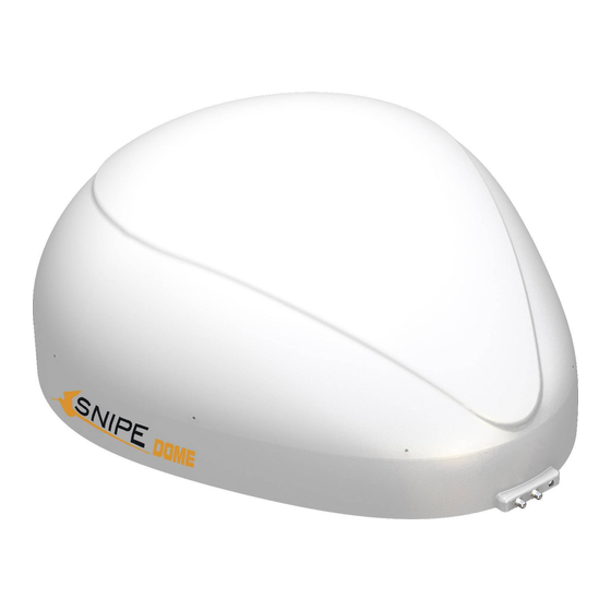
    2-2. Teilebezeichnung Haupteinheit Antenne Befestigungsplatte zum Satellitenempfänger(Option) zum Steuergerät zum Satellitenempfänger Steuergerät GPS-Statusanzeige Netzschalter Stand by-Statusanzeige Halterung Satellitenanzeige leuchtet auf Stand by-Taste Zur Haupteinheit Satelliten Auf/Ab-Tasten USB-Anschluss : Fur das Aktualisieren der Satelliten-Informationen OK-Taste Stromanschluss : DC 12~24V...
  • Seite 30: Anschlussdiagramm

    3. Bedienungsanweisungen 3-1. Anschlussdiagramm Haupteinheit Empfängerkabel (Graue Farbe) Steuergerät Empfänger Fernseher Verbinden Sie die Antenne mit dem controller über das schwarze controllerkabel. Beim Anschließen müssen Sie auf die Beschriftung und die Farbe der Kabel achten, weil die beiden Kabel die gleiche Form aufweisen.
  • Seite 31: Funktionsbeschreibung

    3-2. Funktionsbeschreibung A. Inbetriebnahme Funktion Beschreibung Bedienung Wenn alle Kabel fertig angeschlossen sind, schalten Sie den Netzschalter Netzschalter auf der Geräteoberseite ein. Wenn sich die Antenne in der Parkposition befindet, Stand by-Statusanzeige leuchtet die „Stand by-Statusanzeige“ auf, die eine leuchtet auf Betriebsbereitschaft anzeigt.
  • Seite 32 Beschreibung Bedienung Die GPS-LED bestätigt die Bestimmung der aktuellen Position über 24 GPS-Satelliten. Wenn SNIPE DOME die GPS-Signale identifiziert, leuchtet die GPS-LED unabhängig vom Betriebszustand der Antenne auf. GPS trägt zur Beschleunigung des Suchvorgangs und zum Auffangen des besten Satellitensignals bei, sodass SNIPE GPS-Anzeige DOME den benötigten Erhebungs- und Azimutwinkel...
  • Seite 33: Kurzanleitung

    3-3. Kurzanleitung Zuordnung Beschreibung Den Netzschalter auf der Geräteoberseite einschalten. Beim Einschalten des Geräts blinken alle LEDs zwei Mal. Warten bis Stand by-Statusanzeige und Satelliten-Statusanzeige aufleuchtet. Der Satellit kann entweder der Satellit, auf den sich die Antenne Bedienung zuletzt ausgerichtet hat, oder der erste Satellit auf dem Controller sein. (Suchen des Satelliten) Den gewünschten Satelliten auswählen und mit der OK-Taste bestätigen.
  • Seite 34: Programm-Update

    4. Program-Update 4-1. Anschlussdiagramm für das Update Suche Programm mit Targeting-Satelliten ist so vorprogrammiert. ※ Wenn es kein Problem, die Satelliten zu suchen, müssen nicht unten Update-Prozess. "Der USB-Anschluss wird nur fur das Aktualisieren der Satelliten-Informationen verwendet" Haupteinheit Steuergerät Steuergerätkabel (Schwarze Farbe) B type A type...
  • Seite 35: Update-Vorgang

    4-2. Update-Vorgang Mit SNIPE DOME Programm werden die Satellitendaten Ihres SNIPE DOME aktualisiert. Bitte verbinden Sie die Haupteinheit - Controller - PC. ii. Laden Sie das Update-Programm von unserer Website (http://www.selfsat.com) wie folgt herunter. Klicken Sie bei [S/W Update] auf das Modell, das Sie aktualisieren möchten und laden Sie das Update-Programm herunter.
  • Seite 36 Update durchführen Öffnen Sie das installierte Update-Programm und Sie sehen das Programmfenster. Schalten Sie den Controller ein und klicken Sie auf [Ports scannen]. Der Port-Name kann sich je nach PC-Modell unterscheiden. HINWEIS Wenn Sie die Meldung [ungültiger Port] nach dem Klicken auf [Scan Ports] sehen, überprüfen Sie bitte, ob Sie den richtigen Port ausgewählt haben und wenn Sie die Meldung [ungültiger Port] auch beim richtigen Port sehen, ändern Sie bitte die Einstellungen wie unten;...
  • Seite 37 Öffnen Sie die Datei (*.idt) wie auf den Bildern. Klicken Sie auf Schaltfläche [Connect] und prüfen Sie ob die [Update]-Taste aktiviert wurde, wie im folgenden Bild. Prüfen Sie Satellit und TP zum Aktualisieren und klicken Sie auf [Update]. HINWEIS Mindestens 1 TP sollte zum Aktualisieren ausgewählt sein.
  • Seite 38 Fehler] weiterhin angezeigt wird, nehmen Sie bitte andere Daten oder kontaktieren Sie service@selfsat.com. Zuletzt sollten das SNIPE DOME testen und überprüfen, ob es die aktualisierten Satelliten richtig findet. Wenn das SNIPE DOME, selbst nach der abgeschlossenen Aktualisierung, die Satelliten nicht finden kann, starten Sie das Update erneut oder wenden Sie sich an service@selfsat.com.
  • Seite 39: Fehlerbehebung

    5. Fehlerbehebung Es gibt eine Reihe von Ursachen, die die Signalqualität oder den Betrieb des SNIPE DOME beeinträchtigen können. Der folgende Abschnitt befasst sich mit den Ursachen und deren möglichen Lösungen. A. Keine Reaktion, wenn das Steuergerät eingeschaltet wird Sämtliche Anschlüsse erneut überprüfen.
  • Seite 40: Technische Daten

    6. Technische Daten 6-1. Abmessungen 30.0cm 68.5cm 80.0cm 6-2. Technische Daten Abmessungen 800 x 685 x 300 mm Gewicht (Haupteinheit ) 9.6 kg Antennengewinn 33.7 dBi @ 12.7GHz Min EIRP 50 dBW Polarisation Linear (horizontal / vertikal) LNB-Ausgang 1 Ausgang (optional 2 Ausgange) LNB-Eingangsfrequenz 10.7 ~ 12.75 GHz LNB-Ausgangsfrequenz...
  • Seite 41: Einbau Ins Wohnmobil

    7. Einbau ins Wohnmobil 7-1. Platzbedarf für das SNIPE DOME Achten Sie darauf , dass das SNIPE DOME genügend Platz zum Zusammenklappen sowie für den Betrieb hat. Fahrzeugheck 71.0cm Fahrtrichtung 30.0cm...
  • Seite 42: Ausrüstung Für Die Montage

    SNIPE DOME -Installation auf dem Dach (gleiche für alle 4 Montage-Plattenkanten) FRONT Reinigen Sie die Oberfläche mit dem Putzlappen. Lokalisieren SNIPE DOME in der Mitte auf dem Dach. Kleben Sie das Isolierband mit einem Abstand Legen Sie die Befestigungsplatte zur Seite und von 4mm um die Befestigungsplatte auf dem Dach.
  • Seite 43 Platzieren Sie die Befestigungsplatte auf dem Verteilen Sie das Silikon auf die Löchern. Silikon und bohren Sie 2 Löcher (2mm). Verschrauben Sie die Platte mit 2 Schrauben. Bedecken Sie die Schrauben mit Silikon. Verteilen Sie das Silikon um die Befestigungsplatte Glätten Sie das Silikon.
  • Seite 44 Ausrüstung zur Montage des Kabelhalters. Verlegen Sie die Kabel wie auf dem Bild zu sehen. Positionieren Sie den Kabelhalter mittig vor der Bohren Sie ein 15mm Loch in die Mitte der mit Antenne (30cm entfernt). Die offene Seite des Isolierband markierten Fläche. Kabelhalters soll Richtung Befestigungsplatte zeigen.
  • Seite 45 Verteilen Sie das Silikon um den Kabelhalter herum. Befestigen Sie den Kabelhalter auf dem Dach mit 3 M4x20 Schrauben. Verteilen Sie das Silikon auf den Schrauben. Glätten Sie das Silikon. Entfernen Sie das Isolierband. Verbinden Sie das schwarze Kabel mit dem Steuergerät (Mitte) und das graue Kabel mit dem Empfänger (links).
  • Seite 46 7-1. Espace requis pour SNIPE DOME ............. . .
  • Seite 47: Informations Générales

    Un fonctionnement correct et sûr du système ne peut être assuré qu’en suivant ces instruc- tions. Votre SNIPE DOME est un système d'antenne de réception TV satellite intelligente qui peut s'aligner vers un satellite prédéfini automatiquement tant que le système se trouve dans l'empreinte de ce satellite.
  • Seite 48: Utilisation Et Fonctionnement Corrects

    1-2. Utilisation et Fonctionnement corrects Ce produit a été conçu pour une installation fixe sur des véhicules avec des vitesses maximales de 130 km / h. Il est conçu pour diriger automatiquement une antenne sur des satellites de télévision géostationnaires. L'alimentation du système est fournie par un système électrique de véhicule standard avec une tension nominale de 12 ou 24 Volts en courant continu.
  • Seite 49: Consignes De Sécurité

    1-3. Consignes de Sécurité Afin de s’assurer que votre SNIPE DOME fonctionne correctement vous devez vous assurer qu'il suit le mode d'emploi de ce manuel et est utilisé aux fins prévues. Quand il est correctement installé, l'antenne se met automatiquement en position de repos lorsqu’on met le contact et se verrouille.
  • Seite 50: Ensemble De Composants

    2. Contenu 2-1. Ensemble de Composants Unité principale Câble du contrôleur (12m - Couleur Gris) Contrôleur Contrôleur bras de fixation Câble du recépteur (12m - Couleur Noire) Cigar lighter jack câble Support de câble Presse-étoupe Manual Vis M4 × 20 (11) , M4 × 16 (2) Manuel d'utilisation...
  • Seite 51: Noms Des Pièces

    2-2. Nom des pièces unité principale Antenne Plaque de montage vers le récepteur (Option) vers le contrôleur vers le récepteur Contrôleur Voyant d’état du GPS Interrupteur d’alimentation Voyant d’état Stand by Controleur bras de fixation Voyant du Satellite Bouton Stand by vers l’Unité...
  • Seite 52: Mode D'emploi

    3. Mode d’Emploi 3-1. Schéma de connexion Unité Principale Câble du récepteur (Couleur grise) RECEPTEUR CONTRÔLEUR Utilisez le câble de couleur noir du contrôleur pour relier ce dernier à l'antenne. Les deux câbles du contrôleur et du récepteur semblent identiques , merci de les identifier par leur couleurs respectives.
  • Seite 53: Description Des Fonctions

    3-2. Description des Fonctions A. Sous Tension Fonction Description Fonctionnement Lorsque toutes les connexions sont terminées, allumez Interrupteur avec le bouton "Interrupteur d'alimentation" sur le dessus d'alimentation du contrôleur. Si l'antenne était à la position repose, le voyant "Stand by" Voyant “Stand by”...
  • Seite 54 La LED GPS confirme la localisation exacte à partir de 24 satellites GPS dans le monde. Lorsque votre SNIPE DOME identifie le signal GPS, le voyant LED GPS se fixe, peu importe si votre antenne est à l'arrêt ou en mouvement.
  • Seite 55: Rapide Tour De Références

    3-3. Rapide tour de Références Classification Description Allumer avec le bouton “Interrupteur d’alimentation” sur le dessus du contrôleur. Après mise sous tension, toutes les LED clignoteront deux fois. Attendez jusqu'à ce que le voyant "Etat Stand by" et un voyant “LED du Satellite”...
  • Seite 56: Mise À Jour Du Programme

    4. Mise à jour du Programme 4-1. Schéma de Connexion pour la Mise à jour ※ programme cherchez à cibler les satellites est pré-programmé. Se il n'y a aucun problème pour rechercher les satellites, ne ont pas besoin de mise à...
  • Seite 57: Le Processus De Mise À Jour

    4-2. Le processus de mise à jour : A l’aide du programme de mise à jour SNIPE DOME, mettre à jour les données de son SNIPE DOME par satellite. Faire la connexion : l'unité principale - le contrôleur - PC Télécharger les mises à...
  • Seite 58 Suite de Mises à jour Ouvrez le programme installé de mises à jour et vous voyez l'écran. Connectez le contrôleur et appuyez sur [ports numérisation]. Le nom du port peut différer selon le modèle de PC. REMARQUE Si vous voyez un message [Le port non valide] après avoir appuyé sur les [ports numérisation], assurez-vous de sélectionner le port correct, et si vous voyez le message [port non valide] même si vous sélectionnez le port correct, modifier les paramètres comme indiqué...
  • Seite 59 Ouvrez le fichier de données (* .idt) comme les photos le montrent. Appuyez sur [Connect] et assurez-vous que la touche [mise à jour] était activé comme indiqué sur l'image ci-dessous. Vérifiez le satellite et TP, pour mettre à jour et cliquez sur [Mise à...
  • Seite 60 [Erreur Format de données], entrez d'autres données ou contactez service@selfsat.com Enfin, branchez SNIPE DOME et voyez s’il détecte dûment un satellite mis à jour. Si SNIPE ne peut toujours pas trouver le satellite, même après la mise à jour accomplie, essayez la mise à...
  • Seite 61: Dépannage

    5. Dépannage Il ya un certain nombre de problèmes communs qui peuvent affecter la qualité de réception du signal ou le fonctionnement de la SNIPE DOME. Les sections suivantes traitent de ces questions et les solutions possibles. A. Pas de réaction lors de la mise en tension du contrôleur.
  • Seite 62: Caractéristiques

    6. Caracteristiques 6-1. Dimensions 30.0cm 68.5cm 80.0cm 6-2. Caracteristiques Dimensions 800 x 685 x 300 mm Poids 9.6 kg Gaindel'antenne 33.7 dBi @ 12.7GHz MinEIRP 50 dBW Polarisation Linéaire (Horizontale/ Vericale) SortieLNB 1 sortie (2 sorties optionel) Fréquenced'entréeLNB 10.7 ~ 12.75 GHz FréquencedesortieLNB 950 ~ 2,150MHz rayon d'angle...
  • Seite 63: Installation Dans Le Camping Car

    7 . Installation dans le Camping Car 7-1 . Espace requis pour SNIPE DOME Prenez garde, qu'il ya suffisamment d'espace pour le SNIPE DOME, tout comme pour la plage de fonctionnement. l'arrière du véhicule 71.0cm Direction de conduite 30.0cm...
  • Seite 64: Equipement D'installation

    Foret de 2 mm, 15mm Silicone Perceuse Nettoyeur Installation de la SNIPE DOME sur le Toit du Véhicule (même pour tous les quatre bords de la plaque de montage) FRONT Nettoyer la surface avec un chiffon. Localiser l'emplacement de la SNIPE DOME sur le toit du véhicule.
  • Seite 65 Remettre le SNIPE DOME sur le silicone Appliquez de la silicone. appliqué et de faire 2 trous (2mm) avec perceuse. Fixer la plaque de montage sur le toit de la Re-appliquer le silicone pour couvrir vis voiture en utilisant 2 vis M4x20.
  • Seite 66 Equipement pour lancer l'installation du Mettez le câble à l'intérieur du support de câble support de câble. que l'image ci-dessus. Disposer support de câble en face de (30cm à Faire un trou de 15mm de forage dans le centre part) de centre de l'antenne en faisant face côté de la bande de marquage.
  • Seite 67 Appliquez de la silicone autour du passe tout, y Fixer le passe toit sur le toit du véhicule avec 3 compris autour des vis. vis M4x20 de. Appliquez de la silicone autour et sur le dessus La surface silicone rangée. de vis.
  • Seite 68 7-1. Benodigde ruimte voor de SNIPE DOME ..........
  • Seite 69: Algemene Informatie

    De eerste paar pagina’s van deze instructies bevatten informatie over de algemene functies van uw SNIPE DOME, gevolgd door een uitleg over alle instellingsopties. De laatste pagina’s van de instructies gaan over verschillende technische aspecten van de SNIPE DOME.
  • Seite 70: Correct Gebruik En Bediening

    1-2. Correct gebruik en bediening Dit product is ontworpen om te monteren op voertuigen met maximum snelheden tot 130 km/u. De antenne is ontworpen om zich automatisch op geostationaire TV-satellieten te richten. De stroomvoorziening van het systeem word verzorgd door het standaard elektrische systeem van het voertuig met een gelijkspanning van 12V of 24V.
  • Seite 71: Veiligheidsinstructies

    1-3. Veiligheidsinstructies Om er zeker van te zijn dat uw SNIPE DOME juist werkt, moet u ervoor zorgen dat de bedieningsinstructies in deze handleiding gevolgd worden en gebruikt wordt zoals bedoeld. Als het systeem correct geïnstalleerd is, zal de antenne automatisch de ruststand aannemen en zich in deze positie vergrendelen als de motor gestart wordt.
  • Seite 72: Onderdelenlijst

    2. Inhoud 2-1. Onderdelenlijst Hoofdunit Bedieningkabel (12m - zwart) Bediening Beugel voor Bediening Ontvangerkabel (12m – grijs) Stroomkabel met sigarettenplug Kabelhouder Kabelwartel Manual Bout M4 × 20 (11) ,M4 × 16 (2) Gebruikshandleiding...
  • Seite 73: Naam Van Onderdelen

    2-2. Naam van onderdelen Hoofdunit Antenne Montageplaat naar ontvanger (optioneel) naar bediening naar ontvanger Bediening GPS statusindicator Aan-/Uit knop Stand by statusindicator Beugel Sateliiet indicator Stand by knop Naar hoofdunit Satelliet Omhoog/Omlaag knop USB poort : Voor Satellite information update OK knop Stroomingang : DC 12~24V...
  • Seite 74: Bedieningsinstructies

    3. Bedieningsinstructies 3-1. Verbindingsdiagram Hoofdunit Ontvangerkabel (grijs) Ontvanger Bediening Gebruik de zwarte kabel om de besturing aan de schotel te koppelen. Gebruik een andere kleur kabel, of markeer ze, om onderscheid te houden voor de kabel naar de receiver.
  • Seite 75: Beschrijving Van De Functies

    3-2. Beschrijving van de functies A. Aanzetten Functie Omschrijving Bediening Als alle kabels correct zijn aangesloten, zet dan het apparaat “Aan-/uit” knop aan met de aan-/uit knop boven op de bediening. Als de antenne in de ruststand staat, zal de “Stand by “Stand by Status”...
  • Seite 76 Bediening De GPS indicator bevestigt de positie via 24 GPS satellieten over de hele wereld. Als uw SNIPE DOME een GPS signaal identificeert zal de GPS LED indicator continu oplichten, ongeacht of de antenne stil staat of beweegt. Met GPS kan een satelliet sneller gevonden worden, “GPS”...
  • Seite 77: Snelle Naslag

    3-3. Snelle naslag Soort Beschrijving Zet het apparaat aan met de “aan-/uitknop” boven op de bediening. Alle indicatoren knipperen tweemaal als het apparaat wordt aangezet. Wacht tot “Stand by status” en de “Satelliet” indicator van de door u reeds geselecteerde satelliet of de eerste satelliet in de bediening constant oplichten.
  • Seite 78: Updaten Van De Firmware

    4. Updaten van de firmware 4-1. Verbindingsdiagram voor het updaten Zoeken programma met targeting satellieten is voorgeprogrammeerd. ※ Als er geen probleem om de satellieten te zoeken, hoeft niet onder updateproces. "De USB-poort wordt alleen gebruikt voor satellietinformatie updates" Hoofdunit Bediening Bedieningkabel (zwart)
  • Seite 79: Updateproces

    4-2. Update Process Gebruik het SNIPE DOME update programma om de satellietdata van uw SNIPE DOME te vernieuwen. Verbind de hoofd unit – controller – PC ii. Download het update programma van onze website (http://www.selfsat.com) volgens de volgende aanwijzingen. Klik op [S/W update] van het model dat u wilt updaten en download het update programma.
  • Seite 80 Doorgaan met de update Als u het geïnstalleerde update programma opent zal het scherm zal worden weergegeven. Zet de controller aan en klik op [Scan Ports]. De poortnaam kan afwijken afhankelijk van het PC model. LET OP Als u het bericht [Invalid port] ziet nadat u op [Scan Ports] heeft geklikt, controleer dan of u de juiste poort heeft geselecteerd.
  • Seite 81 Open het databestand (*.idt) zoals op de afbeelding. Klik op de [Connect] knop en controller of de [update] knop is geactiveerd zoals op de volgende afbeelding. Controleer de satelliet en TP om te updaten, en klik [UPDATE]. LET OP Tenminste één TP moet worden geselecteerd om te updaten.
  • Seite 82 ERROR] wordt nog steeds weergegeven, voer dan andere data in of neem contact op met service@selfsat.com. Als laatste stap gebruikt u SNIPE DOME en controleert u of het op correcte wijze naar de ge-update satelliet zoekt. Als SNIPE DOME na de update de satelliet niet kan vinden, probeer dan om nogmaals te updaten of neem contact op met service@selfsat.com.
  • Seite 83: Probleemoplossing

    5. Probleemoplossing Er zijn een aantal veelvoorkomende problemen die de ontvangstkwaliteit van het signaal of de bediening van de SNIPE DOME kunnen beïnvloeden. De volgende paragrafen behandelen deze problemen en mogelijke oplossingen. A. De aan-/uitknop van de bediening reageert niet.
  • Seite 84 6. Specifications 6-1. Dimension 30.0cm 68.5cm 80.0cm 6-2. Specification Afmeting 800 x 685 x 300 mm Gewicht (Main Unit) 9.6 kg antenne Gain 33,7 dBi @ 12.7GHz min EIRP 50 dBW polarisatie Lineair (horizontaal / verticaal) uitgang 1 uitgang / 2-uitgang (optioneel) LNB Input Frequentie 10,7 ~ 12,75 GHz LNB Frequentie van de output...
  • Seite 85: Installatie Op De Camper

    7. Installatie op de camper 7-1. Benodigde ruimte voor de SNIPE DOME Zorg ervoor dat er voldoende ruimte is om de SNIPE DOME op te vouwen, evenals de bedieningsrange (radius). Voertuigachterkant 71.0cm Rijrichting 30.0cm...
  • Seite 86: Gereedschap Voor Installatie

    Wrijvingstape 2mm boorbitje, 15mm boorbitje Siliconenkit Boormachine Schoonmaakmiddel SNIPE DOME Installatie op het dak van de auto (hetzelfde voor alle 4 montage-plaatranden) FRONT Reinig het oppervlak met schoonmaakmiddel. Plaats de SNIPE DOME op het midden van het dak van de auto.
  • Seite 87 Plaats de montageplaat terug op de Spuit siliconenkit in de gaten. aangebrachte siliconenkit en maak 2 gaten (2mm) met de boor. Fix montageplaat op het dak van de auto met Breng opnieuw siliconenkit aan op de behulp van 2 M4x20 schroeven. astgedraaide schroeven.
  • Seite 88 Gereedschap nodig voor installatie van de Steek de kabels erin zoals aangegeven op de foto. kabelhoude . Plaats de kabelhouder voor het middelpunt Boor een gat van 15mm in het midden van de van de antenne (30cm ervan af) met de open markering van de tape.
  • Seite 89 Breng siliconenkit aan rondom de kabelhouder. Bevestig de kabelhouder op het dak van de auto met 3 M4x20 schroeven. Breng siliconenkit aan op en rondom de Strijk de siliconenkit glad. schroeven. Sluit de zwarte kabel aan op de bediening Verwijder de wrijvingstape. (midden) en de grijze kabel op de bediening (links).
  • Seite 90 7-1. Utrymme som krävs för SNIPE DOME ............
  • Seite 91: Allmän Information

    Korrekt och säker drift av systemet kan endast garanteras om man följer dessa instruktioner. Din SNIPE DOME är en intelligent satellitantenn som kan ställa in sig mot en förinställd satellit automatiskt så länge systemet är beläget inom fotavtrycket för denna satellit.
  • Seite 92: Korrekt Användning Och Drift

    1-2. Korrekt användning och drift Denna produkt har utformats för fast installation på fordon med en högsta hastighet av 130 km/t. Den är utformad för att automatiskt sikta in sig på en av de geostationära TV-satelliterna. Strömmen till systemet tillhandahålls av fordonets elektriska system med en nominell spänning på...
  • Seite 93: Säkerhetsanvisningar

    1-3. Säkerhetsanvisningar För att säkerställa korrekt drift av SNIPE DOME, måste du se till att alla komponenter är anslutna enligt instruktionerna. När den är korrekt installerad, antar antennen automatiskt viloläge och låser sig när tändningen slås på. Om antennen inte är helt nedfälld eller på...
  • Seite 94: Delar

    2. Delar 2-1. Medföljande delar Huvudenhet Kabel Kontrollenhet (12m - svart färg) Kontrollenhet Hallare kontrollenhet Kabel mottagare (12m - Grå färg) kabel för ciggarettuttag Kabelhus Kabelgenomforing Manual Vis M4x20(11), M4x16(2) Manuel d'utilisation...
  • Seite 95: Benämning På Delar

    2-2. Benämning på delar Huvudenhet Antenne Monteringsplattan till mottagare (val) till kontrollenhet till mottagare Kontrollenhet GPS-statuslampa Strömbrytare Stand by (viloläge) statuslampa Hallare kontrollenhet Statuslampa satellit Stand by-knapp till huvudenheten Satellit Upp/Ned-knapp USB-port : For mjukvaruuppgradering OK-knapp Strömanslutning : DC12 ~ 24V...
  • Seite 96: Användarinstruktion

    3. Användarinstruktion 3-1. Installationsschema HUVUDENHET Kabel mottagare (Grå färg) mottagaren KONTROLLENHET Kontrollenhetens kabel och antennkabeln är lika, var observant på att kablarna skiljer sig i färg och märkning.
  • Seite 97: Funktionsbeskrivning

    3-2. Funktionsbeskrivning A. Starta upp Funktion Beskrivning Uppgift Om alla kablar är färdig anslutna skjut strömbrytaren på den Strömbrytare övre panelen. Om antennen är i hemläge kommer lampan för Viloläge att Viloläges lampa lyser i Stand dy lysa fast för att visa att den är klar att använda. Viloläges lampa iii.
  • Seite 98 Uppgift GPS lysdioden bekräftar den aktuella platsen med 24 GPS satelliter. När din SNIPE DOME identifierat en GPS-signal tänds GPS kontrollampa. Lampan förblir på, oavsett om antennen är i viloläge eller rör sig. GPS bidrar till att snabbare söka efter satellit och ta emot GPS kontrollampa optimal satellitsignal, samt hjälper SNIPE DOME till att ställa...
  • Seite 99 3-3. Snabbguide Uppgift Beskrivning Starta med Strömbrytaren på ovansidan av kontrollenheten. När strömmen slås på kommer alla lysdioder att blinka två gånger. Vänta tills Stand by och en satellitkontrollampa, vilken du valt tidigare eller första satelliten på kontrollenheten, lyser med fast sken. Drift (Söka satellit) Välj önskad satellit med hjälp av Upp/Ned-knapparna och tryck sedan...
  • Seite 100: Programuppdatering

    4. Programuppdatering 4-1. Kopplingsschema för uppdatering ※ Söka program med inriktning satelliter är förprogrammerad. Om det är inga problem att söka satelliterna, inte behöver under uppdateringsprocessen. “USB-porten används endast för uppdateras av Satellite informationen” HUVUDENHET KONTROLLENHET Kabel Kontrollenhet (svart farg) TYPA B anslutning USB kabel DATOR...
  • Seite 101: Uppdateringsprocess

    4-2. Uppdateringsprocess Uppdatera satellitdata för SNIPE DOME med SNIPE DOME -uppdateringsprogrammet. Anslut huvudenheten – kontrollern – datorn Hämta uppdateringsprogrammet från vår webbplats (http://www.selfsat.com) som följande anvisning. Klicka på [programvaruuppdatering] på den modell du vill uppdatera och hämta uppdateringsprogrammet. Hämta satellitinformationen. (Se till att kontrollera produktmodellen och regionen och hämta korrekt satellit information) Hämta den seriella USB-drivrutinfilen.
  • Seite 102 Utföra uppdateringen Öppna det installerade uppdateringsprogrammet och du kommer att se fönstret. Sätt på kontrollern och klicka på [skanna portar]. Portnamnet kan skilja sig åt beroende av datormodellen. ANMÄRKNIN Om du ser felmeddelandet [ogiltig port] efter att du har klickat på [skanna portar], kontrollera om du har valt rätt port och om du ser felmeddelandet [ogiltig port] även om du valde den rätta, ändra inställningen enligt nedan;...
  • Seite 103 Öppna datafilen (*.idt) som det visas på bilderna. Klicka på knappen [Anslut] och kontrollera att knappen [uppdatera] har aktiverats enligt följande bild. Kontrollera satelliten och TP som skall uppdateras och klicka på [UPPDATERA]. ANMÄRKNIN Minst 1 TP skall väljas för uppdat- ering.
  • Seite 104 Läs felmeddelandet och korrigera informationen enligt anvisningen. Om du har angett korrekt information och om [fel i dataformatet] fortfarande visas , ange andra data eller kontakta service@selfsat.com. Till sist skall du använda SNIPE och se om den hittar uppdaterade satelliter korrekt.
  • Seite 105: Felsökning

    5. Felsökning Det finns ett antal gemensamma frågor, kvaliteten på de mottagna signalerna eller driften av SNIPE DOME. Följande avsnitt behandlar orsaker och möjliga lösningar. A. Ingen funktion när du slår på kontrollenheten Kontrollera ännu en gång att alla kabelanslutningar gjorts korrekt.
  • Seite 106: Specifikationer

    6. Specifikationer 6-1. Mått 30.0cm 68.5cm 80.0cm 6-2. Specifikationer Dimensioner 800 x 685 x 300 mm Vikt (huvudenhet) 9,6 kg Antennförstärkning 33,7 dBi @ 12.7GHz Min EIRP 50 dBW Polarisation Linjär (horisontell / vertikal) Utgång 1 utgång / 2 utgång (tillval) LNB Ingångsfrekvens 10,7 ~ 12,75 GHz LNB Utdatafrekvens...
  • Seite 107: Installation

    7. Bilinstallation 7-1. Erforderligt utrymme för SNIPE DOME Var noga med att det finns tillräckligt med utrymme för SNIPE DOME att fällas ned, precis som att det finns utrymme för arbetsområdet. Bakåt på fordonet 71.0cm Färdriktning 30.0cm...
  • Seite 108: Utrustning För Installation

    SNIPE DOME Installation på biltaket (samma för alla fyra monteringsplåtkanter) FRONT Rengör ytan med rengöringsmedel. Lokalisera SNIPE DOME i mitten av biltaket. Fäst skyddstejp på utsidan av monteringsplat- Lägg monteringsplattan åt sidan för att lägga tan 4 mm från plattan.
  • Seite 109 Sätt tillbaka monteringsplattan på tätningsmass- Applicera tätningsmasssa i hålen. san och gör 2 hål (2mm) med borrmaskin. Fix monteringsplattan på biltaket med 2 Applicera tätningsmasssa för att täcka de M4x20 skruvar. monterade skruvarna. Applicera tätningsmassa runt monteringsplat- Snygga till området där tätningsmasssan tan.
  • Seite 110 Delar för att påbörja installationen av kabelhuset. Infoga kablarna enligt bilden. Placera kabelhuset framför (30cm från) antenn Borra ett 15mm hål i centrum av tejpmärkt centrum med öppna sidan av kabelhuset vänd område. motanslutningarna på antennen. Fäst sedan skyddstejp runt kabelhuset. Placera kabelhuset i tejpmärkt område, borra 3 Infoga mottagare kabel och Kontrollenhetka- st 2 mm borrhål.
  • Seite 111 Applicera tätningsmasssa runt kabelhuset. Fäst kabelhuset på biltaket med 3st M4x20 skruvar. Lägg tätningsmassa runt och ovanpå skruvarna. Snygga till tätningsmassan. Anslut svart kabel till kontrollenheten (höger) Avlägsna skyddstejpen. och grå kabel till mottagaren (vänster). Montera hållare till kontrollenheten Använd strömförsörjningskabel och Kontrollenhetkabel och anslut till kontrollenheten. Fäst Hållare kontrollenhet på...

Inhaltsverzeichnis