Inhaltsverzeichnis
Werbung
Verfügbare Sprachen
Verfügbare Sprachen
Quicklinks
020522.08.indd I
020522.08.indd I
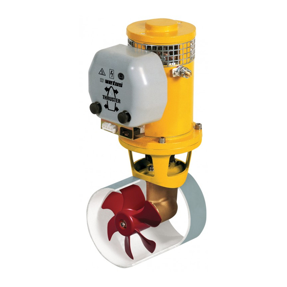
55 kgf
ø 150 mm
Copyright © 2006 Ve tus de n O uden n.v. Schieda m Holla nd
Bedieningshandleiding en
installatieinstructies
Operation manual and
installation instructions
Bedienungshandbuch und
Einbauanleitung
Manuel d'utilisation et
instructions d'installation
Manual de manejo y
instrucciones de instalación
Manuale per l'uso e
istruzioni per l'installazione
02-03-2006 11:50:03
02-03-2006 11:50:03
Werbung
Inhaltsverzeichnis
Fehlerbehebung

Verwandte Anleitungen für Vetus BOW5524A


Inhaltszusammenfassung für Vetus BOW5524A
- Seite 1 Bedieningshandleiding en installatieinstructies Operation manual and installation instructions Bedienungshandbuch und Einbauanleitung Manuel d’utilisation et instructions d’installation Manual de manejo y instrucciones de instalación Manuale per l’uso e istruzioni per l’installazione 55 kgf ø 150 mm Copyright © 2006 Ve tus de n O uden n.v. Schieda m Holla nd 020522.08.indd I 020522.08.indd I 02-03-2006 11:50:03...
-
Seite 2: Inhaltsverzeichnis
Inhoud Contents Inleiding Introduction Veiligheid Safety Gebruik Installatieinstructies Installation instructions Installatie aanbevelingen Installation recommendations Inbouw Installation Stroomverzorging The power supply Elektrische installatie Electrical installation Onderhoud Maintenance Storingen Trouble shooting Technische gegevens Technical data Inbouwvoorbeelden Installation examples Elektrisch schema Wiring diagram Hoofdafmetingen Principal dimensions Inhalt... -
Seite 3: Inleiding
NEDERLANDS Inleiding Veiligheid Afhankelijk van de windvang, de waterverplaatsing en de vorm WAARSCHUWING! van het onderwaterschip zal de door de boegschroef geleverde stuwkracht op ieder schip een verschillend resultaat geven. Let bij het gebruik van de boegschroef op het gevaar voor zwemmers of lichte bootjes welke zich in de onmiddelijke De nominaal opgegeven stuwkracht is alleen haalbaar onder nabijheid van de boegschroefbuis-uitstroomopeningen... -
Seite 4: Installatieinstructies
Wij raden de installatie van 2 boegschroeven in één (1) tunnel- buis af; er wordt geen verdubbeling van de stuwkracht bereikt! Deze installatie instructie geeft richtlijnen voor de inbouw van de Bij het kiezen van de Vetus boegschroeven ‘BOW5512A’ en ‘BOW5524A’. positie waar de tunnel- buis wordt... -
Seite 5: Overgang Van Tunnelbuis Naar Scheepsromp
NEDERLANDS Overgang van tunnelbuis naar scheepsromp Indien de overgang van tunnel- buis op scheepsromp met een schuine zijde wordt uitgevoerd dient deze volgens de tekening De wijze waarop de tunnelbuis overgaat in de scheeps- te worden uitgevoerd. romp is van grote invloed op de door de boegschroef Maak de schuine zijde (C) 0,1 geleverde stuwkracht en op de rompweerstand tijdens de à... -
Seite 6: Inbouw
Bij een stalen of aluminium tunnelbuis kan vermindering Polyester tunnelbuis: van corrosie worden bereikt Hars: Het voor de polyester tunnelbuis toegepaste hars is door het volledig geïsoleerd isophtaalzure polyesterhars (Norpol PI 2857). Voorbehandeling: De buitenzijde van de buis moet wor- opstellen van het staartstuk in de tunnelbuis. -
Seite 7: Montage Staartstuk En Tussenflens
NEDERLANDS Montage staartstuk en tussenflens Eindmontage Verwijder de schroef. Vet de schroefas in met ‘out- board gear grease’ en mon- teer de schroef. De schroef dient nu rondom Breng één pakking aan tus- minimaal 1,5 mm van de tun- sen staartstuk en tunnelbuis, nelbuiswand vrij te lopen. -
Seite 8: Stroomverzorging
Vetus kan een serie/parallel-schakelaar leveren die reeds is een ankerlier op deze accu’s aan. voorzien van de benodigde hulprelais om een eenvoudige aan- sluiting op de Vetus boegschroef te kunnen realiseren, Vetus De wijze waarop de boegschroef bediend moet worden blijft na art. code: BPSP . -
Seite 9: Elektrische Installatie
NEDERLANDS Electrische installatie Breng tus- Let op dat bij het aansluiten van elektrische kabels senkabel tussen geen andere elektrische delen los komen. boegschroef bedieningspaneel Controleer na 14 dagen alle elektrische verbindingen. aan in het schip Ten gevolge van temperatuurschommelingen kunnen en steek de ste- elektrische delen (bijvoorbeeld bouten en moeren) los kerverbindingen... -
Seite 10: Onderhoud
BP1132 BP1133 12 V 24 V Voor accu-onderhoud dienen de instructies van de acculeve- = 14 mm rancier te worden geraadpleegd. VETUS accu’s zijn onder- min. houdsvrij. BP1134 BP1135 12 V 24 V Raadpleeg Vetus voor andere motortypen dan bovenge- noemd. -
Seite 11: Storingen
NEDERLANDS Storingen Electromotor draait helemaal niet. - Controleer of de hoofdschakelaar ‘AAN’ staat. - Controleer of de stuurstroomzekering is doorgebrand. - Controleer of de hoofdstroomzekering is doorgebrand. In alle bovenstaande gevallen brandt de ‘POWER’ indicatielamp niet. Controleer of de schroef te draaien is. Tussen de schroef en de tunnel kan b.v. -
Seite 12: Technische Gegevens
Technische gegevens Type BOW5512A BOW5524A Electromotor Type omkeerbare gelijkstroommotor Spanning 12 V = 24 V = Stroom 375 A 205 A Afgegeven vermogen 3 kW Toerental 3400 omw/min Inschakelduur S2 - 4 min. Bescherming IP20 Motoren zijn conform CE (89/336/EEC, EMC - EN60945) -
Seite 13: Introduction
ENGLISH Introduction Safety The thrust given by the bow thruster will vary from vessel to ves- WARNING! sel depending on the effect of the wind, the water displacement and the shape of the underwater hull. When using the bow thruster watch out for swimmers or light boats which could be in the near vicinity of the bow The nominal thrust quoted can only be achieved under the most thruster tunnel jet openings. -
Seite 14: Installation Instructions
These installation instructions give guidelines for fitting the into account for optimum Vetus bow thrusters ‘BOW5512A’ and ‘BOW5524A’. performance: • The distance A shown The standard of fitting determines the reliability of the bow in the drawing must thruster. - Seite 15 ENGLISH ENGLISH Connection of thrust tunnel to ship’s hull If the connection of the thrust tunnel and the ship’s hull is to be made with a sloped side, it should be executed in accord- The manner, in which the thrust tunnel is connected to the ance with the drawing.
-
Seite 16: Installation Of The Thrust Tunnel
Corrosion of a steel or alu- minium thrust tunnel can be Polyester thrust tunnel: reduced by ensuring that Resin: The resin used for the polyester thrust tunnel is the tail piece is completely Isophtalic polyester resin (Norpol Pl 2857). insulated from the thrust- Pre-treatment: The outside of the tunnel must be rough- tunnel. -
Seite 17: Final Assembly
ENGLISH Installation of tail piece and intermediate Final assembly flange Remove the propeller. Grease the propeller shaft with ‘outboard gear grease’ and install the propeller. The propeller should run a Install one (1) gasket between minimum of 1.5 mm free the tail piece and the thrust of the thrust tube wall, all tunnel. -
Seite 18: The Power Supply
A main switch and fuse must be fitted in the ‘plus’ cable. A Vetus battery switch is suitable here. The fuse protects the bow thruster against overvoltage and at the same time protects the vessel’s wiring against short-circuits. -
Seite 19: Electrical Installation
ENGLISH ENGLISH Electrical installation control Make sure that no other electrical parts come loose cable between the when connecting the electric cables. bow thruster and the control panel Check all electrical connections after 14 days. Electrical through the ves- parts (such as bolts and nuts) may come loose as a sel and connect result of fluctuations in temperature. -
Seite 20: Maintenance
= 14 mm min. BP1134 BP1135 12 V 24 V Consult with Vetus for motor types other than those given here. 020522.08 Operation manual and installation instructions Bow thruster 55 kgf, ø 150 mm 020522.08.indd 18 020522.08.indd 18 02-03-2006 11:50:13... -
Seite 21: Trouble Shooting
ENGLISH Trouble shooting Electric motor does not operate - Check that the battery main switch is ‘ON’. - Check whether the control panel fuse has burnt out. - Check if the main fuse has burnt out. In all the above cases the ‘POWER’ indicator lamp will not be on. -
Seite 22: Technical Data
Technical data Type BOW5512A BOW5524A Electric motor Type reversible DC motor Voltage 12 V DC 24 V DC Current 375 A 205 A Rated output 3 kW No. of revolutions 3400 rpm Rating S2 - 4 min. Protection IP20 Motors conform to CE (80/336/EEC, EMC - EN60945) -
Seite 23: Einleitung
DEUTSCH Einleitung Sicherheitsbestimmungen Je nach Takelage, Wasserverdrängung und Unterwasser- WARNUNG! schifform führt die Antriebskraft durch die Bugschraube auf jedem Schiff zu anderen Ergebnissen. Achten Sie bei Benutzung der Bugschraube auf die Gefahr für Schwimmer und kleine Boote, die sich in unmit- Die angegebene Nennantriebskraft ist nur unter optimalen telbarer Nähe der Bugschraubenrohrausström-öffnungen Umständen erreichbar:... -
Seite 24: Einbauanleitung
Wir raten davon ab, 2 Bugschrauben in einem (1) Tunnelrohr einzu-bauen. Eine Verdoppelung der Antriebskraft wird dadurch nicht erreicht! Diese Einbauanleitung enthält Richtlinien für den Einbau der Vetus Bugschrauben ‘BOW5512A’ und ‘BOW5524A’. Bei der Platzbestimmung Tunnelrohrs soll Die Einbauqualität ist maßgeblich für die Zuverlässigkeit der für die bestmöglichen... -
Seite 25: Übergang Vom Tunnelrohr Zum Schiffsrumpf
DEUTSCH Übergang vom tunnelrohr zum schiffsrumpf Wenn Übergang Tunnelrohr zum Schiffsrumpf mit abgeschrägter Seite verse- hen wird, so soll die Ausführung Die Art und Weise worauf das Tunnelrohr zum Schiffsrumpf laut obenstehender Zeichnung übergeht, beeinflusst sehr den von der Bugschraube durchgeführt werden. -
Seite 26: Einbau
Korrosion eines Stahl- oder Aluminium-Tunnelrohrs kann Polyester-Tunnelrohr: verringert werden durch voll- Harz: Für das Polyester-Tunnelrohr wird isophtal-saures ständig isolierte Montage Polyesterharz (Norpol PI 2857) benutzt. des Unterwasserteils in das Vorbehandlung: Die Außenseite der Rohre ist aufzurau- Tunnelrohr. hen. Die gesamte, obere Schicht bis zum Glasfibergewebe ACHTUNG: Die mitgeliefer- entfernen, dafür eine Schleifscheibe benutzen. -
Seite 27: Befestigung Des Unterwasserteils Und Des Zwischenflansches
DEUTSCH Befestigung des Unterwasserteils und des Endmontage Zwischenflansches Entferne die Schraube. Die Schraubenwelle mit ‘out- board gear grease’ einfetten und die Schraube montieren. Zwischen Unterwasserteil und Zwischen Tunnelrohrwand Tunnelrohr eine (1) Dichtung und Schraube muß sich anbringen und dabei - zwi- nun ringsherum ein freier schen dem Unterwasserteil Spielraum von mindestens... -
Seite 28: Stromversorgung
Akkukapazitäten und Bugschraube abgestimmt sein. Siehe Tabelle. Akkuanschlußkabeln. Siehe Einbauanleitungen. Bei Wir empfehlen wartungsfreie Schiffsakkus von Vetus. Sie sind in Verwendung erheblich größerer Akkus in Kombination folgenden Größen lieferbar: 55 Ah, 70 Ah, 108 Ah, 120 Ah, 143 mit sehr kurzen Akkuanschlußkabeln mit einem erheb-... -
Seite 29: Elektrische Installation
DEUTSCH Elektrische Installation Zwischen- Achten Sie darauf, dass sich beim Anschluss von kabel zwischen Elektrokabeln keine anderen elektrischen Teile lösen. Bugschraube und A r m a t u r e n b r e t t Kontrollieren Sie nach 14 Tagen alle elektrischen verlegen Verbindungen. -
Seite 30: Wartung
) Art.Nr. für einen Kohlebürstensatz (4 Stück). mit ‘Outboard gear grease’ einfetten und die Schraube wieder an der Achse einbau- Bei der Akku-Wartung sind die Anweisungen des Akkulieferanten zu beachten. VETUS Akkus sind wartungsfrei. BP1132 BP1133 12 V 24 V = 14 mm min. -
Seite 31: Störungen
DEUTSCH Störungen Der Elektromotor läuft überhaupt nicht. - Steht der Hauptschalter auf ‘AN’? - Ist die Steuerstromsicherung durchgebrannt? - Ist die Hauptstromsicherung durchgebrannt? In allen diesen Fällen leuchtet die ‘POWER’-Anzeige nicht. Kontrollieren Sie, ob die Schraube sich dreht. Zwischen Schraube und Tunnel kann z.B. ein Stück Holz gelangt sein. Der Elektromotor läuft langsam. -
Seite 32: Technische Daten
Technische daten BOW5512A BOW5524A Electromotor umkehrbarer Gleichstrommotor Spannung 12 V = 24 V = Strom 375 A 205 A Leistung 3 kW Drehzahl 3400 U/min Einschaltdauer S2 - 4 min. Sicherung IP20 Motoren sind CE-konform (80/336/EEC, EMC - EN60945) Übertragung Zahnräder... -
Seite 33: Introduction
FRANÇAIS Introduction Sécurité Selon la prise de vent, le déplacement d’eau et la forme des AVERTISSEMENT! oeuvres vives, la force de propulsion fournie par l’hélice d’étra- ve entraînera un résultat différent sur chaque bateau. Lorsque vous utilisez l’hélice d’étrave, assurez-vous qu’il n’y a pas de nageurs ou de petits bateaux légers au voisi- La force de propulsion nominale indiquée n’est réalisable que nage immédiat des ouvertures de sortie du tube d’hélice... -
Seite 34: Instructions D'installation
Nous déconseillons l’installation de 2 hélices d’étrave dans un seul tunnel tubulaire ; on n’obtiendra pas une force de propul- sion double ! Les présentes instructions d’installation fournissent les directi- ves de montage pour les hélices d’étrave Vetus ‘BOW5512A’ et Afin d’obtenir ‘BOW5524A’. -
Seite 35: Adaption De La Tuyère À L'étrave
FRANÇAIS Adaption de la tuyère à l’étrave Quand la jonction entre la tuyè- re et la coque du bateau aura un côté chanfreiné, s’assurer que l’exécution sera faite selon La méthode de jonction de la tuyère à la coque du bateau, le croquis ci-dessus. -
Seite 36: Installation De La Tuyère
La corrosion d’une tuyère en acier ou en aluminium Tuyère en polyester: pourra être réduite par une Résine: La résine utilisée pour la tuyère en polyester est installation entièrement iso- une résine polyester isophtalique (Norpol PI 2857). lée de l’embasse dans la Traitement préalable: L’extérieur de la tuyère doit être tuyère. -
Seite 37: Montage Final
FRANÇAIS Montage de l’embase et de la bride interme- Montage final diaire Dépose l’hélice. Graisser l’arbre d’hélice avec de l’ ‘outboard gear grease’ et installer l’hélice. Poser un joint entre l’em- L’hélice doit à présent tourner base et la tuyère. Mettre du librement à... -
Seite 38: L'alimentation Électrique
Nous recommandons les batteries pour bateaux sans entretien rie qui sont recommandés, voir ‘Instructions d’installa- de Vetus ; elles sont disponibles dans les modèles suivants: tion’. L’emploi de batteries sensiblement plus grosses 55 Ah, 70 Ah, 108 Ah, 120 Ah, 143 Ah, 165 Ah, 200 Ah et associé... -
Seite 39: Installation Électrique
FRANÇAIS Installation électrique Monter le câble En raccordant les câbles électriques, attention à ne i n t e r m é d i a i r e pas détacher d’autres composantes électriques. entre l’hélice d’étrave et le pan- Après deux semaines, contrôler toutes les connexions neau de comman- électriques. -
Seite 40: Entretien
‘outboard gear grease’ et montez à nouveau l’hélice sur l’arbre. Pour l’entretien de la batterie, veuillez consulter les instructions données par le fournisseur de la batterie. Les batteries VETUS ne nécessitent pas d’entretien. BP1132 BP1133 12 V... -
Seite 41: Pannes
FRANÇAIS Pannes Le moteur électrique ne fonctionne pas du tout - Vérifiez si l’interrupteur principal est en position ‘MARCHE’ - Vérifiez si le fusible de courant de commande n’a pas fondu - Vérifiez si le fusible de courant principal n’a pas fondu. Dans tous les cas ci-dessus, la lampe ‘POWER’... -
Seite 42: Renseignements Techniques
Renseignements techniques Type BOW5512A BOW5524A Moteur électriques Type moteur réversible, courant continu Voltage 12 V CC 24 V CC Consommation 375 A 205 A Puissance disponible 3 kW Tours minute 3400 t/min Etalonage S2 - 4 min. Protection IP20 Les moteurs sont conformes à CE (80/336/CEE, EMC - EN60945) -
Seite 43: Introducción
ESPAÑOL Introducción Seguridad En función de la amurada, el desplazamiento de agua y la ¡PRECAUCIÓN! forma subacuática de la embarcación, la fuerza de propulsión generada por la hélice de proa dará un resultado distinto en Al utilizar la hélice de proa prestar atención al peligro que cada embarcación. -
Seite 44: Instrucciones De Instalación
(1); ¡no se logra ninguna duplicación de la fuerza de propulsión! Estas instrucciones de instalación son una guía para la incorpo- ración de las hélices de proa ‘BOW5512A’ y ‘BOW5524A’. A la hora de determinar la posición donde insta- La calidad de la incorporación determina la fiabilidad de la... -
Seite 45: Acoplamiento Del Conducto De Propulsión Al Casco
ESPAÑOL Acoplamiento del conducto de propulsión al Si se realizará la conexión del casco conducto al casco con un lado oblicuo, éste se debe de reali- zar de acuerdo con el croquis. La forma en que el conducto de propulsión se acopla al Hacer el lado oblicuo (C) 0,1 casco tiene gran influencia sobre la fuerza de propulsión a 0,15 x D de largo y asegurar... -
Seite 46: Incorporación
La corrosión de un conduc- to en acero o en aluminio se Conducto de propulsión de poliéster: puede reducir por medio de Resina: La resina empleada para el conducto de propul- una instalación enteramente sión de poliéster es resina de poliéster de ácido de isoftal aislada de la cola dentro del (Norpol PI 2857). -
Seite 47: Instalación De La Parte Posterior Y La Brida Intermedia
ESPAÑOL Instalación de la parte posterior y la brida Instalación final intermedia Retirar la hélice. Engrasar el eje de la hélice con ‘outboard gear grease’ y montar la hélice. Montar una junta entre la Ahora la hélice debe girar parte posterior y el conducto libremente en toda su vuelta de propulsión, aplicando - como mínimo a 1,5 mm con... -
Seite 48: El Suministro De Corriente
En el ‘cable positivo’ se integrarán un interruptor central y un fusible. Un interruptor muy adecuado es el interruptor de bate- ría Vetus. El fusible protege la hélice de proa contra sobrecar- gas así como la red de a bordo contra cortocircuitos. -
Seite 49: Instalación Eléctrica
ESPAÑOL Instalación eléctrica Montar el cable Conecte los cables eléctricos prestando mucha aten- intermedio entre ción para evitar que se aflojen componentes eléctri- la hélice de proa y cos. el tablero de man- dos en la embar- Compruebe todas las conexiones eléctricas cada 14 cación y enchufar días. -
Seite 50: Mantenimiento
BP1134 BP1135 12 V 24 V Consúltese a Vetus para otros tipos de motor que los arriba indicados. 020522.08 Manual de manejo y instrucciones de instalación para la hélice de proa 55 kgf, ø 150 mm 020522.08.indd 48 020522.08.indd 48... -
Seite 51: Fallos
ESPAÑOL Fallos El electromotor no funciona en absoluto - Controlar si el interruptor central está activado en ‘ON’. - Controlar si se ha fundido el fusible de la corriente de nave- gación. - Controlar si se ha fundido el fusible de la corriente principal. En todos los casos arriba indicados no se enciende el indicador luminoso ‘POWER’. -
Seite 52: Especificaciones Técnicas
Especificaciones técnicas Tipo BOW5512A BOW5524A Electromotor Tipo motor de corriente continuo reversible Tensión 12 V = 24 V = Corriente 375 A 205 A Potencia nominal 3 kW Número de revoluciones 3400 rev/min Duración de activación S2 - 4 min. -
Seite 53: Introduzione
ITALIANO Introduzione Sicurezza In base alla superficie laterale esposta al vento, alla stazza e alla ATTENZIONE! forma dell’opera viva, la propulsione generata dall’elica di prua darà un risultato diverso su ogni imbarcazione. Durante l’uso dell’elica di prua fare attenzione ad eventua- li ragnanti o piccole imbarcazioni che potrebbero trovarsi La propulsione nominale è... -
Seite 54: Instruzioni Per L'installazione
Sconsigliamo l’installazione di 2 eliche di prua in un solo (1) tunnel; la propulsione non raddoppia! Queste istruzioni si riferiscono la montaggio delle eliche di prua Al momento di scegliere Vetus ‘BOW5512A’ e ‘BOW5524A’. la posizione del tunnel, per un risultato ottimale, La qualità dell’installazione è determinante per l’affidabilità del- è... -
Seite 55: Montaggio Del Tunnel Allo Scafo
ITALIANO Montaggio del tunnel allo scafo Se il collegamento del tunnel allo scafo è stato eseguito con un lato obliquo, quest’ultimo va eseguito seguendo il disegno. Il modo in cui il tunnel è collegato allo scafo influenza La lunghezza del lato obliquo enormemente la propulsione dell’elica e l’attrito esercitato (C) deve essere compresa fra i dallo scafo durante la navigazione normale. -
Seite 56: Installazione Del Tunnel
La corrosione di un tunnel in acciaio o alluminio può Tunnel in poliestere: essere ridotta tramite il mon- Resina: La resina utilizzata per il tunnel in poliestere è taggio isolato del piedino resina poliestere a base di acido isoftalico (Norpol PI nel tunnel. -
Seite 57: Montaggio Del Piedino E Della Flangia Intermedia
ITALIANO Montaggio del piedino e della flangia inter- Assemblaggio finale media Togliere l’elica. Lubrificare l’albero dell’elica con dell’olio per motori fuori- bordo e montare l’elica. Installare la guarnizione fra Adesso la distanza fra l’elica la coda e il tunnel. Fra la e la parete del tunnel deve coda e la guarnizione e fra la essere di almeno 1,5 mm... -
Seite 58: La Scelta Della Batteria
10% della tensione totale, vedi tabella. Al ‘cavo-positivo’ è necessario aggiungere un interruttore su un fusibile. Molto adatto a questo scopo è l’interruttore per batteria VETUS. Il fusibile protegge l’elica dal sovraccarico e protegge la rete di bordo dal corto circuito. Fusibile Per l’elica di prua può... -
Seite 59: Collegamento Elettrico
ITALIANO Collegamento elettrico Installare la pro- Assicuratevi che quando collegate i cavi elettrici non lunga fra l’elica di si scolleghino altre parti elettriche. prua e il pannello di comando all’in- Dopo 14 giorni, controllate tutti i collegamenti elettrici. terno dell’imbar- Alcune parti elettriche (come dadi e bulloni) possono cazione e colle- allentarsi a seguito delle escursioni termiche. -
Seite 60: Manutenzione
= 14 mm min. BP1134 BP1135 12 V 24 V Rivolgersi alla Vetus per motori di un tipo diverso da quelli indicati. 020522.08 Manuale per l’uso e instruzioni per l’installazione dell’elica di prua 55 kgf, ø 150 mm 020522.08.indd 58 020522.08.indd 58... -
Seite 61: Guasti
ITALIANO Guasti Il motore elettrico non gira - Controllare che l’interruttore principale sia su ‘ON’ (acceso). - Controllare se il fusibile della corrente di comando è brucia- - Controllare se il fusibile della corrente principale è bruciato. Nei suddetti casi la spia ‘POWER’ (accesso) è spenta. Controllare se l’elica si riesce a girare. -
Seite 62: Dati Tecnici
Dati tecnici Tipo BOW5512A BOW5524A Motore elettrico Tipo motore reversibile a corrente continua Tensione 12 V = 24 V = Corrente 375 A 205 A Potenza nominale 3 kW Nr. giri 3400 giri/min Durata di azionamento S2 - 4 min. -
Seite 63: Inbouwvoorbeelden
Inbouwvoorbeelden Einbaubeispiele Ejemplos de instalación Installation examples Exemples d’installation Esempi per l’installazione Opstelling 2 boegschroeven in catamaran Two bow thrusters fitted in a catamaran Einbau von 2 Bugschrauben in einem Katamaran Disposition de 2 hélices d’étrave sur un catamaran Ubicación de 2 hélices de proa en un catamarán Installazione di 2 eliche di prua su un catamarano Operation manual and installation instructions Bow thruster 55 kgf, ø... -
Seite 64: Elektrisch Schema
Elektrisch schema Schaltschema Esquema eléctrico Wiring diagram Circuit electrique Schema elettrico 3-10722 55/75/95/160/220 kgf 1 Hoofdzekering 1 Main fuse 1 Hauptsicherung 2 Hoofdschakelaar 2 Main switch 2 Hauptschalter 3 Stuurstroomzekering 3 Control current fuse 3 Steuerstromsicherung 4 Magneetschakelaar 4 Solenoid switch 4 Relais 5 Elektromotor 5 Electromotor... - Seite 65 1 Fusible principal 1 Fusible principal 1 Fusibile principale 2 Interrupteur principal 2 Interruptor principal 2 Interruttore principale 3 Fusible courant de commande 3 Fusible de circuito de control 3 Fusibile del circuito di comando 4 Contacteur solénoïde 4 Interruptor de solenoide 4 Interruttore solenoidale 5 Moteur électrique 5 Electromotor...
-
Seite 66: Hoofdafmetingen
Hoofdafmetingen Hauptabmessungen Dimensiones principales Principal dimensions Dimensions principales Dimensioni principali 1 : 10 020522.08 Operation manual and installation instructions Bow thruster 55 kgf, ø 150 mm 020522.08.indd 64 020522.08.indd 64 02-03-2006 11:50:33 02-03-2006 11:50:33... - Seite 67 Aantekeningen Notizen Anotaciones Remarks Remarques Note Operation manual and installation instructions Bow thruster 55 kgf, ø 150 mm 020522.08 020522.08.indd 65 020522.08.indd 65 02-03-2006 11:50:33 02-03-2006 11:50:33...
- Seite 68 FOKKERSTRAAT 571 - 3125 BD SCHIEDAM - HOLLAND - TEL.: +31 10 4377700 - TELEX: 23470 TELEFAX: +31 10 4372673 - 4621286 - E-MAIL: sales@vetus.nl - INTERNET: http://www.vetus.com Printed in the Netherlands 020522.08 03-06 020522.08.indd 66 020522.08.indd 66 02-03-2006 11:50:33...