Exsys EX-44072 Bedienungsanleitung
EX
EX-
EX
-
-
44072 /
44072 / EX
44072 / EX
EX-
-
-
44272
44272
44272
JUMPER SETTING & CONNECTORS
J6:
1 +5V
For aux power (JP2), J6 must be connected to pc power supply !
2 GND
3 GND
If not, the card wont work.
4 +12V
DB 9M:
Serial 9 Pin D-SUB connector
Pin
Signal
Pin
1
CDC
4
2
RXD
5
GROUND
3
TXD
6
HARDWARE INSTALLATION
If you are ready with the jumper settings, please proceed with the following installation
instructions. Because there are large differences between PC's, we can give you only a
general installation guide. Please refer to your computer's reference manual whenever
in doubt.
1. Turn off the power to your computer and any other connected peripherals.
2. Remove the mounting screws located at the rear and/ or sides panels of your Com-
puter and gently slide the cover off.
3. Locate an available expansion slot and remove its covers from the rear panel of your
computer. Make sure it is the right expansion slot for the card (see card description)
4. Align the card with the expansion slot, and then gently but firmly, insert the card.
Make sure the card is seated and oriented correctly. Never insert the card by force!
5. Then connect the card with a screw to the rear panel of the computer case.
6. Gently replace your computer's cover and the mounting screws.
DRIVER INSTALLATION
Windows 2000/ XP/ Vista/ 7/ 8
After starting Windows it recognizes a new "PCI Controller" and opens the hardware
assistant. Please choose manual installation and put the driver CD into your CD-ROM
drive. Now enter the Path "D:\IO\OXFORD2\" and then the directory of your operating
system into the box for the Path/Source and click at >next/continue<. Now Windows
searches for the drivers in the specified directory. Follow the hardware assistant and
finish the installation. If Windows recognizes other new devices repeat the above de-
scribed steps.
Attention! Restart your PC in any case after installing the drivers.
CHECK THE INSTALLED DRIVER
Click at Start<>Run< then enter "compmgmt.msc" and click at >OK<. In the windows
that opens select >Device Manager<. Under „Ports (COM and LPT)" you should find
a new „PCI Port" as sample (COM3). If you see this or similar entries the card is
installed correctly.
CHANGE PORT NUMBER
If you like to change the port number for example COM3 to COM5, open the >Device
Manager< click at >COM3<, >Settings< and then >Advance<. There you can change
between COM3 till COM256.
5
English
English
English
EX
EX-
EX
-
-
44072 / EX
44072 / EX
44072 /
DRIVER INSTALLATION
Windows Server 200x
After starting Windows it recognizes a new "PCI Controller" and opens the hardware
assistant. Please choose manual installation and put the driver CD into your CD-Rom
drive. Now enter the Path "D:\IO\OXFORD2\" and then the directory of your operating
system for Server 2000: "2000", for Server 2003: "XP32" or "XP64", for Server 2008:
„Vista32" or „Vista64" and for Server 2008 R2: „Win7_8_32bit" or „Win7_8_64bit"
into the box for the Path/Source and click at >next/continue<. Now Windows searches
Signal
Pin
Signal
for the drivers in the specified directory. Follow the hardware assistant and finish the
installation. If Windows recognizes other new devices repeat the above described
DTR
7
RTS
steps.
8
CTS
Attention! Restart your PC in any case after installing the drivers.
DSR
9
RI
CHECK THE INSTALLED DRIVER
Click at Start<>Run< then enter "compmgmt.msc" and click at >OK<. In the windows
that opens select >Device Manager<. Under „Ports (COM and LPT)" you should find
a new „PCI Port" as sample (COM3). If you see this or similar entries the card is
installed correctly.
CHANGE PORT NUMBER
If you like to change the port number for example COM3 to COM5, open the >Device
Manager< click at >COM3<, >Settings< and then >Advance<. There you can change
between COM3 till COM256.
LINUX
The drivers are located in the following folder on our driver CD:
"D:\IO\OXFORD2\LINUX"
Because each individual distribution and kernel version of Linux is different, sadly we
cant provide a installation instruction. Please refer to the installation manual for stan-
dard I/O ports from your Linux version! In some newer versions of Linux the card will
even be installed automatically after starting Linux.
EX-
-
-
44272
44272
44272
6
English
English
English
Bedienungsanleitung
Bedienungsanleitung
Vers. 1.4 / 02.07.13
AUFBAU
S2: 9 Pin Stecker
Serieller Anschluss
S1: 9 Pin Stecker
Serieller Anschluss
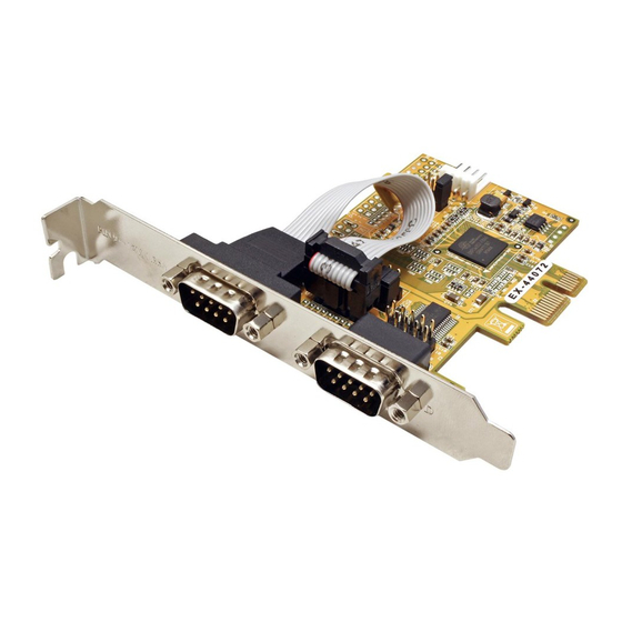
BESCHREIBUNG & TECHNISCHE DATEN
Die EX-44072 / EX-44272 ist eine PCI-Express serielle RS-232 Karte mit 2 seriellen
FIFO 16C95x Ports, für den Anschluss von High-Speed seriellen RS-232 Peripherie
Geräten (z.B. Terminal, Modem, Plotter usw.). Der serielle PCI-Express Bus unterstützt
dabei optimal die Leistung des schnellen 16C95x Chipset mit 128byte FIFO Cache. Die
EX-44072 / EX-44272 gewährleistet so eine sichere Datenübertragung und exzellente
Performance von bis zu 921KBaud/s für jedes angeschlossene Gerät! Sie unterstützt
alle PCI-Express Slots von x1 bis x16. Es ist nicht möglich die I/O Adressen und Inter-
rupts manuell einzustellen, da die Einstellungen der Karte vom System (BIOS) und
beim installieren des Betriebssystems automatisch vorgenommen werden. Mit dem
Jumper JP2 & JP3 können Sie 12V oder 5V auf Pin 9 des seriellen Anschlusses leiten.
Achten Sie bitte darauf dass die Angeschlossenen Geräte dies auch unterstützen. Bei
der EX-44272 handelt es sich um eine Low Profile Karte mit 8cm Slotblech.
Kompatibilität:
PCI-Express x1 bis x16
Betriebssysteme:
Windows 2000/ XP/ Vista/ 7/ 8/ Server 200x/ Linux
Anschlüsse:
2x 9 Pin Seriell D-Sub Stecker
Lieferumfang:
EX-44072 oder EX-44272, Treiber CD, Anleitung
Zertifikate:
CE CE
CE / FCC / RoHS / WEEE
CE
JUMPER EINSTELLUNG & ANSCHLÜSSE
JP3:
DIS
= Am Pin 9 liegt das Standard Signal RI (Ring Indicator)
(Werkseinstellung)
DIS PWR
PWR
= Am Pin 9 kann jetzt eine Spannung von DC5V oder DC12V
eingestellt werden
S1
Die Einstellung der Spannung nehmen Sie mit dem JP2 vor. Dies sollte
S2
aber bei Standard Anwendungen nicht verstellt werden.
Wenn Sie den Jumper JP3 auf PWR gesetzt haben, können Sie mit
JP2:
dem Jumper JP2 den Spannungswert einstellen. Es gibt 3 verschiedene
Spannungsquellen.
AUX5V
(Nur in Verbindung mit JP3 auf PWR!!!)
AUX12V
PCI12V
AUX 5V = 5Volt vom PC-Netzteil
AUX 12V = 12Volt vom PC-Netzteil
PCI 12V = 12Volt vom Mainboard (STANDARD)
JP2: Jumper für die Stromquelle
(Netzteil oder PCI-Express Bus)
J6: Anschluss für Strom
vom PC Netzteil
JP3: Power auf 9 Pin
Stecker Ein/Aus
J1: Interner Serieller
Anschluss
DE97424562 / WHQL
1

Verwandte Anleitungen für Exsys EX-44072


Inhaltszusammenfassung für Exsys EX-44072
- Seite 1 4. Align the card with the expansion slot, and then gently but firmly, insert the card. Die EX-44072 / EX-44272 ist eine PCI-Express serielle RS-232 Karte mit 2 seriellen Because each individual distribution and kernel version of Linux is different, sadly we Make sure the card is seated and oriented correctly.
- Seite 2 Beachten Sie das die Karte korrekt eingesteckt wird und das kein Kurzschluss ent- Da sich die einzelnen Distributionen und Kernelversionen sehr voneinander unterschei- for the PCI Express Bus. The EX-44072 / EX-44272 provides two 9 pin high speed RS- steht. Wenden Sie bitte keine Gewalt an um die Karte einzustecken! den, können wir Ihnen leider keine Installationsanweisung zur Verfügung stellen.