Exsys EX-44094-2 Bedienungsanleitung
Verfügbare Sprachen
Verfügbare Sprachen
EX
EX-
EX
-
-
44094
44094
44094-
-
-
2
2
2
JUMPER SETTING & CONNECTORS
JP6:
This jumper JP6 is used to control the baud rate clock input of the
UARTs. There are 2 settings.
LOW
= The clock is 1.8432MHz, the maximum baud rate is
115.2Kbps.
HI
= The clock is 14.7456MHz, the maximum baud rate is
LOW
HI
921.6Kbps. (Factory setting)
NOTE: If you use the HI clock setting then you must change the com
port settings in the device manager! Please select detect crystal auto-
matically and set the clock value for your application.
J7:
1 +5V
For aux power (JP3), J7 must be connected to pc power supply!
2 GND
If not, the card won't work.
3 GND
4 +12V
DB9M:
Serial 9 Pin D-SUB connector
Pin
Signal
Pin
1
CDC
4
2
RXD
5
GROUND
3
TXD
6
HARDWARE INSTALLATION
If you are ready with the jumper settings, please proceed with the following installation instructions.
Because there are large differences between PC's, we can give you only a general installation
guide. Please refer to your computer's reference manual whenever in doubt.
1.
Turn off the power to your computer and any other connected peripherals.
2.
Remove the mounting screws located at the rear and/ or sides panels of your Computer and
gently slide the cover off.
3.
Locate an available expansion slot and remove its covers from the rear panel of your com-
puter. Make sure it is the right expansion slot for the card (see card description)
4.
Align the card with the expansion slot, and then gently but firmly, insert the card. Make sure
the card is seated and oriented correctly. Never insert the card by force!
5.
Then connect the card with a screw to the rear panel of the computer case.
6.
Gently replace your computer's cover and the mounting screws.
DRIVER INSTALLATION
Windows 9x/ ME/ 2000/ XP/ Vista/ 7/ 8
After starting Windows it recognizes a new "PCI Controller" and opens the hardware assis-
tant. Please choose manual installation and put the driver CD into your CD-ROM drive. Now
enter the Path "D:\IO\OXFORD\" and then the directory of your operating system into the box
for the Path/Source and click at >next/continue<. Now Windows searches for the drivers in
the specified directory. Follow the hardware assistant and finish the installation. If Windows
recognizes other new devices repeat the above described steps. Attention! Restart Windows
in any case after installing the drivers.
CHECK THE INSTALLED DRIVER
Click at Start<>Run< then enter "compmgmt.msc" and click at >OK<. In the windows that
opens select >Device Manager<. Under „Ports (COM and LPT)" you should find a new „PCI
Port" as sample (Com3). If you see this or similar entries the card is installed correctly.
CHANGE PORT NUMBER
If you like to change the port number for example COM3 to COM5, open the >Device Manager<
click at >COM3<, >Settings< and then >Advance<. There you can change between COM3 to
COM256.
5
English
English
English
EX
EX-
EX
-
-
44094
44094
44094-
DRIVER INSTALLATION
Windows Server 200x
After starting Windows it recognizes a new "PCI Controller" and opens the hardware assis-
tant. Please choose manual installation and put the driver CD into your CD-ROM drive. Now
enter the Path "D:\IO\OXFORD\" and then the directory of your operating system for Server
2000 "2000", for Server 2003 "XP32" or "XP64", for Server 2008 „Vista32" or „Vista64" and
for Server 2008 R2 „Win7_8_32bit" or „Win7_8_64bit" into the box for the Path/Source and
click at >next/continue<. Now Windows searches for the drivers in the specified directory.
Follow the hardware assistant and finish the installation. If Windows recognizes other new
devices repeat the above described steps. Attention! Restart Windows in any case after
installing the drivers.
CHECK THE INSTALLED DRIVER
Click at Start<>Run< then enter "compmgmt.msc" and click at >OK<. In the windows that
opens select >Device Manager<. Under „Ports (COM and LPT)" you should find a new „PCI
Port" as sample (Com3). If you see this or similar entries the card is installed correctly.
CHANGE PORT NUMBER
If you like to change the port number for example COM3 to COM5, open the >Device Manager<
click at >COM3<, >Settings< and then >Advance<. There you can change between COM3 to
COM256.
Signal
Pin
Signal
DTR
7
RTS
Windows NT 4.0
8
CTS
Start Windows NT and insert the driver CD into your CD-ROM drive (for example D:). Click at
>Start< >Run< and enter „D:\IO\OXFORD\NT4\Install_Serial.exe" then click >OK<. Windows
DSR
9
RI
NT will now start the setup program and install the driver. Please Restart Windows NT after
installing the drivers.
CHECK THE INSTALLED DRIVER
Click at >Start< >Programs< >Administrative
Diagnostics< then click at >Resource< >IRQ<. Here you should find the entry „09
PCI". Then click at >I/O-Port< here you should see the entries „D400-D407 oxser
„D800-D802
addresses can change depends which system and card is installed. If you see these or similar
entry's the card is installed correctly.
LINUX
There are no drivers available for Linux, but the card is supported by the most versions of
Linux. Because each individual distribution and kernel version of Linux is different, sadly we
cant provide a installation instruction. Please refer to the installation manual for standard I/O
ports from your Linux version! In some newer versions the card will even be installed automati-
cally after starting Linux.
-
-
2
2
2
Tools[Common]< >Windows
oxser
0
PCI" and „DC00-DC1F oxser 0 PCI"
for the ports. The I/O
6
English
English
English
Bedienungsanleitung
Bedienungsanleitung
Vers. 1.2 / 13.06.14
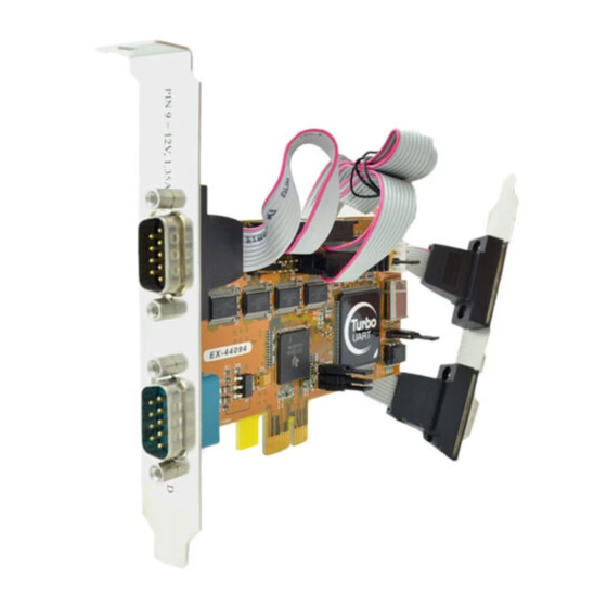
AUFBAU
JP2: Power auf 9 Pin Stecker Ein/Aus
S2: 9 Pin Stecker
Serieller
Anschluss
S4: 9 Pin Stecker
Serieller
Anschluss
S3: 9 Pin Stecker
Serieller Anschluss
S1: 9 Pin Stecker
Serieller Anschluss
BESCHREIBUNG & TECHNISCHE DATEN
NT-
Die EX-44094-2 ist eine PCI-Express serielle RS-232 Karte mit 4 seriellen FIFO 16C95x Ports,
oxser 0
für den Anschluss von High-Speed seriellen RS-232 Peripherie Geräten (z.B. Terminal, Mo-
0
PCI"
dem, Plotter usw.). Der serielle PCI-Express Bus unterstützt dabei optimal die Leistung des
schnellen 16C95x Chip-Sets mit 128byte FIFO Cache. Die Karte gewährleistet so eine sichere
Datenübertragung und exzellente Performance von bis zu 921KBaud/s für jedes angeschlos-
sene Gerät! Sie unterstützt alle PCI-Express Slots von x1 bis x16. Es ist nicht möglich die I/O
Adressen und Interrupts manuell einzustellen, da die Einstellungen der Karte vom System
(BIOS) und beim installieren des Betriebssystems automatisch vorgenommen werden. Mit dem
Jumper JP6 können Sie vom Standard Quarz (1.843MHz) auf den hohen (14.7456MHz) Quarz
umschalten. Beachten Sie bitte falls Sie mit dem hohen Quarz arbeiten, dass die Peripheriege-
räte dies auch unterstützen. Im Gerätemanager muss ausserdem die richtige Teilung (Divisor)
und Geschwindigkeit manuell eingestellt werden!
Kompatibilität:
PCI-Express x1 bis x16
Betriebssysteme:
WIN 9x/ ME/ NT4.0/ 2000/ XP/ Vista/ 7/ 8/ Server 200x/ Linux
Anschlüsse:
4x 9 Pin Seriell D-SUB Stecker
Lieferumfang:
EX-44094-2, Treiber CD, Anleitung, Bügel mit 2x 9 Pin Kabel
Zertifikate:
CE CE CE CE / FCC / RoHS / WEEE
JUMPER EINSTELLUNG & ANSCHLÜSSE
JP2:
DIS
= Am Pin 9 liegt das Standard Signal RI (Ring Indicator) an.
(Werkseinstellung)
PWR
= Am Pin 9 kann jetzt eine Spannung von DC5V oder DC12V
eingestellt werden.
Die Einstellung der Spannung nehmen Sie mit dem JP3 vor. Dies sollte
aber bei Standard Anwendungen nicht verstellt werden.
JP3:
Wenn Sie den Jumper JP2 für auf PWR gesetzt haben, können Sie mit
dem Jumper JP3 den Spannungswert einstellen. Es gibt 3 verschiedene
Spannungsquellen.
AUX5V
(Nur in Verbindung mit JP2 auf PWR!!!)
AUX12V
PCI12V
AUX 5V = 5Volt vom PC-Netzteil
AUX 12V = 12Volt vom PC-Netzteil
PCI 12V = 12Volt vom Mainboard (Werkseinstellung)
JP3: Jumper für die
Stromquelle
(Netzteil oder
PCI-Express Bus)
J7: Anschluss für
Strom vom
PC Netzteil
JP6: Umschalter
Baudrate
JP5: UART Mode Einstellung
(Nur für Testzwecke)
J1-J4: Interne Serielle
Anschlüsse
DE97424562 / WHQL
1

Verwandte Anleitungen für Exsys EX-44094-2


Inhaltszusammenfassung für Exsys EX-44094-2
- Seite 2 DESCRIPTION & TECNICAL INFORMATION ÜBERPRÜFEN DER INSTALLIERTEN TREIBER The EX-44094-2 is a plug & play high-speed serial RS-232 expansion card for the PCI Express Wenn Sie die Karte installieren, beachten Sie bitte die folgenden Hinweise. Da es große Unter- Klicken Sie auf >Start<>Programme<>Verwaltung(Allgemein)<>Windows NT-Diagnose<...