Inhaltsverzeichnis
Werbung
Verfügbare Sprachen
Verfügbare Sprachen
Quicklinks
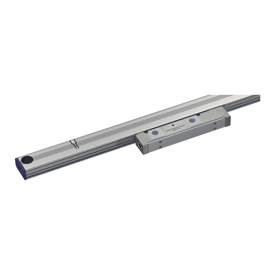
スケールセット / Scale set / Maßstabsatz
SR27A-AZ
, CH22
Series
Series
お買い上げいただき、ありがとうございます。
ご使用の前に、この取扱説明書を必ずお読みください。
ご使用に際しては、この取扱説明書どおりお使いください。
お読みになった後は、後日お役に立つこともございますので、必ず保管してください。
EU 機械指令に基づき、この取扱説明書の英文がオリジナルとなります。
Read all the instructions in the manual carefully before use and strictly follow them.
Keep the manual for future references.
The English version is the original manual according to the EU Machinery Directive.
Lesen Sie die ganze Anleitung vor dem Betrieb aufmerksam durch und folgen Sie beim Betrieb
des Geräts den Anweisungen.
Bewahren Sie diese Bedienungsanleitung zum späteren Nachlesen griff bereit auf.
Bei der englischsprachigen Version handelt es sich um die Original-Anleitung gemäß EU-
Maschinenrichtlinie.
取扱説明書 / Instruction Manual / Bedienungsanleitung
Werbung
Kapitel
Inhaltsverzeichnis

Verwandte Anleitungen für Magnescale CH22-XXXCS Serie


Inhaltszusammenfassung für Magnescale CH22-XXXCS Serie
- Seite 1 スケールセット / Scale set / Maßstabsatz SR27A-AZ , CH22 Series Series お買い上げいただき、ありがとうございます。 ご使用の前に、この取扱説明書を必ずお読みください。 ご使用に際しては、この取扱説明書どおりお使いください。 お読みになった後は、後日お役に立つこともございますので、必ず保管してください。 EU 機械指令に基づき、この取扱説明書の英文がオリジナルとなります。 Read all the instructions in the manual carefully before use and strictly follow them. Keep the manual for future references. The English version is the original manual according to the EU Machinery Directive. Lesen Sie die ganze Anleitung vor dem Betrieb aufmerksam durch und folgen Sie beim Betrieb des Geräts den Anweisungen.
- Seite 2 [For U.S.A. and Canada] THIS CLASS A DIGITAL DEVICE COMPLIES WITH PART15 OF THE FCC RULES AND THE CANADIAN ICES-003. OPERATION IS SUBJEC T TO THE FOLLOWING T WO CONDITIONS. (1) T H I S D E V I C E M AY N O T C A U S E H A R M F U L INTERFERENCE, AND (2) THIS DEVICE MUST ACCEPT ANY INTERFERENCE RECEIVED, INCLUDING INTERFERENCE THAT MAY...
- Seite 3 安全のために 当社の製品は安全に充分配慮して設計されています。しかし、操作や設置時にまちがった取 扱いをすると、火災や感電などにより死亡や大ケガなど人身事故につながることがあり、危 険です。また、機械の性能を落としてしまうこともあります。 これらの事故を未然に防ぐために、 安全のための注意事項は必ず守ってください。 操作や設置、 保守、点検、修理などを行なう前に、この「安全のために」を必ずお読みください。 警告表示の意味 このマニュアルでは、次のような表示をしています。表示内容をよく理解してから本文をお 読みください。 警告 この表示の注意事項を守らないと、火災や感電などにより死亡や大ケガなど人身事故につな がることがあります。 注意 この表示の注意事項を守らないと、感電やその他事故によりケガをしたり周辺の物品に損害 を与えることがあります。 注意を促す記号 注意 火災注意 感電注意 指はさみ注意 行為を禁止する記号 分解禁止 行為を指示する記号 プラグの取外し SR27A-AZ Series, CH22 Series...
- Seite 4 警告 守らないと 火災や感電の原因 仕様電源電圧以外で使用しない ➡ となる恐れがあり 表示された電源電圧以外での電圧で使用しないでください。 ます。 守らないと 濡れた手で取付作業をしない ➡ 感電の原因となる 濡れた手で取付作業をしないでください。 恐れがあります。 守らないと ケガの恐れがあり 分解しない ➡ ます。 ステータを開けて分解、改造しないでください。 *内部回路を破損する こともあります。 注意 守らないと 作業の安全を確保する ➡ ケガの恐れがあり 作業を行なう前には、装置の状況をよく確かめて作業の安 ます。 全を確保してください。 守らないと 火災やケガの原因 電源を入れたまま作業はしない ➡ 必ず電源などの駆動源を切ってから、作業をしてください。 となる恐れがあり ます。 守らないと 指はさみに注意する ➡ ケガの恐れがあり...
-
Seite 5: Inhaltsverzeichnis
目次 1. 製品概要 ..................1 1-1. 概要 ......................1 1-2. 特長 ......................1 1-3. システム構成 ....................1 1-4. 型名 ......................2 1-5. 機能安全 ......................3 1-6. 機械指令 ......................4 2. 取扱上の注意 ................5 3. 取付 ....................6 3-1. 各部の名称 ....................6 3-2. スケールユニットの取付 ................6 3-3. 接続ケーブルの取付 .................11 3-4. コントローラとの結線 ................12 3-5. - Seite 6 SR27A-AZ Series, CH22 Series...
-
Seite 7: 製品概要
1. 製品概要 1-1. 概要 本製品は、工作機械向けの位置検出装置です。シールド型高精度アブソリュートマグネスケー ルと接続ケーブルは、SIEMENS 社 DRIVE-CLiQ シリアル通信に対応しています。 1-2. 特長 ・ スケールユニットは鉄製のシールドケースを採用し、小型断面ながら高剛性を実現していま す。 ・ スケールユニットと接続ケーブルはコネクタにより分離されています。これによりスケール ユニットの取付作業とケーブル配線が容易になります。 ・ 接続ケーブルは、スケールヘッド両端いずれにも接続可能な設計となっていますので、取付 場所に応じて、ケーブルの左右引き出し方向を選択することができます。 ・ スケール信号レベルの変化を補正する機能を内蔵しており、高精度な位置決めが可能です。 弊社独自の高精度補正機能を採用し、高精度と高分解能を実現しています。 ・ SIEMENS 社 DRIVE-CLiQ インターフェイスチップを内蔵しているため、対応コントロー ラにダイレクトに接続可能です。 1-3. システム構成 SR27A-AZシ リ ーズ CH22シ リ ーズ SIEMENS社 DRIVE-CLiQ対応 コ ン トローラ 図... - Seite 8 1-4. 型名 S R 2 7 A - × × × ○ A Z Y 原点位置 左有効長端より左外側に原点 通信プロトコル SIEMENS 社 DRIVE-CLiQ 分解能と極性 0.01 µm、+ 極性 (4-1 章参照 ) 精度等級 A: 5 + 5L/1000 µm p-p S: 3 + 3L/1000 µm p-p 有効長...
-
Seite 9: 機能安全
1-5. 機能安全 本 製 品 は、EN 61800-5-2:2007 / IEC 61508:2010 / IEC 62061:2005 SC3 SIL 2 お よ び EN ISO 13849-1:2008 Cat.3 / PL d に適合した、安全対応マグネスケールです。 異常時の動作 : Dangerous fault を検知した場合 5 ms 以内に安全状態とします。 : ± 1 mm を超える誤差 Dangerous fault を持つ位置情報です。... -
Seite 10: 機械指令
1-6. 機械指令 本製品は、機械指令 2006/42/EC に適合した、安全対応マグネスケールです。 宣言書の内容は、英文に記載してあります。 SR27A-AZ Series, CH22 Series... -
Seite 11: 取扱上の注意
2. 取扱上の注意 本製品の機能 / 性能を保つため、下記の注意事項をお守りください。 ・ 本製品の取扱いおよび取付作業は、本取扱説明書を理解した作業者が行なってください。 ・ 接続ケーブルの出力コネクタは金属製です。スケールやスケールヘッドに当たらないよう取 扱いにご注意ください。 SR27A-AZ シリーズ ・ 磁石などの磁気を帯びた磁性体を近づけないでください。磁気記録が破壊される可能性があ ります。 ・ 清掃するときは、きれいなウエス等で軽く拭いてください。アルコール以外の有機溶剤は使 用しないでください。アルコールで清掃する際も、軽く拭きとる程度にしてください。 CH22 シリーズ ・ 清掃するときは、きれいなウエス等で軽く拭いてください。アルコール以外の有機溶剤は使 用しないでください。アルコールで清掃する際も、軽く拭きとる程度にしてください。 磁性体 磁性体を近づけない 出力コネクタ (金属製) 清掃 アルコールで アルコール以外の 軽く拭きとる 有機溶剤 取扱上の注意 保管 / 運搬時 ・ 出荷時に製品が入っていた梱包材を使用して、保管 / 運搬をしてください。 SR27A-AZ Series, CH22 Series... -
Seite 12: 各部の名称
3. 取付 取付寸法は、 「8. 外形寸法図」をご参照ください。 3-1. 各部の名称 スケールユニッ ト フ ッ トプレー ト フ ッ トプレー ト 中間フ ッ ト 取付穴M4 エ ン ドキ ャ ッ プ 取付穴M8 取付穴M8 スケールセッ ト スケール エ ン ドキ ャ ッ プ 防水キ ャ ッ プ スケールヘッ... - Seite 13 ・ スケール取付用ブラケットを使用する場合、スケール全長にわたる長さのブラケットを使用 してください。取付部のみの分割されたブラケットを使用すると、スケールの平行度が損な われることがあります。 取付け前に ・ 必ず、取付面 ( または取付用ブラケット ) のアライメントが規格内であることを確認してく ださい。 (規格 : 後述の取付例のイラスト参照) ・ 取付面はスケールと面接触でアースをとるために、タップ穴の周囲の塗装を剥離してくださ い。 取付方法詳細については後述の取付例を確認してください。 ・ 取付基準は、スケールのフットプレートと中間フットです。ヘッドホルダは輸送時にスケー ルヘッドを固定するためのものですので、取付基準にはなりません。 ・ スケール取付けねじは、一度に締めず、仮締めをし、平行度を出してから規定トルク ( 図 2-3 参照 ) で締付けてください。 ✕ スケールヘッ ド : M4 20 (2.7 N・m) 突き当てる 突き当てる ✕...
- Seite 14 取付例 例 1 ( 推奨 ) : ブラケットにスケールとスケールヘッドの突き当てを設ける場合 突き当てを設けると、スケールの取付精度が向上します。また、スケールの再取付が簡単にな ります。 1. スケール用ブラケットのマシンガイドに対する平行度を確認、調整し、固定します。 図のように、スケール取付面に段差を設ける場合でも、ブラケット全長で平行度を調整し てください。 0.05 スケール用ブラケッ ト ま たは 単位 : mm 図 3-5 2. スケールヘッド用ブラケットの高さと平行度を確認、調整します。 0.05 スケールヘッ ド用ブラケッ ト 57.9 57.9 0.05以下 スケール用ブラケッ ト スケールヘッ ド用ブラケッ ト 単位 : mm 図...
- Seite 15 3. スケールユニットを各突き当て面に突き当てて、取付けます。 図 3-7 例 2 : ブラケットにスケールとスケールヘッドの突き当てを設けない場合 1. スケール用ブラケットとスケールヘッド用ブラケットのマシンガイドに対する平行度を調 整し、固定します。 スケールヘッド用ブラケットのスケール用ブラケットに対する高さと平行度を調整し、固 定します。 0.05 スケールヘッド用ブラケット 0.05以下 スケール用ブラケット スケールヘッド用ブラケット 単位 : mm 図 3-8 SR27A-AZ Series, CH22 Series...
- Seite 16 2. スケール背面をダイヤルゲージで測定しながら、スケール背面のマシンガイドに対する平 行度を調整し、固定ねじを締めつけます。 < 測定方法 > 左右スケール両端から同じ距離の場所で、できるだけ測定間隔を広くとった 2 点で測定してく ださい。中間フット付きのスケールの場合は、さらに中間フット部も測定してください。 スケール両端か ら同じ距離 単位 : mm 図 3-9 3. スケールとスケールヘッドの隙間に、 付属品のスペーサ (t = 1.0 mm) を挿入し、 スケールヘッ ドをスケールに突き当てながら、スケールヘッドの位置調整を行ないます。 スペーサ (t = 1.0 mm) 図 3-10 スペーサ (t = 1.0 mm) で両端の隙間が 1 mm であることを確認してください。 SR27A-AZ Series, CH22 Series...
-
Seite 17: 接続ケーブルの取付
3-3. 接続ケーブルの取付 ・ 接続ケーブルは、スケールヘッドの左右いずれかに接続します。設置場所に応じて選択をし てください。 ・ スケールヘッドの両端には防水キャップがついています。接続する側の防水キャップを外し て接続ケーブルを接続してください。( 防水キャップ六角穴対辺 5 mm) ・ スケールヘッドとの接続コネクタの締付トルクは 1.0 N m としてください。 ・ 接続コネクタのねじ部にはゆるみ止めのねじロックを塗布してください。( ロックタイト 242) 注意 接続しない側の防水キャップは、外さないでください。外した場合は、しっかりと取付けてく ださい。外したまま使用すると、スケールヘッドを破損することがあります。 ネジロック 締付トルク: 1.0 N·m 防水キャップ SR27A-AZ Series, CH22 Series... -
Seite 18: コントローラとの結線
3-4. コントローラとの結線 本製品と SIEMENS 社 DRIVE-CLiQ 対応コントローラは、SIEMENS 社製のケーブル ( 下記 ) で接続するこ ともできます。SIEMENS 社製のケーブルで電源と信号線の両方が接続されます。 SIEMENS社 DRIVE-CLiQ対応 コントローラへ CH22または延長用接続ケーブル① CH22または延長用接続ケーブル② フェニックス・コンタクト フェニックス・コンタクト フェニックス・コンタクト 山一電機株式会社 SACC-M12FS-8Q SH SACC-M12MS-8Q SH SACC-M12MS-8Q SH CN078P-061-0001 TX-P TX-P TX-P RX-P TX-N TX-N TX-N RX-N RX-P RX-P RX-P TX-P RX-N... -
Seite 19: コントローラのバージョン
3-5. コントローラのバージョン 本製品を接続する SIEMENS 社 DRIVE-CLiQ 対応コントローラは、下記の組み合わせでご使 用ください。 SINUMERIK ソフトウェアバージョン : 4.4SP2 以降 SINAMICS ファームウェアバージョン : 4.4SP1 以降 これ以外の組み合わせではコントローラの機能が制限される場合があります。 コントローラのバージョンや機能の詳細については、SIEMENS 社にお問い合わせください。 4. 出力信号 4-1. 信号仕様 本製品は SIEMENS 社 DRIVE-CLiQ プロトコルで、 コントローラとデータ通信します。スケー ルヘッドを矢印の方向に移動させたときに、加算となります。( + 極性 ) 図 4-1 4-2. コントローラ接続仕様 通信回路側 各コントローラとの接続については、各コントローラメーカーの接続方法に従ってください。... -
Seite 20: エアパージ
6. エアパージ スケールのエンドキャップ部には、標準でエアパージ用の M5 タップ穴があります。 次の環境でご使用の場合、スケール内部に空気を導入してその影響を軽減することができます。 ただし、実際の効果については使用条件により異なりますので、効果を充分ご確認の上、採用してください。 ・ 塵埃の多いところ ・ クーラントのかかるところ 空気配管経路と機器構成 下図のように機器を準備し、空気配管を行なっていただければ、スケールへの空気導入ができます。 M5 × 6六角穴付止めね じ チュー ブ曲げ半径R15 mm以上 外径φ6、 内径φ4ポ リ ウ レタ ンチュー ブ エアーニ ッ プル 外径φ8ナイ ロ ンチュー ブ 空圧源 スケール 分配部 減圧弁 エアーフ ィ ルタ (ろ過度5 μm) ミ... - Seite 21 主な構成部品 メーカ名 メーカ型式 名称 数量 SMC ( 株 ) AF40-A エアーフィルタ SMC ( 株 ) AFM40-A ミストセパレータ SMC ( 株 ) AR40-A 200 kPa 圧力計付きレギュレータ SMC ( 株 ) Y400T-A L 型ブラケット付スペーサアッセンブリ SMC ( 株 ) KQ2S04-M5 エアーニップル 注意 エアーフィルタとミストセパレータには、フロート式オートドレン (NC) 機構が内蔵されてい ます。...
- Seite 22 配管のフラッシング 空圧源より空気供給ユニット接続部、さらに各スケール接続部で配管のフラッシングを行なっ てください。 これにより配管の清掃と各機器への異物の噛み込みが防止でき、合わせて配管のチェックとな ります。 空気圧源 コンプレッサをご使用の場合は、空気消費量 ( スケール 1 本あたり、約 30 Nl/min) を考慮して、 コンプレッサを選定してください。なお、下のグラフはコンプレッサ選定の目安として、 「吐出 し空気量と定格出力」を示すものです。このグラフは、機種により異なりますので、参考とし てください。 (N / min) 吐出し空気量と定格出力 1000 (PS) 定格出力 図 6-3 SR27A-AZ Series, CH22 Series...
-
Seite 23: スケール
7. 仕様 7-1. スケール 型名 SR27A-AZ シリーズ 仕様項目 有効長 (ML) 70 - 2040 mm (27 種類 ) 70、120、170、220、270、320、370、420、470、520、570、620、 670、720、770、820、920、1020、1140、1240、1340、1440、 1540、1640、1740、1840、2040 線膨張係数 12 ± 1 ‒6 /ºC 出力信号 SIEMENS 社 DRIVE-CLiQ 準拠 精度 (20ºC にて ) 3+3ML/1000 µmp-p または 5+5ML/1000 µmp-p ML:有効長... -
Seite 24: 接続ケーブル
7-2. 接続ケーブル 型名 CH22-XXXCS CH22-XXXNS 仕様項目 コンジット あり ( ステンレス鋼 ) なし コネクタ部から 100 mm はなし ケーブルシース ( ポリウレタン ) ( ポリウレタン ) ( 緑色 ) ( 緑色 ) ケーブル長 3 m、5 m、10 m、15 m ( 標準品 ) 1 ∼ 30 m まで 0.1 m 刻みで対応 ( 特注品 ) 端末処理... -
Seite 25: アラーム
7-4. アラーム 本製品は検知した異常や自己診断結果に基づき、コントローラに対しアラーム情報を出力しま す。 アラームには Fault cause と呼ばれるアラーム要因を示すビット情報があり、本製品では以下 のように定義しています。 本製品の故障が疑われる場合は、全てのアラーム情報を弊社担当営業 / サービスまでご連絡く ださい。 名称 詳細 機能安全冗長系 予約 通常 1 ステータス 予約 通常 0 Service code 2 [3] サービス情報 2 [3] 通常 0 アラーム発生時に1 Service code 2 [2] サービス情報 2 [2] 通常 0 Service code 2 [1] サービス情報... -
Seite 26: 外形寸法図
8. 外形寸法図 SR27A エアパー ジ穴 L1 = ML + 138 (M5:両端) (11.5) L2 = ML + 115 11.5 17.6 56.5 n × 中間フ ッ ト* 2-φ10穴 φ15ザグ リ深さ9 (取付ね じM8 × 16) n × φ10穴 (取付ね じM4 × 10) 有効長マーク 有効長マーク... -
Seite 27: 故障とお考えになる前に
9. 故障とお考えになる前に 本機の故障が疑われる場合は以下の手順で対応してください。 製品とコントローラを接続しているケーブルとコネクタに問題がないか確認します。 問題が見つかった場合は 交換してください。 本製品の取付けが正しいか確認します。 ( 「3. 取付」参照) 取付けに問題がある場合は 調整を行なってください。 弊社担当営業 / サービスまでご連絡ください。 SR27A-AZ Series, CH22 Series... - Seite 28 SR27A-AZ Series, CH22 Series...
-
Seite 29: Safety Precautions
Safety Precautions Magnescale Co., Ltd. products are designed in full consideration of safety. However, improper handling during operation or installation is dangerous and may lead to fi re, electric shock or other accidents resulting in serious injury or death. In addition, these actions may also worsen machine performance. -
Seite 30: General Precautions
General precautions When using Magnescale Co., Ltd. products, observe the following general precautions along with those given specifi cally in this manual to ensure proper use of the products. • Before and during operations, be sure to check that our products function properly. - Seite 31 Contents 1. Product Overview ..............1 1-1. Overview ........................1 1-2. Features ........................1 1-3. System Confi guration ....................1 1-4. Model Name .......................2 1-5. Functional Safety .......................3 1-6. Machinery Directive ....................4 2. Handling Precautions .............. 5 3. Installation ................6 3-1. Names of Parts ......................6 3-2.
- Seite 32 SR27A-AZ Series, CH22 Series...
-
Seite 33: Product Overview
• Includes a built-in function for correcting variations in scale signal levels for enabling high-precision positioning. High-precision correction function developed exclusively by Magnescale Co., Ltd. is used to realize high precision and high resolution. -
Seite 34: Model Name
1-4. Model Name S R 2 7 A - × × × A Z Y Reference point Reference point positioned leftwards of the left eff ective length end Communication protocol SIEMENS DRIVE-CLiQ Resolution and polarity 0.01 μm Polarity + (See 4-1) Precision grade A: 5 + 5L/1000 μm p-p S: 3 + 3L/1000 μm p-p... -
Seite 35: Functional Safety
1-5. Functional Safety Th is product is a functional safety magnescale which is compliant with EN 61800-5-2:2007 / IEC 61508:2010 / IEC 62061:2005 SC3 SIL 2 and EN ISO 13849-1:2008 Cat.3 PL d. Behavior of the product when anomalies arise : Th e product shift s to a safe state within 5 ms when dangerous faults are detected. -
Seite 36: Machinery Directive
1-6. Machinery Directive Th is product is a functional safety linear magnescale which is compliant with the Machinery Directive 2006/42/EC. EC DECLARATION OF CONFORMITY We, Magnescale Co., Ltd. Shinagawa Intercity Tower A-18F, Konan, Minato-ku, Tokyo 108-6018, Japan hereby declare that the following products... -
Seite 37: Handling Precautions
2. Handling Precautions Be sure to observe the following safety precautions in order to maintain the product’s functions and performance. • Th is product should be handled and installed by operators who have read and understood this Instruction Manual. • Th e output connector of the connection cable is made of metal. When handling it, do not knock it against the scale and scale head. -
Seite 38: Installation
3. Installation For the installation dimensions, refer to section 8, “Dimensional Diagrams.” 3-1. Names of Parts Scale unit Foot plate Foot plate Intermediate foot plate Mounting hole M4 End cap Mounting hole M8 Mounting hole M8 Scale set Scale End cap Waterproof cap Scale head SR27A... - Seite 39 • Use a scale installation bracket, where applicable, having length covering the entire scale length. Th e parallelism of the scale may be harmed if only using a bracket divided for the installation section. Before installation • Check that the alignment of the installation surface (or installation brackets) is within the standards. (For the standards, see the later-described illustration of the Installation example) •...
-
Seite 40: Installation Example
Installation example Example 1 (recommended): Installation when a stop surface of the scale and the scale head is made with the bracket. Scale installation accuracy is improved when a stop surface is made. Th is also simplifi es reinstallation of the scale. - Seite 41 3. Bring the scale into contact with the stop surfaces and install. Fig. 3-7 Example 2: Installation when a stop surface of the scale and the scale head is not made with the bracket. 1. Adjust the parallelism of the scale bracket and scale head bracket with respect to the machine guide, and then secure in place.
- Seite 42 2. Adjust the parallelism with respect to the machine guide of the scale rear while measuring the scale rear with a dial gauge. Tighten the set screws. <Measurement method> Measure at two points where the measurement distance is as wide as possible and at the same distance from the right and left scale ends.
-
Seite 43: Connection Cable Installation
3-3. Connection Cable Installation • Connect the connection cable to the left or right of the scale head, selecting left or right depending on the installation location. • A waterproof cap is fi tted to both ends of the scale head. Remove the waterproof cap from the end where the cable is to be connected and connect the cable. -
Seite 44: Wiring Connections With A Controller
3-4. Wiring Connections with a Controller Th is product and the controller that supports the SIEMENS DRIVE-CLiQ can be connected with a cable made by SIEMENS. Both of the power and signal can be connected with a cable made by SIEMENS. To the controller that supports the SIEMENS DRIVE-CLiQ CH22 or Extension connection cables... -
Seite 45: Version Numbers Of A Controller
3-5. Version Numbers of a Controller Be sure to use the following combination of the controller version numbers when using the magnescale that supports the SIEMENS DRIVE-CLiQ. SINUMERIK soft ware version : 4.4SP2 or later SINAMICS fi rmware version : 4.4SP1 or later Th e functions of the controller may be restricted with any combinations other than the above. -
Seite 46: Air Purge
6. Air Purge In the standard confi guration, an M5 tap hole for air purging is provided in the end cap section of the scale. Air can be injected into the scale unit to reduce the eff ects of the environments shown below. Th e actual eff ects, however, will vary depending on operating conditions. -
Seite 47: Main Components
Main components Manufacturer Model Name Quantity SMC Corporation AF40-A Air fi lter SMC Corporation AFM40-A Mist separator SMC Corporation AR40-A Regulator with 200 kPa pressure gauge SMC Corporation Y400T-A Spacer assembly with L-type bracket SMC Corporation KQ2S04-M5 Air nipple Notes Th e air fi lter and mist separator should incorporate a fl oat-type auto drain (NC) mechanism. - Seite 48 Tube fl ushing Flush the tube from the air pressure source to the air supply unit connectors and each scale connector. Flushing cleans the tubes, prevents the embedding of foreign objects in the equipment, and is also useful to check the tubes. Air pressure source If a compressor is selected for use, take into consideration the air consumption amount (approx.
-
Seite 49: Specifi Cations
7. Specifi cations 7-1. Scale Model name SR27A-AZ Series Item Eff ective length (ML) 70 to 2040 mm (27 types) 70, 120, 170, 220, 270, 320, 370, 420, 470, 520, 570, 620, 670, 720, 770, 820, 920, 1020, 1140, 1240, 1340, 1440, 1540, 1640, 1740, 1840, 2040 Th ermal expansion coeffi cient 12±1 ×... -
Seite 50: Connection Cables
7-2. Connection Cables Model name CH22-XXXCS CH22-XXXNS Item Conduit Included (stainless steel) None No conduit is used 100 m from the scale head side connector Cable sheath (Polyurethane) (Polyurethane) (Green) (Green) Cable length 3, 5, 10, 15 m (standard product), Supports only 0.1 m units from 1 to 30 m (special-order product) Terminal processing RJ45 connector made by Yamaichi Electronics (or M12 connector made by... -
Seite 51: Alarms
7-4. Alarms Th is product outputs alarm information to the controller based on the errors detected and the results of self-diagnosis. Contained in the alarms is the bit information which indicates the causes of the alarms referred to as “fault causes,”... -
Seite 52: Dimensional Diagrams
8. Dimensional Diagrams SR27A Air purge hole L1 = ML + 138 (M5: Both ends) (11.5) L2 = ML + 115 11.5 17.6 56.5 n × Intermediate 2 - ф10 ф15 countersunk foot plate * depth 9 (mounting screws M8 × 16) n ×... -
Seite 53: Troubleshooting
9. Troubleshooting If a problem with the rotary magnescale is suspected, take the steps below to resolve the problem. Check that the cables and connectors used to connect the unit and controller do not have any problem. If a problem is found, replace the part concerned. - Seite 54 SR27A-AZ Series, CH22 Series...
-
Seite 55: Sicherheitsmaßnahmen
Sicherheitsmaßnahmen B e i d e m E n t w u r f v o n M a g n e s c a l e Co. , L t d . Pr o d u k t e n w i r d g r ö ß t e r We r t a u f d i e S i c h e r h e i t g e l e g t . -
Seite 56: Allgemeine Vorsichtsmaßnahmen
Maschinen und Vorrichtungen einklemmen. Allgemeine Vorsichtsmaßnahmen Beachten Sie bei der Verwendung von Magnescale Co., Ltd. Produkten die folgenden allgemeinen sowie die in dieser Anleitung besonders hervorgehobenen Vorsichtsmaßnahmen, um eine sachgerechte Behandlung der Produkte zu gewährleisten. • Vergewissern Sie sich vor und während des Betriebs, dass unsere Produkte einwandfrei funktionieren. - Seite 57 Inhalt 1. Produktüberblick ..............1 1-1. Überblick ........................1 1-2. Merkmale ........................1 1-3. Systemkonfi guration ....................1 1-4. Modellbezeichnung ....................2 1-5. Funktionale Sicherheit ....................3 1-6. Machinenrichtlinie....................4 2. Vorsichtshinweise zur Handhabung ........5 3. Installation ................6 3-1. Bezeichnung der Teile ....................6 3-2. Montage der Maßstabseinheit .................6 3-3.
- Seite 58 SR27A-AZ Series, CH22 Series...
-
Seite 59: Produktüberblick
• Das Maßstabssystem besitzt eine eingebaute Funktion zur Korrektur der Maßstabssignalpegel- Variationen, um eine hochgenaue Positionierung zu ermöglichen. Eine hochpräzise Korrekturfunktion wird verwendet, die eigens von Magnescale Co., Ltd. entwickelt wurde, um eine hohe Präzision und Aufl ösung zu erzielen. -
Seite 60: Modellbezeichnung
1-4. Modellbezeichnung S R 2 7 A - × × × A Z Y Referenzpunkt Links vom linken Ende der eff ektiven Länge positionierter Referenzpunkt Kommunikationsprotokoll SIEMENS DRIVE-CLiQ Aufl ösung und Polarität 0,01 μm Polarität + (Siehe 4-1) Präzisionsgrad A: 5 + 5L/1000 μm p-p S: 3 + 3L/1000 μm p-p Eff ektive Länge Ausgedrückt in cm-Einheiten... -
Seite 61: Funktionale Sicherheit
1-5. Funktionale Sicherheit Bei diesem Produkt handelt es sich um ein funktionssichere Magnescale, die die Sicherheitsaufl agen von EN 61800-5-2:2007 /IEC 61508:2010 / IEC 62061:2005 SC3 SIL 2 und EN ISO 13849-1:2008 Cat.3 PL d erfüllt. Verhalten dieses Produkts bei Auft reten eines anomalen Betriebszustands : Wenn eine gefährliche Störung erfasst wird, schaltet dieses Produkt innerhalb... -
Seite 62: Machinenrichtlinie
1-6. Machinenrichtlinie Magnescale ist ein sicherheitsorientiertes Produkt, das den Vorgaben der Maschinenrichtlinie 2006/42/ EG entspricht. Der Inhalt der diesbezüglichen Konformitätserklärung ist der englischen Version dieses Dokumentes zu entnehmen. SR27A-AZ Series, CH22 Series... -
Seite 63: Vorsichtshinweise Zur Handhabung
2. Vorsichtshinweise zur Handhabung Bitte beachten Sie die nachstehenden Sicherheitshinweise sorgfältig, um zu gewährleisten, dass das Gerät stets einwandfrei funktioniert und seine Leistung unbeeinträchtigt bleibt. • Dieses Produkt darf nur von Personen bedient und montiert werden, die diese Bedienungsanleitung gelesen und verstanden haben. •... -
Seite 64: Installation
3. Installation Angaben zu den Installationsmaßen fi nden Sie in Abschnitt 8, “Maßzeichnung”. 3-1. Bezeichnung der Teile Maßstabseinheit Fußplatte Zwischenfußplatte Fußplatte Montageloch M4 Enddeckel Montageloch M8 Montageloch M8 Maßstabsatz Maßstab Enddeckel Wasserdichte Kappe Maßstabskopf SR27A Montageloch M4 Anschluss A Anschluss B CH22 Verlängerungskabel 3-2. - Seite 65 • Verwenden Sie einen Maßstab-Montagehalter, wo zutreff end, dessen Länge sich mit der Gesamtlänge des Maßstabs deckt. Die Parallelität des Maßstabs kann beeinträchtigt werden, wenn ein Halter verwendet wird, der nur für den Montageteil unterteilt ist. Vor der Installation • Prüfen Sie, ob die Fluchtung der Installationsfl äche (oder der Installationshalter) innerhalb der Normen liegt.
- Seite 66 Montagebeispiel Beispiel 1 (empfohlen): Montage, bei der eine Anschlagfl äche von Maßstab und Maßstabskopf mit dem Halter erzeugt wird Durch die Erzeugung einer Anschlagfl äche wird die Montagegenauigkeit des Maßstabs verbessert. Dies vereinfacht auch eine spätere Neumontage des Maßstabs. 1. Die Parallelität des Maßstabshalters in Bezug auf die Maschinenführung überprüfen und einstellen, und dann das Teil befestigen.
- Seite 67 3. Bringen Sie den Maßstab zur Montage mit den Anschlagfl ächen in Berührung. Abb. 3-7 Beispiel 2: Montage, bei der keine Anschlagfl äche von Maßstab und Maßstabskopf mit dem Halter erzeugt wird 1. Die Parallelität des Maßstabshalters und des Maßstabskopfh alters in Bezug auf die Maschinenführung einstellen, und dann die Teile befestigen.
- Seite 68 2. Stellen Sie die Parallelität in Bezug auf die Maschinenführung der Maßstabsrückseite ein, während Sie die Maßstabsrückseite mit einer Messuhr messen. Ziehen Sie die Befestigungsschrauben an. <Messmethode> Messen Sie an zwei Punkten, die möglichst weit voneinander entfernt sind und den gleichen Abstand vom rechten und linken Ende des Maßstabs haben.
-
Seite 69: Installation Des Verbindungskabels
3-3. Installation des Verbindungskabels • Schließen Sie das Verbindungskabel in Abhängigkeit des Installationsortes entweder auf der linken oder rechten Seite des Maßstabskopfes an. • Eine wasserdichte Kappe ist an beiden Enden des Maßstabskopfes angebracht. Entfernen Sie die wasserdichte Kappe von dem Ende, an welches das Kabel angeschlossen werden soll, und schließen Sie das Kabel an. -
Seite 70: Verdrahtung Mit Einem Steuergerät
3-4. Verdrahtung mit einem Steuergerät Dieses Gerät und ein Steuergerät mit Unterstützung des SIEMENS DRIVE-CLiQ werden über ein von SIEMENS separat zu bestellenes Kabel miteinander verbunden. Sowohl die Stromversorgung als auch die Signalübertragung erfolgen über ein einziges SIEMENS-Kabel. An das Steuergerät, das SIEMENS DRIVE-CLiQ unterstützt CH22 oder Verlängerungskabel CH22 oder Verlängerungskabel... -
Seite 71: Versionsnummern Des Steuergerätes
3-5. Versionsnummern des Steuergerätes Achten Sie bei Gebrauch eines Magnescale mit Unterstützung des SIEMENS DRIVE-CLiQ darauf, die folgende Kombination von Steuergerät-Versionsnummern zu verwenden. SINUMERIK Soft ware-Version : 4.4SP2 oder neuere Version SINAMICS Firmware-Version : 4.4SP1 oder neuere Version Bei Verwendung anderer als der oben angegebenen Kombinationen sind die Funktionen des Steuergerätes möglicherweise eingeschränkt. -
Seite 72: Frischluftspülung
6. Frischluftspülung Bei der Standard-Konfi guration ist der Enddeckelteil des Maßstabs mit einer M5-Gewindebohrung für Frischluft spülung versehen. Um die Auswirkungen der unten aufgeführten Umgebungen zu reduzieren, kann Luft in den Maßstab eingeblasen werden. Die tatsächlichen Eff ekte hängen jedoch von den Betriebsbedingungen ab. Daher sollten Sie die Eff ekte gründlich überprüfen, bevor Sie Frischluft spülung verwenden. - Seite 73 Hauptkomponenten Hersteller Modell Bezeichnung Menge SMC Corporation AF40-A Luft fi lter SMC Corporation AFM40-A Tropfenabscheider SMC Corporation AR40-A Regler mit 200-kPa-Druckmesser SMC Corporation Y400T-A Abstandshalterzubehör mit L-Halter SMC Corporation KQ2S04-M5 Schlauchnippel Hinweis Luft fi lter und Tropfenabscheider sollten einen automatischen Ablassmechanismus (NC) in Schwimmerausführung enthalten.
-
Seite 74: Schlauchspülung
Schlauchspülung Spülen Sie die Schläuche von der Druckluft quelle zu den Anschlüssen der Luft versorgungseinheit und jedem Maßstabanschluss aus. Auf diese Weise können Sie die Schläuche reinigen, das Eindringen von Fremdkörpern in die Anlage verhüten und außerdem eine Prüfung der Schläuche durchführen. Druckluftquelle Berücksichtigen Sie bei der Wahl des Kompressors den Luft verbrauch (ca. -
Seite 75: Technische Daten
Ca. 0,39 kg + 1,53 kg/m Maßstabskopf-Gleitwiderstand Abmessungen Siehe Abschnitt 8, „Maßzeichnung“. Änderungen der obigen Informationen bleiben jederzeit vorbehalten. Bitte besorgen Sie sich bei der Auslegung von Maschinen die neuesten Spezifi kationen von Ihrem Magnescale Co., Ltd. Vertreter. SR27A-AZ Series, CH22 Series... -
Seite 76: Verbindungskabel
(ohne wiederholtes Biegen) Abmessungen Siehe Abschnitt 8, „Maßzeichnung“. Änderungen der obigen Informationen bleiben jederzeit vorbehalten. Bitte besorgen Sie sich bei der Auslegung von Maschinen die neuesten Spezifi kationen von Ihrem Magnescale Co., Ltd. Vertreter. 7-3. Zubehör M4 × 10 Innensechskantschraube (Zur Befestigung der Zwischenfußplatte) -
Seite 77: Alarmsignale
7-4. Alarmsignale Dieses Produkt gibt auf der Grundlage der erfassten Fehler und dem Ergebnis der Eigendiagnose entsprechende Alarminformationen an das Steuergerät aus. Die Alarmsignale enthalten Bitinformationen, die die Ursachen der Alarme angeben, die als „Störungsursachen“ bezeichnet werden und für dieses Produkt wie nachstehend gezeigt defi niert sind. Falls Sie den Verdacht auf einen Defekt dieses Produkts haben, wenden Sie sich mit allen verfügbaren Alarmdaten an unsere Vertretung oder den Kundendienst. -
Seite 78: Maßzeichnung
8. Maßzeichnung SR27A Frischluftspülung löcher L1 = ML + 138 (M5: Beide Enden) (11,5) L2 = ML + 115 11,5 17,6 56,5 n × Zwischenfußplatte * 2-ф10 ф15 Senkungstiefe 9 n × ф10 Löcher (Befestigungsschrauben M8 × 16) (Befestigungsschrauben Effektivelängenmarkierung Effektivelängenmarkierung M4 ×... -
Seite 79: Störungsbeseitigung
9. Störungsbeseitigung Falls Sie vermuten, dass eine Störung des Magnescales vorliegt, gehen Sie wie nachstehend beschrieben vor, um die Störung zu beseitigen. Prüfen Sie nach, dass keinerlei Problem bei den zum Anschließen des Gerätes an das Steuergerät verwendeten Kabeln und Steckverbindern vorliegt. Falls ein Problem festgestellt wird, wechseln Sie das betreffende Teil aus. - Seite 80 SR27A-AZ Series, CH22 Series...
- Seite 81 容 ( 操作、保守など ) と異なる目的で本マニュアルを使用 することを禁止します。 The material contained in this manual consists of information that is the property of Magnescale Co., Ltd. and is intended solely for use by the purchasers of the equipment described in this manual. Magnescale Co., Ltd. expressly prohibits the duplication...
- Seite 83 保 証 書 お 保証規定 フリガナ 名 お 前 様 保証の範囲 客 ① 取扱説明書、本体添付ラベル等の注意書に従った正 ご 〒 電話 - 様 住 常な使用状態で、保証期間内に故障した場合は、無 所 償修理いたします。 ② 本書に基づく保証は、本商品の修理に限定するもの とし、それ以外についての保証はいたしかねます。 お買上げ日 年 月 日 保 期 保証期間内でも、次の場合は有償修理となります。 証 間 本 体 1 年 ① 火災、地震、水害、落雷およびその他天災地変によ る故障。 型...
- Seite 84 〒 108-6018 東京都港区港南 2 丁目 15 番 1 号 品川インターシティ A 棟 18 階 Shinagawa Intercity Tower A-18F, 2-15-1, Konan, Minato-ku, Tokyo 108-6018, Japan SR27A-AZ Series, CH22 Series 2013.3 2-A00-956-0B Printed in Japan このマニュアルは再生紙を使用しています。 ©2013 Magnescale Co., Ltd.