Magnescale U12B Bedienungsanleitung
Inhaltsverzeichnis
Quicklinks
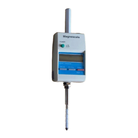
Digital Indicator / Digital Messuhr
U12B / U30B / U60B
Read all the instructions in the manual carefully before use and strictly follow them.
Keep the manual for future references.
Lesen Sie die ganze Anleitung vor dem Betrieb aufmerksam durch und folgen Sie beim Betrieb des Geräts den
Anweisungen. Bewahren Sie diese Bedienungsanleitung zum späteren Nachlesen griffbereit auf.
Instruction Manual / Bedienungsanleitung
Inhaltsverzeichnis

Verwandte Anleitungen für Magnescale U12B


Inhaltszusammenfassung für Magnescale U12B
- Seite 1 Digital Indicator / Digital Messuhr U12B / U30B / U60B Read all the instructions in the manual carefully before use and strictly follow them. Keep the manual for future references. Lesen Sie die ganze Anleitung vor dem Betrieb aufmerksam durch und folgen Sie beim Betrieb des Geräts den Anweisungen.
- Seite 2 Warning : This equipment has been tested and found to comply with the limits for a Class A digital device, pursuant to Part 15 of the FCC Rules. These limits are designed to provide reasonable protection against harmful interference when the equipment is operated in a commercial environment.
-
Seite 3: Safety Precautions
Safety Precautions Magnescale Co., Ltd. products are designed in full consideration of safety. However, improper handling during operation or installation is dangerous and may lead to fire, electric shock or other accidents resulting in serious injury or death. In addition, these actions may also worsen machine performance. - Seite 4 Warning • D not damage, modify, excessively bend, pull on, place heavy objects on or heat the cable, as this may damage the cable and result in fire or electric shock. • Do not disassemble or modify the unit, as this may result in injury or electric shock. These actions may also damage the internal circuitry.
-
Seite 5: Sicherheitsmaßnahmen
Sicherheitsmaßnahmen Bei dem Entwurf von Magnescale Co., Ltd. Produkten wird größter Wert auf die Sicherheit gelegt. Unsachgemäße Handhabung während des Betriebs oder der Installation ist jedoch gefährlich und kann zu Bränden, elektrischen Schlägen oder anderen Unfällen führen, die schwere Verletzungen oder Tod zur Folge haben können. Darüber hinaus kann falsche Anwendung die Leistung der Maschine verschlechtern. - Seite 6 Warnung Das Kabel nicht beschädigen, verändern, übermäßig knicken, daran ziehen, schwere • Objekte darauf stellen oder es erwärmen, da es hierdurch beschädigt und ein Feuer oder ein elektrischer Schlag hervorgerufen werden kann. • Das Gerät nicht zerlegen oder verändern, da dies zu Verbrennungen oder elektrischen Schlägen führen kann.
-
Seite 7: Inhaltsverzeichnis
TABLE OF CONTENTS INHALTSVERZEICHNIS 1. FEATURES ..............1 1. MERKMALE ..............1 2. SPECIFICATIONS ............2 2. TECHNISCHE DATEN ..........2 3. NAME AND FUNCTION OF EACH PART ....3 3. NAME UND FUNKTION DER EINZELNEN TEILE ..3 4. PRECAUTIONS 4. -
Seite 9: Features
1. MERKMALE 1. FEATURES • High accuracy: 0.002 mm/0.0001" (U12B, U30B) • Hohe Genauigkeit: 0,002 mm (U12B, U30B) 0.003 mm/0.00015" (U60B) 0,003 mm (U60B) • Provided with input/output interface (RC-232C) and, when • Die Messuhr ist mit einer V24-Schnittstelle (RS-232C) -
Seite 10: Specifications
2. SPECIFICATIONS 2. TECHNISCHE DATEN Item U12B-F U30B-F U60B-F Gegenstand U12B-F U30B-F U60B-F Measuring range 12 mm/0.5" 30 mm/1.2" 60 mm/2.4" Messbereich 12 mm 30 mm 60 mm Resolution 0.001 mm/0.00005" Auflösung 0,001 mm Accuracy 0.002 mm/0.0001" 0.003 mm Genauigkeit (bei 20 ºC) -
Seite 11: Name And Function Of Each Part
3. NAME AND FUNCTION OF EACH PART/ NAME UND FUNKTION DER EINZELNEN TEILE DC IN DATA OUT Mode indicator Funktionsanzeige MAX MIN P-P POWER Unit indicator Maßeinheit-Anzeige D I G I T A L I N D I C A T O R MODE RECALL RESET... -
Seite 12: Mode Button [Mode]
q Stem: q Schaft: ø8 ø8 mm/0.315" –0.015 –0.0006" –0,015 w Spindle: ø5 mm/0.2" dia w Spindel: ø5 mm e Feeler e Taster Using ø3 carbide ball. M2.5 set screw is used. Verwendung einer ø3-Hartmetallkugel. Gewinde M2,5. Can be interchangeably replaced with other makers’ feelers. Kann durch Taster anderer Hersteller ersetzt werden. - Seite 13 u Memory recall button [RECALL] u (Recall) Speicher-Aufruf-Schalter [RECALL] Used to switch the display between the present value, Umschaltung der Anzeige vom vorliegenden Wert zum max., min., and peak-to-peak value in this sequence. Max.-/Min. Wert und P.-P.-Wert (Spannweite), in dieser Reihenfolge.
- Seite 14 !2 Anschlussöffnung für Luftabheber !2 Air Release mounting hole Hier kann der Luftabhe-ber DZ173 (Sonderzu-behör) The Air Release DZ173 (sold separately) may be mount-ed. angeschlossen werden !3 Hubhebel !3 Lift lever Zur Bewegung der Spindel ohne Benützung des Used to move the spindle without employing the release. Luftabhebers !4 Zoll/mm-Wahlschalter !4 in/mm selector...
-
Seite 15: Precautions
4. PRECAUTIONS 4. ALLGEMEINE HINWEISE FÜR DEN BETRIEB 4-1. General precautions • Before and/or during operations, be sure to check that our 4-1. Allgemeine Hinweise products function normally. • Überprüfen Sie vor oder während des Betriebs, ob die • Provide sufficient safeguard to prevent extensive damages Messuhr normal funktioniert. -
Seite 16: Operating Precautions
4-2. Operating precautions 4-2. Hinweise für den Betrieb • The AC adaptor used to power the Indicator should meet the • Das für die Stromversorgung der Messuhr verwendete requirements of the output rating and the plug polarity to Netzgerät muss den Ausgangs-Nennwerten und der avoid possible malfunction. - Seite 17 • Do not use or leave the Indicator in environments at a • Die Messuhr sollte nicht in einer Umgebung eingesetzt oder temperature of more than 40°C/104°F such as places aufgestellt werden, wo Temperaturen von mehr als 40°C exposed to the direct sun rays, near a heater, etc. auftreten, z.B.
- Seite 18 • Verwenden Sie zum Anbringen und Abnehmen des • When attaching and removing the feeler, use the wrench Masstasters nur den mitgelieferten Schlüssel. Achten Sie provided. Make sure that the torque applied to the spindle darauf, dass das auf die Spindel einwirkende Moment unter is below 0.1 N ·...
-
Seite 19: Operation
5. OPERATION 5. BETRIEB 5-1. Mounting 5-1. Installation To position the Indicator, be sure to Zur Positionierung der Messuhr chuck its stem at its uppermost spannen Sie sie am obersten Teil possible portion. The dedicated des Schaftes ein. Verwenden Sie gauge stand (see page 31) is möglichst den Messtisch DZ521 r e c o m m e n d e d t o m o u n t t h e... -
Seite 20: Setup
5-3. Setup 5-3. Einrichten 1. Anbau des Hubhebels 1. Mounting the Lift Lever Spindle Spindel Entfernen Sie den Taster, und halten Sie Remove feeler and hold the spindle. die Spindel fest. Drücken Sie die Öffnung Press the lift lever’s opening, lower end des Hubhebels, beginnend mit dem first, against the spindle until they firmly unteren Ende, gegen die Spindel, bis... -
Seite 21: Selecting The Counting Direction
5-4. Selecting the Counting Direction 5-4. Wahl der Zählrichtung Stellen Sie mit dem DIR-Schalter das Vorzeichen des an- Use the DIR switch to change the sign of the displayed value gezeigten Werts für die Bewegungsrichtung der Spindel ein. with respect to the spindle’s movement direction. -
Seite 22: Measurement Mode
5-5. Measurement mode 5-5. Messfunktionen 1. Standard mode 1. Normalfunktion Turning on the power sets the Indicator to the Standard Mit Einschalten des Stroms stellt sich die Messuhr auf die mode. Press the RESET button to zeroset the datum point Standardfunktion ein. -
Seite 23: Measuring The Runout
5-7. Measuring the Runout 5-7. Messung der Unrundheit To measure the runout, follow the procedure below. Zur Messung der Unrundheit gehen Sie wie unten beschrieben vor. Indicator Messuhr Runout Object measured Unrundheit Zu messendes Objekt The shaft is rotated. Die Welle wird gedreht... - Seite 24 Procedure Vorgang Operating/Bedienung Display/Anzeige 1. Position the Indicator feeler 1. Den Taster der Messuhr wie gezeigt auf das zu messende with respect to the measured Objekt ansetzen. object as shown. 2. Apply power to the Indicator. 2. Messuhr einschalten. [ MODE ] [ RECALL ] 3.
-
Seite 25: Erneute Messung
• To Renew Measuring • Erneute Messung To check the measurements just obtained or measure Zur Überprüfung der soeben erhaltenen Messung oder zur another object, follow the procedure below. Messung eines anderen Objekts verfahren Sie wie folgt: Procedure Vorgang Operating/Bedienung Display/Anzeige 5. -
Seite 26: Measuring Flatness
5-8. Measuring Flatness 5-8. Messung der Ebenheit To measure the max. height, min. height, and the flatness, Zur Messung der maximalen Höhe, minimalen Höhe und follow the procedure below. Ebenheit gehen Sie wie folgt vor: 20.005 20.000 19.992 19.980 Object measured Zu messendes Objekt 0.000 Measurement table... - Seite 27 Procedure Vorgang Operating/Bedienung Display/Anzeige 1. Turn on the power of the Indi- [ RESET ] 1. Messuhr einschalten, den Taster cator, place the feeler on the auf die Messplatte setzen und datum surface and press the RESET-Schalter drücken. (A) RESET button. (A) 2.
- Seite 28 • To Renew Measuring • • • • • Erneute Messung To check the measurements just obtained or measure Zur Überprüfung der soeben erhaltenen Messung oder zur another object, follow the procedure below. Messung eines anderen Objekts verfahren Sie wie folgt: Procedure Vorgang Operating/Bedienung...
-
Seite 29: Input/Output Interface
6. INPUT/OUTPUT INTERFACE 6. E/A SCHNITTSTELLE Bei Anschluss an die Daten-Ein-/Ausgabebuchse (8-polig) an An RS-232C-compliant interface can be used to perform der Oberseite des Gerätes kann eine RS-232C-kompatible measurement data reading, mode switching, and other Schnittstelle verwendet werden, um Messdatenausgabe, operations when connected from the data input/output connector Modusumschaltung und andere Operationen durchzuführen. -
Seite 30: Specifications Of Rs-232C Interface
6-2. Daten der RS-232C-Schnittstelle 6-2. Specifications of RS-232C Interface Signal : Asynchronous, start-stop, half duplex Signal : Asynchron, Start-Stopp, Halbduplex Flow control : Hardware flow control(RTS, CTS) Ablaufsteuerung : Hardware-Ablaufsteuerung (RTS, CTS) Transfer rate : 2400 bps Übertragungsrate : 2.400 bps Data length : 8 bit Datenlänge... -
Seite 31: Command
6-3. Command 6-3. Befehle Command contents Befehlserläuterung Transmission command/ Contents/Inhalt Return/Rückgabe Übertragungsbefehl □□□□□□□□□□□ Request for present value display Anforderung für Gegenwartswert-Anzeige □□□□□□□□□□□ Request for constant output data Anforderung für Konstant-Ausgabedaten □□□□□□□□□□ Request for maximum value Anforderung für Maximalwert □□□□□□□□□□ Request for minimum value Anforderung für Minimalwert □□□□□□□□□□... - Seite 32 Transmission command/ Contents/Inhalt Return/Rückgabe Übertragungsbefehl □□□□□□□ Set preset value Voreinstellwert einstellen □□□□□□□ Set comparator upper limit value Komparator-Obergrenzwert einstellen □□□□□□□ Set comparator lower limit value Komparator-Untergrenzwert einstellen Display “GO” „GO“ anzeigen Display “:” (Upper limit indicate) „:“ anzeigen (Obergrenze anzeigen) Display “;”...
-
Seite 33: Befehlserläuterung
Command explanation Befehlserläuterung q R (Displayed data readout) q R (Ausgabe der angezeigten Daten) Enables the readout of the current display. Ermöglicht die Ausgabe der gegenwärtigen Anzeige. w F (Constant output data) w F (Konstant-Ausgabedaten) Data is output constantly. In order to stop output data, press D a t e n w e r d e n ko n s t a n t a u s g e g e b e n . - Seite 34 y P (Preset value setting) y P (Einstellung des Voreinstellwerts) Set the preset value. Voreinstellwert einstellen. The preset value loads to present value to the press of the Wenn die Taste RESET/MEM.CL gedrückt oder der Befehl RESET/MEM. CL button or send “C” command to the Indi- „C“...
- Seite 35 Output data format Ausgabedatenformat Rückgabedatenformat Return data format Rückgabedatenformat von R, MA, MI, MP, MN und F Return data format of R, MA, MI, MP, MN and F 1. Byte : R (Im Falle der Sendung des Befehls R) 1st byte : R (In case of sending R command) M (Im Falle der Sendung des Befehls MA, M (In case of sending MA, MI, MP or MN...
- Seite 36 Sending data format Senden des Datenformats Sending data format of P, H and L Senden des Datenformats von P, H und L Input numerical data that is signed 6-digits without decimal Geben Sie numerische Daten in der Form von 6 Ziffern mit point after P, H or L command.
-
Seite 37: Interface Cable
6-4. Interface cable 6-4. Schnittstellenkabel When connecting to a personal computer (called “PC” Wenn Sie das Gerät an einen Personal Computer (im below), use the DZ252 (sold separately) or DZ253A (sold Folgenden „PC“ genannt) anschließen, verwenden Sie das separately) RS-232C cables. RS-232C-Kabel DZ252 (getrennt erhältlich) oder DZ253A (getrennt erhältlich). -
Seite 38: Before You Take It For Failure
7. BEFORE YOU TAKE IT FOR 7. STÖRUNGSÜBERPRÜFUNGEN FAILURE Bei Auftreten von Problemen überprüfen Sie die folgenden Before you conclude the product developed malfunction, check Punkte. the following: 1. Failure to display 1. Keine Anzeige • Is the power switch set to ON? •... -
Seite 39: Accessories (Sold Separately)
8. ACCESSORIES (SOLD 8. SONDERZUBEHÖR SEPARATELY) Luftabheber : DZ173 Schnittstellenkabel : DZ252, DZ253A Air Release : DZ173 Messtisch : DZ521 (U12B, U30B) Interface cable : DZ252, DZ253A ∗ DZ-501 (U60B) Gauge Stand : DZ521 (U12B, U30B) Taster : DZ-5100 ∗... -
Seite 40: Dimensions
(46)/(1.8") 9. DIMENSIONS/ABMESSUNGEN U12B U30B DC IN DATA OUT (46)/(1.8") 60/2.36" DC IN DATA OUT ø12/ø0.47" 60/2.36" POWER POWER D I G I T A L I N D I C A T O R D I G I T A L... - Seite 41 28.5/1.12" ø12.5/ø0.49" U60B 2.28" 2.05" (46)/(1.8") POWER DC IN DATA OUT D I G I T A L I N D I C A T O R MODE RECALL RESET MEM.CL M12×1 16/0.63" ø8 16.4/0.65" –0.015 0" ø0.32" –0.0005" 40/1.57" ø5 ø0.20"...
- Seite 43 The material contained in this manual consists of l'équipement à moins d'une permission écrite de Magnescale Co., Ltd. information that is the property of Magnescale Co., Ltd. and is intended solely for use by the purchasers of the equipment described in this manual.
- Seite 44 Note: This product (or technology) may be restricted by the government in your country. Please make sure that end- use, end user and country of destination of this product do not violate your local government regulation. U12B / U30B / U60B 2015.1...