Herunterladen Inhalt Inhalt Diese Seite drucken
HBM U2A Montageanleitung
Vorschau ausblenden Andere Handbücher für U2A:

Werbung

Verfügbare Sprachen

Verfügbare Sprachen

A1261-1.0 de/en/fr
Montageanleitung
Mounting instructions
Notice de montage
Wägezellen
Load cells
Pesons
U2A

Werbung

Inhaltsverzeichnis
loading

Inhaltszusammenfassung für HBM U2A

  • Seite 1 Montageanleitung Mounting instructions Notice de montage Wägezellen Load cells Pesons A1261-1.0 de/en/fr...
  • Seite 2 Deutsch ..........Seite 3 −...
  • Seite 3: Inhaltsverzeichnis

    Inhalt Seite Sicherheitshinweise ..........1 Bedingungen am Einbauort .
  • Seite 4: Sicherheitshinweise

    Sicherheitshinweise Die Wägezellen können als Maschinenelemente (z.B. bei Behälterverwiegun- gen) eingesetzt werden. Beachten Sie bitte in diesen Fällen, dass die Wäge- zellen zugunsten einer hohen Messempfindlichkeit nicht mit den in Maschi- nenkonstruktionen üblichen Sicherheitsfaktoren konstruiert sind. Wo bei Bruch Menschen und Sachen zu Schaden kommen können, müssen vom Anwender entsprechend den einschlägigen Unfallverhütungsvorschriften Sicherheits- maßnahmen (wie z.B.
  • Seite 5 Bestimmungsgemäßer Gebrauch Die Wägezellen der Typen U2A sind für wägetechnische Anwendungen konzi- piert. Jeder darüber hinausgehende Gebrauch gilt als nicht bestimmungsge- mäß. Zur Gewährleistung eines sicheren Betriebes dürfen die Wägezellen nur nach den Angaben in der Montageanleitung verwendet werden. Bei der Verwen- dung sind zusätzlich die für den jeweiligen Anwendungsfall erforderlichen...
  • Seite 6 Umgebungsbedingungen Beachten Sie in Ihrem Anwendungsfeld, dass alle Stoffe die (Chlor-) Ionen freisetzen, auch nichtrostende Stähle und deren Schweißnähte angreifen. In diesem Fall sind von der Betreiberseite entsprechende Schutzmaßnahmen vorzusehen. Verbot von eigenmächtigen Umbauten und Veränderungen Die Wägezellen dürfen ohne unsere ausdrückliche Zustimmung weder kon- struktiv noch sicherheitstechnisch verändert werden.
  • Seite 7: Bedingungen Am Einbauort

    Nullpunktveränderung [%/10 mbar] 0,065 0,032 0,016 0,006 0,003 0,006 0,003 0,002 0,001 1.2 Spezielle Hinweise Die Aufnehmer U2A sind vollständig aus nichtrostenden Materialien gefertigt. Die Beständigkeit gegen aggressive Umgebungseinflüsse ist im Einzelfall vom Anwender zu prüfen. Montagehinweise • Den Aufnehmer schonend handhaben.
  • Seite 8: Lasteinleitung

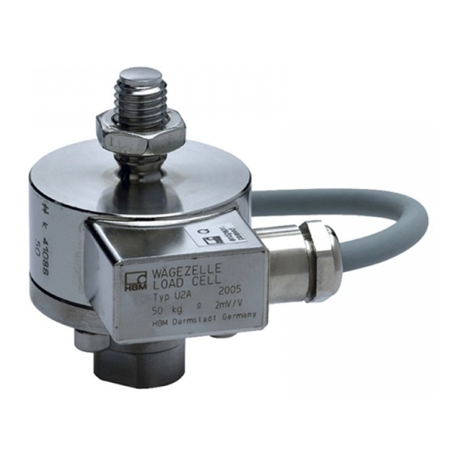
    Lasteinleitung Die Wägezellen der Typenreihe U2A können axiale Lasten sowohl in Zug− als auch in Druckrichtung messen. Zur Einleitung von Zuglasten (Vorzugsrich- tung) sind ein Gewindebolzen am Gehäusekopf und ein Innengewinde am Adapter vorgesehen. Für einen seitenkraft− und momentfreien Anschluss an die Waagenkonstruk- tion empfiehlt HBM die Verwendung von Gelenkösen.
  • Seite 9: Anschließen

    Elektrische und magnetische Felder verursachen oft die Einkopplung von Störspannungen in den Messkreis. Beachten Sie deshalb folgende Hinweise: • Verwenden Sie nur abgeschirmte und kapazitätsarme Messkabel (HBM-Ka- bel erfüllen diese Bedingungen). • Messkabel nicht parallel zu Starkstrom- oder Steuerleitungen verlegen.
  • Seite 10: Parallelschaltung Mehrerer Aufnehmer

    4.5 Kabelverlängerung Verlängerungskabel müssen abgeschirmt und kapazitätsarm sein. Wir emp- fehlen Ihnen die Verwendung von HBM-Kabeln, die diese Voraussetzungen erfüllen. Bei Kabelverlängerungen ist auf eine einwandfreie Verbindung mit geringsten Übergangswiderständen und gute Isolation zu achten. Bei Anwendung der Sechsleiter-Technik werden die Einflüsse durch Wider- standsänderungen der Verlängerungskabel ausgeglichen.
  • Seite 11: Technische Daten

    Technische Daten Genauigkeitsklasse Teilezahl (n − − 1000 Nennlast (E 100, 200, 500 − 1, 2, 5, 10, 20 1, 2, 5 Mindestteilungswert (v % v. − − 0,0286 Nennkennwert (C mV/V Kennwerttoleranz bei Zug <"0,20 <"0,20 <"0,20 bei Druck <"1,50 <"0,50 <"0,50...
  • Seite 12: Mechanische Werte

    II 3 G EEx nA II T6 (Zone 2) II 3 D IP67 T80 °C (Zone 22 für nichtleitenden Staub) *) mit EG−Baumusterprüfbescheinigung Zubehör, zusätzlich zu beziehen: − Gelenköse U2A, oben, U2A/.../ZGOW − Gelenköse U2A, unten, U2A/.../ZGUW − Erdungskabel EEK...
  • Seite 13: Abmessungen (In Mm)

    Abmessungen (in mm) 6.1 Aufnehmer (Nennlasten 50 kg ... 20 t) Draufsicht Nennlast ØA −0,2 in t 0,05 ... 1 10,6 M20x1,5 13,2 M24x2 M39x2 26,5 24,2 M48x2 bei U2A/1t: 7,4 mm A1261-1.0 de/en/fr...
  • Seite 14: Einbauhilfen

    Material: Vergütungsstahl, verzinkt; Wälzlagerstahl und PTFE/Bronzegewebefolie ∅B ∅K Nennlast Gelenköse Gewicht a.f. in t ZGOW [kg] 0,05...1 U2A/1T/ ZGOW U2A/2T / ZGOW M20x1,5 U2A/5T/ ZGOW M24x2 U2A/10T / ZGOW +0,002 212.5 28 M39x2 -0,014 +0,003 U2A/20T / ZGOW M48x2 -0,018...
  • Seite 15 Material: Vergütungsstahl, verzinkt; Wälzlagerstahl und PTFE/Bronzegewebefolie ∅B Nennlast Gelenköse Gewicht SW W in t ZGUW in kg 0,05...1 U2A/ 1T / ZGUW U2A/ 2T / ZGUW 18 M20x1,5 U2A/5T / ZGUW M24x2 U2A/10T / ZGUW 65,5 +0,002 115 148,5 M39x2...
  • Seite 16 Wägezelle U2A mit montierten Gelenkösen ZGOW, ZGUW Nennlast Mindestein- in [t] schraubtiefe 0,05...0,5 19,2 19,2 31,2 36,6 38,4 A1261-1.0 de/en/fr...
  • Seite 17 U2A, mit ZGOW, ohne Adapter um 45° bzw. 22,5° Basisplatte, versetzt gezeichnet kundenseitig *Empfohlenes Maß, unter Beachtung der Mindesteinschraubtiefe ∅G ∅S Nennlast in t [NVm] 0,05...0,5 4xM5 84...86,4 4xM5 86,4 4xM10 20,5 131,6 4xM12 158,2 8xM12 8xM16 270,2 )Empfohlene Werte bei trockenem Gewinde und Benutzung eines Drehmomentschlüssels...
  • Seite 18 A1261-1.0 de/en/fr...
  • Seite 19 Contents Page Safety instructions ..........1 Conditions at the site of installation .
  • Seite 20: Safety Instructions

    Safety instructions The load cells can be used as machine components (e.g. with container weig- hing). Please note in these cases that, in order to provide a high sensitivity, the transducer is not designed with a safety factor which is normally applied in machine design.
  • Seite 21 General dangers due to non-observance of the safety instructions The U2A load cells correspond to the state of the art and are fail-safe. The load cells can give rise to residual dangers if they are inappropriately installed and operated by untrained personnel.
  • Seite 22 Residual dangers The scope of supply and performance of the load cells covers only a small area of weighing technology. In addition, equipment planners, installers and operators should plan, implement and respond to the safety engineering considerations of weighing technology in such a way as to minimise residual dangers.
  • Seite 23: Conditions At The Site Of Installation

    Change of zero point [%/10 mbar] 0.065 0.032 0.016 0.006 0.003 0.006 0.003 0.002 0.001 1.2 Special information The U2A transducers are produced entirely from non-rusting materials. The user must test for resistance to aggressive environmental conditions in each individual case. Mounting instructions •...
  • Seite 24: Load Introduction

    Load introduction The transducers of the series U2A measure tension as well as compression loads in the axial direction. A threaded bolt on top of the housing and an internal thread on the adapter are provided for the application of tensile loads (preferred direction).
  • Seite 25: Connection

    Please note the following hints: • Use only screened, low capacitance measuring cable (cable from HBM full- fills these requirements). • Do not lay the measuring cable parallel to power and control lines. If this is not possible (e.g.
  • Seite 26: Parallel Connection Of More Than One Transducer

    4.5 Cable extension Extension cables must be screened and of the low capacitance type. We re- commend the use of HBM cables which fulfil these requirements. For cable extensions, care must be taken to ensure a satisfactory connection with the lowest possible transfer resistance and goog insulation.
  • Seite 27: Specifications

    Specifications Type Accuracy class Max. numbers of load cell verification intervals (n − − 1000 Max. capacity (E 100, 200, 500 − 1, 2, 5, 10, 20 1, 2, 5 Minimum load cell verification interval % of − − 0.0286 Sensitivity (C mV/V Tolerance on sensitivity...
  • Seite 28: Mechanical Data

    II 3 G EEx nA II T6 (Zone 2) II 3 D IP67 T80 °C (Zone 22 for non-conductive dust) *) with EC-type examination certificate Accessories, to be ordered separately: − Knuckle eye U2A, above, U2A/.../ZGOW − Knuckle eye U2A, below, U2A/.../ZGUW − EEK Grounding cable A1261−1.0 de/en/fr...
  • Seite 29: Dimensions (In Mm; 1 Mm = 0.03937 Inches)

    Dimensions (in mm; 1 mm = 0.03937 inches) 6.1 Transducer (Max. capacities 50 kg ... 20 t) View from above Max. capa- ØA −0,2 city in t 0.05 ... 1 10.6 M20x1.5 13.2 M24x2 M39x2 26.5 24.2 M48x2 with U2A/1t: 7.4 mm A1261−1.0 de/en/fr...
  • Seite 30: Mounting Accessories

    Material: tempering steel, galvanized; rolled steel and PTFE/bronze fabric foil ∅B ∅K Max. Knuckle eye Weight a.f. capacity ZGOW [kg] in t 0.05...1 U2A/1T/ ZGOW U2A/2T / ZGOW M20x1.5 U2A/5T/ ZGOW M24x2 U2A/10T / ZGOW +0.002 212.5 28 M39x2 -0.014 U2A/20T / ZGOW +0.003 M48x2 -0.018...
  • Seite 31 Material: tempering steel, galvanized; rolled steel and PTFE/bronze fabric foil ∅B Max. Knuckle eye Weight a.f. capacity ZGUW in kg in t 0.05...1 U2A/ 1T / ZGUW U2A/ 2T / ZGUW 18 M20x1,5 U2A/5T / ZGUW M24x2 U2A/10T / ZGUW 65.5 50 +0.002 115 148.5 M39x2 -0.014 U2A/20T / ZGUW +0.003...
  • Seite 32 Load cell U2A with mounted knuckle eyes ZGOW, ZGUW Max. Min. depth capacity for screwing in [t] 0.05...0.5 19.2 19.2 31.2 36.6 38.4 A1261−1.0 de/en/fr...
  • Seite 33 U2A, with ZGOW, without adaptor drawing turned by 45° Base plate resp. 22,5° (from customer) * Recommended dimension, taking minimum thread reach into consideration ∅G ∅S Max. capacity [NVm] in t 0.05...0.5 4xM5 84...86.4 4xM5 86.4 4xM10 20.5 131.6 4xM12 158.2...
  • Seite 34 A1261−1.0 de/en/fr...
  • Seite 35 Sommaire Page Consignes de sécurité ......... . 1 Conditions concernant le lieu d’installation .
  • Seite 36: Consignes De Sécurité

    Consignes de sécurité Las capteurs de pesage peuvent être mis en œuvre en tant qu’éléments de machine (pour la pesée en ligne de conteneurs, par exemple). Dans de tels cas, tenir compte du fait que, afin de disposer d’une plus grande précision de mesure, le peson ne présent pas les mêmes facteurs de sécurité...
  • Seite 37 Utilisation conforme Les pesons de la série U2A... sont développés spécialment pour les applica- tions de pesage. Toute utilisation divergente est considérée comme non con- forme. Pour garantir un fonctionnement en toute sécurité de ce capteur, celui-ci doit être utilisé conformément aux instructions de la notice de montage. De plus, il convient de respecter les règlements et consignes de sécurité...
  • Seite 38 Conditions de l’ambiance N’oubliez pas que, dans votre champ d’application, toutes les matières qui li- bèrent des ions (chlore) attaquent également les aciers inoxydables et leurs cordons de soudure. D’où la nécessité pour l’exploitant de prévoir des mesu- res de protection correspondantes. Interdiction de toutes transformations et modifications sans autorisation Il est interdit de modifier la conception ou la sécurité...
  • Seite 39: Conditions Concernant Le Lieu D'installation

    [%/10 mbar] 0,065 0,032 0,016 0,006 0,003 0,006 0,003 0,002 0,001 1.2 Remarques particulières Les capteurs U2A sont entièrement constitués de matériaux inoxydables. La résistance aux influences agressives de l’environnement doit être contrôlée au cas par cas par l’utilisateur.
  • Seite 40: Application De Charge

    Application de charge Les pesons de la série U2A peuvent mesurer des charges axiales aussi bien dans la direction de traction que dans la direction de pression. Pour appliquer des charges en traction (direction privilégiée), un boulon fileté est prévu à la tête du boîtier et l’adaptateur comporte un taraudage.
  • Seite 41: Raccordement

    C’est la raison pour laquelle : • Vous devez utiliser uniquement des câbles de mesure blindés de faible ca- pacité (les câbles HBM satisfont à ces conditions) • Vous ne devez pas poser les câbles de mesure en parallèle avec des câ- bles de commande et d’énergie.
  • Seite 42: Branchement En Parallèle De Plusieurs Capteurs

    4.5 Rallonge de câbles Les câbles prolongateurs (rallonges) doivent être blindés et de faible capacité. Nous recommandons l’utilisation des câbles HBM qui satisfont à ces condi- tions requises. Pour les prolongations de câble, il faut veiller à une parfaite connexion avec des résistances de transition minimes et à une bonne isola- tion.
  • Seite 43: Specifications

    Specifications Type Classe de précision Nombre d’échelons (n − − 1000 Charge nominale (E 100, 200, 500 − 1, 2, 5, 10, 20 1, 2, 5 Valeur min. d’un échelon (v % de − − 0,0286 Valeur caractéristique nominale (C mV/V Tolérance de la valeur caractéristique <"0,20...
  • Seite 44: Caractéristiques Mécaniques

    II 3 D IP67 T80 °C (Zone 22 pour poussière non conductrice) avec certificat d’examen CE de type Accessoires (non compris dans la livraison) : − Anneaux à rotule U2A, pour le haut, U2A/.../ZGOW − Anneaux à rotule U2A, pour le bas, U2A/.../ZGUW...
  • Seite 45: Dimensions (En Mm)

    Dimensions (en mm) 6.1 Capteur (Charges nominales 50 kg...50 t) Sur plats vue de dessus Charge ØA −0,2 nomi- plats nale en t 0,05 ... 1 10,6 M20x1,5 13,2 M24x2 M39x2 26,5 24,2 M48x2 avec U2A/1t: 7,4 mm A1261-1.0 de/en/fr...
  • Seite 46: Pièces Pour Le Montage

    Matériau: acier trempé, galvanisé; acier laminé et PTFE/feuillard de bronze ∅B ∅K Charge Anneaux à ro- Poids s.p. W tule ZGOW [kg] nomi- nale en 0,05...1 U2A/1T/ ZGOW U2A/2T / ZGOW M20x1,5 U2A/5T/ ZGOW M24x2 U2A/10T / ZGOW +0,002 212.5 28 M39x2 -0,014 +0,003 U2A/20T / ZGOW M48x2 -0,018...
  • Seite 47 Matériau: acier trempé, galvanisé; acier laminé et PTFE/feuillard de bronze ∅B Charge Anneaux à ro- Poids s.p. tule ZGOW in kg nomi- nale en 0,05...1 U2A/ 1T / ZGUW U2A/ 2T / ZGUW 18 M20x1,5 U2A/5T / ZGUW M24x2 U2A/10T / ZGUW 65,5 50 +0,002 115 148,5 M39x2 -0,014...
  • Seite 48 Peson U2A avec oeillets articulés montés ZGOW, ZGUW Charge Profondeur filetée mini- nominale male en t 0,05...0,5 19,2 19,2 31,2 36,6 38,4 A1261-1.0 de/en/fr...
  • Seite 49 U2A, avec ZGOW, sans adaptateur dessin décalé de 45° plaque de base, ou de 22,5° incombe au client *cote recommandée en veillant à la profondeur filetée minimum ∅G ∅S Charge nomi- [NVm] nale en t 0,05...0,5 4xM5 84...86,4 4xM5 86,4...
  • Seite 50 A1261-1.0 de/en/fr...
  • Seite 52 Hottinger Baldwin Messtechnik GmbH Postfach 10 01 51, D-64201 Darmstadt Im Tiefen See 45, D-64293 Darmstadt Tel.: 061 51/ 8 03-0; Fax: 061 51/ 8039100 A1261-1.0 de/en/fr E−mail: support@hbm.com www.hbm.com...

Inhaltsverzeichnis