elv FHT8-Set Bedienungsanleitung
Funk-heizkörperthermostat

Verwandte Anleitungen für elv FHT8-Set


Inhaltszusammenfassung für elv FHT8-Set
- Seite 1 Bedienungsanleitung User manual FHT8-Set Funk-Heizkörperthermostat Komplettset (S. 1) Heating control set (P. 38) ELV Elektronik AG • PF 1000 • D-26787 Leer Telefon 0491/6008-88 • Telefax 0491/6008-244...
- Seite 2 1. Ausgabe Deutsch Januar 2010 Dokumentation © 2010 ELV Ltd. Hongkong Alle Rechte vorbehalten. Ohne schriftliche Zustimmung des Herausgebers darf dieses Handbuch auch nicht auszugs weise in irgendeiner Form reproduziert werden oder unter Verwendung elektronischer, mechanischer oder chemischer Verfahren vervielfältigt oder verarbeitet werden.
-
Seite 3: Inhaltsverzeichnis
Inhalt 1. Beschreibung des Systems ..........4 1.1 Allgemeine Informationen/Verwendungszweck..4 1.2 Funktionsweise ............5 1.3 Sicherheitscode ............5 1.4 Technische Hinweise ..........6 1.5 Lieferumfang ............. 7 2. Sicherheitshinweise ............7 3. Installation des Systems..........7 3.1 Anbringen der Regeleinheit FHT 8R ......7 3.2 Anbringen des Ventilantriebes FHT 8V .... -
Seite 4: Beschreibung Des Systems
1. Beschreibung des Systems 1.1 Allgemeine Informationen/Verwendungszweck Das FunkHeizkörperthermostatSystem dient zur Tempera turregelung in Einzelräumen, in denen die Regulierung der über Heizkörper abgegebenen Wärme durch die Drosselung des Heizwasserflusses erfolgt. Das System ist nur bestimmungsgemäß einzuset zen. Eine anderweitige Verwendung, z. B an Kühl anlagen, Fußbodenheizungen etc. -
Seite 5: Funktionsweise
1.2 Funktionsweise In der Regeleinheit FHT 8R wird die Raumtemperatur gemes sen und mit der durch das Zeitprogramm bzw. der von Hand vorgegebenen SollTemperatur verglichen. Aus der Differenz errechnet der Regelalgorithmus, wie das Ventil verfahren wer den muss, um die gewünschte Temperatur zu erreichen. In einem Zeitraster von ca. -
Seite 6: Technische Hinweise
1.4 Technische Hinweise • Verwenden Sie ausschließlich Alkaline-Batterien. Akkus und andere Batterien eignen sich aufgrund der geringeren Spannung bzw. starken Selbstentladung nicht und können Funktionsstörungen verursachen. • Die Freifeld-Reichweite des verwendeten Funksystems liegt bei 100 m. Dies ist für die innerhalb eines Raumes zu über brückende, wesentlich geringere Distanz auch unter den systembedingt ungünstigen Umgebungsbedingungen (Ab... -
Seite 7: Lieferumfang
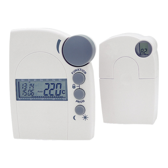
Änderungen der Raumtemperatur durch das Öffnen einer Tür, zu verhindern wird der Messwert über mehrere Mes sungen gemittelt. 1.5 Lieferumfang 1 x Regeleinheit FHT 8R 1 x Wandhalter für die Regeleinheit mit Befestigungsmaterial 1 x Ventilantrieb FHT 8V 1 x Satz Adapterringe für DanfossVentile (3 Stück) 1 x Bedienungsanleitung 4 x MignonBatterie 1 x Kurzanleitung... -
Seite 8: Einlegen Der Batterien In Die Regeleinheit
• in Augenhöhe liegen • nicht an einer schlecht isolierten Außenwand sein • keiner direkten Sonnenbestrahlung unterliegen • nicht auf großen Metallgegenständen sein • keinen Störeinflüssen von Wärmequellen wie Fernseher, Lampen, Kühlschränke etc. ausgesetzt sein 3.1.2 Montage des Wandhalters Zur Montage gehen Sie wie folgt vor: • Nehmen Sie den Wandhalter von der Rückseite der Re geleinheit ab, indem Sie diesen nach unten schieben. • Halten Sie den Wandhalter mit der runden Seite nach oben weisend lotrecht an die Wand. • Markieren Sie durch die beiden Langlöcher die Position der Boh... - Seite 9 • Schließen Sie das Batteriefach. Nach einem kurzen Displaytest sind folgende Einstellungen an der Regeleinheit vorzunehmen: • Einstellung Jahr: Es erscheint folgende Anzeige: M� O � DI� M� I � DO� F� R � S� A � S� O � P� r � o � g � 1� 2 � 0� 6�...
- Seite 10 MI DO FR SA • Stellen Sie mit dem Stellrad die Stunden ein und • bestätigen Sie mit der Taste „PROG”. • Es erscheint folgende Anzeige: MI DO FR SA • Stellen Sie mit dem Stellrad die Minuten ein. • Bestätigen Sie mit der Taste „PROG”. • Anschließend zeigt das Dis play „Sync” und „120” an. Jetzt zählt die Regeleinheit im 1SekundenTakt herunter und befindet sich nach Ablauf von 120 Sekunden im normalen Be...
-
Seite 11: Anbringen Des Ventilantriebes Fht 8V
3.2 Anbringen des Ventilantriebes FHT 8V 3.2.1 Entfernen des alten Thermostaten • Entfernen Sie den alten, me chanischen Thermostaten. Bei fest sitzenden Verschrau bungen hierfür ggf. eine Was serpumpenzange verwenden. 3.2.2 Einlegen der Batterien in den Ventilantrieb • Entfernen Sie den Batterie fachdeckel des Ventilantriebes durch Schieben nach unten. -
Seite 12: Montage Des Ventilantriebs Am Heizkörper
te 2teilige Sicherheitscode des Ventilantriebes). • Im Anschluss erfolgt ein Signalton sowie die Anzeige „A1”. • Der Ventilantrieb fährt jetzt den Steuerstift ganz zurück, um die Montage zu erleichtern. • Anschließend erscheint in der Anzeige „A2”. 3.2.3 Montage des Ventil- antriebs am Heizkörper • Schrauben Sie den Ventil- antrieb durch Drehen der Über wurfmutter von Hand fest auf das Ventil (1). -
Seite 13: Programmieren Des Systems
Sollen weitere Ventilantriebe montiert werden, gehen sie zur Montage wie zuvor beschrieben vor. Anschlie ßend muss an der Regeleinheit, wie unter Punkt 4.9.5 „no H” beschrieben, die Anzahl der Heizkörper/Venti lantriebe eingestellt und der Sicherheitscode übertra gen werden. Die Adapter für die Ventile Typ RAVL RAV und RA sind nach dem Aufrasten auf den Ventilkörper... -
Seite 14: Einstellen Der Komforttemperatur Und Der Absenktemperatur
• Entkalkungsfahrt: Samstag, 11:00 Uhr Alle genannten Einstellungen lassen sich verändern und so an die individuellen Bedürfnisse anpassen. Eine geöffnete Programmier oder Sonderfunktion wird automatisch nach 30 Sekunden Inaktivität wieder ge schlossen. 4.1 Einstellen der Komforttemperatur und der Absenktemperatur Ist der AutomatikModus aktiv, d. h. es erfolgt ein selbsttä tiger Wechsel zwischen Absenk... -
Seite 15: Das Wochenprofil Gestalten
• Es erscheint die Anzeige: MI DO FR SA SO • Stellen Sie die gewünschte Absenktemperatur mit dem Stellrad ein. • Betätigen Sie die Taste „ ” kurz, wonach der Regler in den normalen Betriebsmodus zurückkehrt. 4.2 Das Wochenprofil gestalten Die Zeitsteuerung für den automatischen Wechsel zwischen Komfort... - Seite 16 a) die Werktage (MoFr) b) das Wochenende (SaSo) c) und alle Tage (MoSo) erfolgen • Nach Auswahl der/des Wochentage/s bestätigen Sie die sen durch Drücken der „PROG”Taste. • Es erscheint die Anzeige für die erste Komforttemperatur- Zeit: MI DO FR SA SO Prog • Wählen Sie mit dem Stellrad den Zeitpunkt, ab dem auf die Komforttemperatur geregelt werden soll. • Bestätigen Sie diesen durch Betätigen der „PROG”-Taste • Es erscheint in der Anzeige der erste Absenk-Zeitpunkt: MI DO FR SA SO Prog • Wählen Sie mit dem Stellrad den Zeitpunkt, ab dem auf...
-
Seite 17: Betriebsarten
MI DO FR SA SO Prog • Alle Einstellungen sind jeweils durch Betätigen der „PROG”Taste zu bestätigen. Auf das Programmieren der 2. AbsenktemperaturZeit folgt wieder der normale Be triebsmodus. Die Skala am unteren Displayrand folgt den aktuellen Än derungen, sodass die Auswirkungen auf das Tagesprofil direkt zu erkennen sind. -
Seite 18: Urlaubs-/Partyfunktion In Dieser Betriebsart (Koffersymbol Im Display) Verbleibt
„ ”zeigen an, ob die Absenktemperatur oder die Kom forttemperatur aktiv ist. Soll die Temperatur vorübergehend verändert werden, so kann dies einfach über das Stellrad erfolgen. Beim nächsten regulären Temperaturwechsel im Zeitprogramm kehrt der Thermostat dann selbsttätig zum zeitgesteuerten Programm zurück. 4.3.2 Manueller Betrieb Im manuellen Betrieb (Anzeige „Manu”) verbleibt der Reg... -
Seite 19: Tastensperre
4.4 Tastensperre Um das Gerät vor einem unbeabsichtigten Verstellen z. B. durch Kinder zu schützen, ist eine Sperrfunktion für die Ta sten und das Stellrad integriert. • Um die Sperre zu aktivieren, sind die Tasten „FUNKTION” und „PROG” gleichzeitig zu betätigen. • In der Anzeige erscheint „LOC” und alle Bedienfunktionen sind gesperrt. Um die Sperrfunktion aufzuheben, sind die Tasten „FUNKTI ON”... -
Seite 20: Schließen Des Ventils
Um die Heizpause zu aktivieren, • Wechseln Sie durch Betätigen der Taste „FUNKTION” in die Betriebsart „Manu”. Drehen Sie das Stellrad so lange rechts herum, bis „On” in der Anzeige erscheint. MI DO FR SA SO Manu 4.7 Schließen des Ventils Diese Betriebsart ist zu wählen, wenn der Raum gar nicht geheizt werden soll. -
Seite 21: Notbetrieb Des Ventilantriebes
4.8 Notbetrieb des Ventilantriebes Sollte es aufgrund eines nicht be hebbaren Fehlers (z.B. weil die Bat terien leer sind und kurzfristig kein Ersatz zur Verfügung steht) nötig sein, das Ventil von Hand zu verstel len, ist dies wie folgt möglich: • Entfernen Sie beide Batterien. • Entnehmen Sie den Verstellstift durch Drücken auf die mit (1) ge... - Seite 22 An A Festlegen der Anzahl der Ventile, die der Regler steuert bzw. System erweitern (6) SYnC Aufsynchronisieren der Ventilantriebe tESt Testfunktion für die Funkübertragung StEL Anzeigen der Ventilposition tAn Umschalten zwischen Soll bzw. IstTemperaturanzeige (10) OFFS Offseteinstellung (nur bei mehreren Ventilantrieben) 4.9.1 Sonderfunktion „CALC”/ Festlegen des Entkalkungszeitpunktes Einmal wöchentlich wird das Ventil vollständig geöffnet und geschlossen.
-
Seite 23: Einstellen Von Datum Und Uhrzeit
MI DO FR SA SO • Stellen Sie mit dem Stellrad die Uhrzeit ein. • Bestätigen Sie diese mit der „PROG”-Taste. 4.9.2 Auswählen der Einheit für die Temperaturanzeige Hier kann mit dem Stellrad ausgewählt werden, ob die An zeige der Solltemperatur in Grad Celsius oder Grad Fahren heit erfolgen soll. • Betätigen Sie die Taste „PROG” so lange, bis „Sond” in der Anzeige erscheint. • Wählen Sie mit dem Stellrad die Sonderfunktion „°C°F” aus. • Bestätigen Sie diese mit der „PROG”-Taste. • Wählen Sie mit dem Stellrad „°C” oder „°F” aus. - Seite 24 Sicherheitscode. Jeder Teil umfasst 100 verschiedene Ein stellmöglichkeiten, sodass insgesamt 10000 verschiedene Sicherheitscodes zur Verfügung stehen. Damit die Regel einheit FHT 8R und der/die Ventilantriebe FHT 8V miteinan der kommunizieren können, muss bei allen Geräten eines Raumes der selbe Sicherheitscode eingestellt sein. Werks seitig wurde diesem Set bereits ein (zufälliger) Sicherheits...
- Seite 25 • Stellen Sie mit dem Stellrad den zweiten Teil des Codes ein (000 bis 099). • Bestätigen Sie mit der „PROG”-Taste. • Es erscheint folgende Anzeige: MI DO FR SA SO Es folgt das Synchronisieren des (ersten) Ventilantriebes („001” im Display) auf den neuen Gerätecode. • Entfernen Sie den Batteriefachdeckel des (ersten) Venti lantriebes durch Schieben nach unten. • Betätigen Sie die Taste des Ventilantriebs für ca. 3 Sekun den bis 3 Signaltöne erklingen. Der Ventilantrieb ist jetzt empfangsbereit und das Display zeigt „AC”.
- Seite 26 Wenn die Regeleinheit mehrere Ventilantriebe steuert, sich also mehrere Heizkörper in dem Raum befinden, so sollten Sie notieren, welcher Ventilantrieb zu wel chem Heizkörper gehört, d. h. welche Nummer er hat. Schlägt das Codieren bei einem Ventilantrieb fehl, so kann diesem Ventilantrieb der Code nachträglich neu übermittelt werden: • Gehen Sie wie zuvor beschrieben vor und übersprin gen Sie die bereits codierten Ventilantriebe mit der PROGTaste.
- Seite 27 (1 bis 8) aus. • Bestätigen Sie mit der „PROG”-Taste. • Es erscheint folgende Anzeige: M� O � DI� M� I � DO� F� R � S� A � S� O � 6� 1� 2 � 0� 1� 8 � 2� 4 � Es folgt das Synchronisieren des (ersten) Ventilantriebes („001”...
- Seite 28 in den normalen Betriebsmodus. Ventilantriebe, die bereits auf einen Sicherheitscode synchronisiert sind, können Sie überspringen. Betäti gen sie dazu die „PROG”Taste an der Regeleinheit ggf. mehrmals. 4.9.6 SynC Wird dieser Menüpunkt ausgewählt, so beginnt der Regler für ca. 2 Minuten allen Ventilantrieben zu signalisieren, dass sie sich neu aufsynchronisieren sollen.
- Seite 29 Timer in der linken oberen Anzeige zählt bis zum nächsten Sendezeitpunkt herunter. • Betätigen Sie die Taste „PROG” so lange, bis „Sond” in der Anzeige erscheint. • Wählen Sie mit dem Stellrad die Sonderfunktion „tESt” aus. • Bestätigen Sie diese mit der „PROG”-Taste. • Wählen Sie mit dem Stellrad den/ die zu testenden Ventil- antriebe aus. • Eine Betätigung der „PROG”-Taste beendet die Test- Funktion. 4.9.8 StEL Nach Anwahl dieses Menüpunktes kann im Display abge lesen werden, um wie viel Prozent das Ventil etwa geöff...
- Seite 30 es sich bei der angezeigten Temperatur um die Solltempe ratur handelt. Wird der eingestellte Wert einige Sekunden lang nicht mehr geändert, so kehrt der Regler automatisch zur Anzeige der Isttemperatur zurück. Um die Anzeige der Isttemperatur zu aktivieren bzw. zu de aktivieren gehen Sie wie folgt vor: • Betätigen Sie die Taste „PROG“ so lange, bis „Sond“ in der Anzeige erscheint.
-
Seite 31: Batteriewechsel
bis die Verteilung der Heizleistung optimal erscheint. Der im Display angezeigt Prozentwert wird durch die Offseteinstellung nicht verändert. Der Offsetwert hat lediglich einen Einfluss auf die Steilheit der Ventilkenn linie. Bei einem vom Regler vorgegebenen Stellwert von 10 % z. B. ist ein Ventil mit positivem Offset weiter geöffnet als ein Ventil mit negativem Offset, beide zei... -
Seite 32: Ventilantrieb
• Da die Synchronität zwischen Regeleinheit und Ventilan trieb nicht mehr gegeben ist, führt die Regeleinheit ein ca. 2 Minuten dauerndes automatisches Aufsynchronisieren durch (SYnc Auto). Danach kehrt das Gerät in den norma len Betriebsmodus zurück. 5.2 Ventilantrieb Sind die Batterien des Ventilantriebes erschöpft, gibt dieser eine Stunde lang etwa alle 2 Minuten eine Tonfolge ab und das LowBatSymbol erscheint im Display. - Seite 33 • Anschließend blinkt das Antennensymbol im Display und das Display zeigt „0%” an. • Das erste empfangene Funksignal wir mit einem Signalton bestätigt und das Antennensymbol ist dauerhaft aktiv. • Setzen Sie den Batteriefachdeckel auf.
-
Seite 34: Problembehebung
6. Problembehebung 6.1 Fehlermeldungen Fehlermeldung mögliche Ursache Behebung Dauerhafter Das Ventil ist zu • Ventilantrieb Signalton und schwer gängig bzw. demontieren „F1” im Display der Ventilantrieb ist • Gängigkeit des blockiert Ventils von Hand überprüfen • Ventilantrieb erneut montieren • ggf. einen Heizungs- fachmann zu Rate ziehen Dauerhafter • Ventilantrieb nicht • Ventilantrieb neu Signalton und montiert montieren „F2” im Display • Stellbereich zu groß • Ventil ist nicht geeignet Dauerhafter... -
Seite 35: Störungen Der Funkübertragung
Low-Bat-Symbol • Die Batterien des • Batterien erneuern im Display, der Ventilantriebes sind Ventilantrieb gibt fast leer eine Stunde lang alle 2 Minuten eine Tonfolge aus 6.2 Störungen der Funkübertragung Eine Verminderung der Reichweite der Funkübertragung kann folgende Ursachen haben: • Hochfrequenzstörungen aller Art • Der Abstand der Regeleinheit oder des Ventilantriebes zu leitenden Flächen oder Gegenständen (auch zum mensch lichen Körper oder dem Erdboden) beeinflusst die Strah... -
Seite 36: Hinweise Zum Funkbetrieb
Empfangseigenschaften der Empfänger spielen Umweltein flüsse wie Luftfeuchtigkeit neben baulichen Gegebenheiten eine wichtige Rolle. Hiermit erklärt die die ELV Elektronik AG,, dass sich dieses Gerät in Übereinstimmung mit den grundlegenden Anforde rungen und den anderen relevanten Vorschriften der Richtlinie 1999/5/EG befindet. Die vollständige Konformitätserklärung finden Sie unter www.elv.de. -
Seite 37: Technische Eigenschaften
9. Technische Eigenschaften FHT8R-3 Typische Freifeldreichweite ........bis 100 m Maximale Anzahl Stellantriebe pro Regler......8 Funkfrequenz ............ 868,35 MHz Stromversorgung ........2 LR6 (Mignon/AA) Batterielebensdauer .......... ca. 2 Jahre Temperaturbereich........ 6 °C bis 30 °C Max. Anzahl der Schaltzeiten 4 pro Tag bzw. 28 pro Woche FHT8V-2 Reichweite (Freifeld)..........