Werbung
Verfügbare Sprachen
Verfügbare Sprachen
Quicklinks
Istruzioni per installazione, uso e manutenzione
Installations-, Bedienungs- und Wartungsanleitung
Instructions pour l'installation, l'utilisation et l'entretien
Installation, use and maintenance instructions
Handleiding voor installatie, gebruik en onderhoud
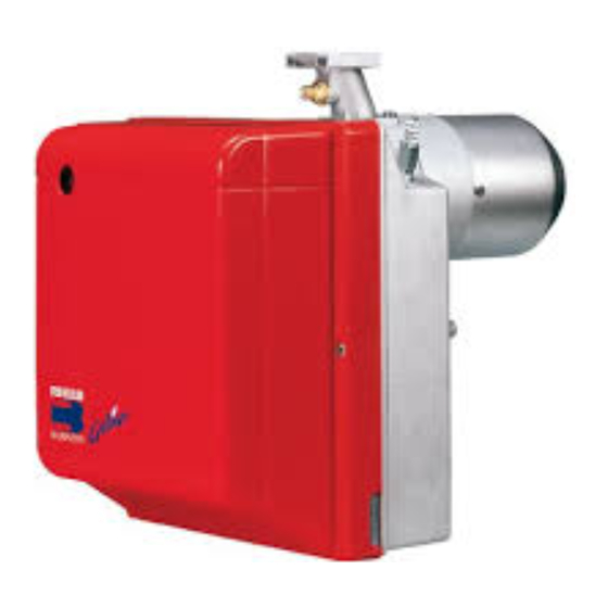
Bruciatori di gasolio
I
Öl-Gebläsebrenner
D
Brûleurs fioul domestique
F
Light oil burners
GB
Stookoliebranders
NL
Funzionamento bistadio
Zweistufiger Betrieb
Fonctionnement à 2 allures
Two stage operation
Tweetrapsbrander
CODICE - CODE
3736650
All manuals and user guides at all-guides.com
MODELLO - MODEL - MODELE
MODEL
RG1RKD
TIPO - TYPE
366 T1
2902305 (8) - 05/2016
Werbung

Verwandte Anleitungen für Riello 3736650


Inhaltszusammenfassung für Riello 3736650
- Seite 1 Öl-Gebläsebrenner Brûleurs fioul domestique Light oil burners Stookoliebranders Funzionamento bistadio Zweistufiger Betrieb Fonctionnement à 2 allures Two stage operation Tweetrapsbrander MODELLO - MODEL - MODELE CODICE - CODE TIPO - TYPE MODEL 3736650 RG1RKD 366 T1 2902305 (8) - 05/2016...
- Seite 2 All manuals and user guides at all-guides.com...
- Seite 3 All manuals and user guides at all-guides.com INDICE DESCRIZIONE DEL BRUCIATORE ..FUNZIONAMENTO ....1.1 Materiale a corredo ....4.1 Regolazione della combustione.
- Seite 4 All manuals and user guides at all-guides.com DATI TECNICI 2.1 DATI TECNICI TIPO 366 T1 ÷ ÷ Portata – Potenza termica 1,2 / 1,45 5 kg/h – 14 / 17 60 kW ÷ Combustibile Gasolio, viscosità 4 6 mm /s a 20°C ±...
- Seite 5 All manuals and user guides at all-guides.com INSTALLAZIONE 3.1 FISSAGGIO ALLA CALDAIA L’INSTALLAZIONE DEL BRUCIATORE DEVE ESSERE EFFETTUATA IN CONFORMITÀ ALLE LEGGI E NORMATIVE LOCALI. Inserire sulla flangia (1) la vite e i due dadi, (vedi fig. 3). Allargare, se necessario, i fori dello schermo isolante (5), (vedi fig. 4). Fissare alla portina della caldaia (4) la flangia (1) mediante le viti (2) e (se necessario) i dadi (3) interponendo lo schermo isolante (5), (vedi fig.
- Seite 6 All manuals and user guides at all-guides.com 3.3 IMPIANTI IDRAULICI ATTENZIONE Accertarsi, prima di mettere in funzione il bruciatore, che il tubo di ritorno del combustibile non abbia occlusioni. Una eccessiva contropressione provocherebbe la rottura dell’organo di tenuta della pompa. La pompa è...
- Seite 7 All manuals and user guides at all-guides.com 3.4 COLLEGAMENTI ELETTRICI NOTE: ATTENZIONE – Sezione dei conduttori: min. 1 mm NON SCAMBIARE IL (Salvo diverse indicazioni di norme e leggi locali). NEUTRO CON LA FASE – I collegamenti elettrici eseguiti dall’installatore devono rispettare le norme vigenti nel paese.
- Seite 8 All manuals and user guides at all-guides.com FUNZIONAMENTO 4.1 REGOLAZIONE DELLA COMBUSTIONE In conformità con la Direttiva Rendimento 92/42/CEE, l’applicazione del bruciatore alla caldaia, la regola- zione e il collaudo, devono essere eseguiti nell’osservanza del manuale d’istruzione della caldaia stessa, compreso il controllo della concentrazione di CO e CO nei fumi, della loro temperatura e di quella media dell’acqua della caldaia.
- Seite 9 All manuals and user guides at all-guides.com Fig. 12 – Estrarre il gruppo portaugello (1) dopo aver allentato le viti (2), svitato il dado (3), sfila- to i cavetti (4) dall’apparecchiatura, la foto- resistenza (5) e la presa (6). – Sfilare i cavetti (4) dagli elettrodi, estrarre dal gruppo portaugello (1) il gruppo sup- porto elica (9) dopo aver allentato la vite (3, fig.
- Seite 10 All manuals and user guides at all-guides.com 4.3 PRESSIONE POMPA E PORTATA ARIA REGOLAZIONE 1° STADIO REGOLAZIONE SERRANDA ARIA Allentare il dado (1), agire sulla vite (2) e portare l’indice (3) sulla posizione desiderata. Quindi bloccare il dado (1),(vedi fig. 14). REGOLAZIONE PRESSIONE Viene tarata in fabbrica a 9 bar.
- Seite 11 All manuals and user guides at all-guides.com 4.4 RISCALDAMENTO DEL COMBUSTIBILE Per garantire l’accensione ed il funzionamento regolari anche alle basse temperature, il bruciatore è dotato di un riscaldatore del gasolio nella testa di combustione. Il riscaldatore si inserisce alla chiusura dei termostati. Il consenso all’avviamento del bruciatore avviene mediante un termostato posto sul portaugello una volta raggiunta la temperatura ottimale per l’accensione.
- Seite 12 All manuals and user guides at all-guides.com ANOMALIE / RIMEDI Si elencano alcune cause e i possibili rimedi a una serie di anomalie che potrebbero verificarsi e portare ad un mancato o non regolare funzionamento del bruciatore. Un’anomalia, nel funzionamento nella maggior parte dei casi, porta alla accensione della segnalazione all’in- terno del pulsante di sblocco dell’apparecchiatura di comando e controllo (pos.
- Seite 13 All manuals and user guides at all-guides.com INDEX BESCHREIBUNG DES BRENNERS . . . BETRIEB ......1.1 Mitgeliefertes Zubehör ....4.1 Einstellung der Brennerleistung.
- Seite 14 All manuals and user guides at all-guides.com TECHNISCHE MERKMALE 2.1 TECHNISCHE DATEN 366 T1 ÷ ÷ Durchsatz - Feuerungswärmeleistung 1,2 / 1,45 5 kg/h – 14 / 17 60 kW ÷ Brennstoff Heizöl-EL, Viskosität 4 6 mm /s bei 20°C ±...
- Seite 15 All manuals and user guides at all-guides.com INSTALLATION 3.1 BRENNERMONTAGE Abb. 2 Abb. 4 D5012 Abb. 3 S7189 Die Schraube und die beiden Muttern am Flansch (1) montieren, (siehe Abb. 3). Falls erforderlich, die Bohrungen der Isolierdichtung (5) erweitern, (siehe Abb. 4). Mit den Schrauben (2) und (falls erforderlich) den Muttern (3) den Flansch (1) an der Kesseltür (4) mit Isolierdichtung (5) montieren, (siehe Abb 2).
- Seite 16 All manuals and user guides at all-guides.com 3.3 ÖLVERSORGUNGSANLAGE WICHTIGER HINWEIS: Es muß sichergestellt werden, daß die Ölrücklauf-Leitung ohne Verengung und Verstopfung frei in den Tank zurückgeführt wird. Durch Druckerhöhung von mehr als 0,5 bar im Rücklauf wird die Ölpumpe undicht. Die Pumpe ist werksseitig für den Zweirohr-Betrieb eingerichtet.
- Seite 17 All manuals and user guides at all-guides.com 3.4 ELEKTRISCHES VERDRAHTUNGSSCHEMA ANMERKUNGEN: WICHTIGER HINWEIS – Leiterdurchmesser 1 mm 2 . NULLEITER NICHT MIT DER – Die vom Installateur ausgeführten elektrischen Verbindungen PHASE VERWECHSELN. müssen den Lokalen Bestimmungen entsprechen. 2. Stufe Thermostat zwischen T6 und T8 Klemmen an- schliessen, dabei die Brücke entfernen.
- Seite 18 All manuals and user guides at all-guides.com BETRIEB 4.1 EINSTELLUNG DER BRENNERLEISTUNG In Konformität mit der Wirkungsgradrichtlinie 92/42/EWG müssen die Anbringung des Brenners am Heizkessel, die Einstellung und die Inbetriebnahme unter Beachtung der Betriebsanleitung der Heizkessels ausgeführt werden, einschließlich Kontrolle der Konzentration von CO und CO in den Abgasen, ihrer Temperatur und der mittlenen Kesseltemperatur.
- Seite 19 All manuals and user guides at all-guides.com Abb. 12 – Den Düsenstock (1) heraus- nehmen, nachdem vorher die Schrauben (2) gelockert, die Mutter (3) gelöst, die Zündkabel (4) vom Steuergerät, der Photowiderstand (5) und die Steckdose (6) abgenommen wurden. – Die Zündkabel (4) von den Elektroden abneh- men, den Stauscheibenhalter (9) vom Düsen- stock (1) herausnehmen, nachdem die Schraube (3, Abb.
- Seite 20 All manuals and user guides at all-guides.com 4.3 PUMPENDRUCK UND LUFTDURCHSATZ EINSTELLUNG 1. STUFE LUFTKLAPPENEINSTELLUNG Die Kontermutter (1) lösen und durch Drehen der Schraube (2) den Zeiger (3) auf die gewünschte Stellung einstellen. Dann die Kontermutter (1) wieder festdrehen, (siehe Abb. 14). DRUCKEINSTELLUNG Wird werksseitig auf 9 bar eingestellt.
- Seite 21 All manuals and user guides at all-guides.com 4.4 VORWÄRMUNG DES HEIZÖL–EL Um auch bei niedrigen Heizöl–Temperaturen eine ordnungsgemäße Zündung zu ermöglichen, ist der Brenner mit einer Ölvorwärmung ausgestattet. Ein Thermostat in der Ölvorwärmung gibt den Brenner erst bei einer Heizöltemperatur von 70 °C frei und ein zusätzlich eingebauter PTC–Widerstand sorgt für eine gleichbleibende Öltemperatur.
- Seite 22 All manuals and user guides at all-guides.com STÖRUNGEN / ABHILFE Nachfolgend finden Sie einige denkbare Ursachen und Abhilfemöglichkeiten für Störungen, die den Betrieb des Brenners beeinflussen oder einen nicht ordnungsgemäßen Betrieb des Brenners verursachen könnten. In den meisten Fällen führt eine Störung zum Aufleuchten der Kontrolleuchte in der Entstörtaste des Steu- ergeräts (4, Abb.
- Seite 23 All manuals and user guides at all-guides.com SOMMAIRE DESCRIPTION DU BRULEUR ..FONCTIONNEMENT....1.1 Matériel fourni ....4.1 Réglage de la combustion .
- Seite 24 All manuals and user guides at all-guides.com DONNEES TECHNIQUES 2.1 DONNEES TECHNIQUES TYPE 366 T1 ÷ ÷ Débit - Puissance thermique 1,2 / 1,45 5 kg/h – 14 / 17 60 kW ÷ Combustible Fioul domestique, viscosité 4 6 mm /s à...
- Seite 25 All manuals and user guides at all-guides.com INSTALLATION 3.1 FIXATION A LA CHAUDIERE Fig. 2 Fig. 4 D5012 Fig. 3 S7189 Insérer sur la bride (1) la vis et deux écrous, (voir fig. 3). Elargir, si nécessaire, les trous dans le joint isolant (5), (voir fig. 4). Fixer sur la plaque de la chaudière (4) la bride (1) par l’intermédiaire des vis (2) et (si nécessaire) des écrous (3) en interposant le joint isolant (5), (voir fig.
- Seite 26 All manuals and user guides at all-guides.com 3.3 INSTALLATION HYDRAULIQUE IMPORTANT: Avant de mettre en fonction le brûleur il faut s’assurer que le tube de retour du combustible ne soit pas obstrué. Une contre- pression excessive provoquerait la rupture de l’organe d’étan- chéité...
- Seite 27 All manuals and user guides at all-guides.com 3.4 RACCORDEMENTS ELECTRIQUES NOTES: ATTENTION – Section conducteurs 1 mm 2 . NE PAS INVERSER LE – Les branchements électriques exécutés par l’installateur NEUTRE AVEC LA PHASE doivent respecter le règlement en vigueur dans le Pays. Connecter le thermostat 2 ème allure entre T6 et T8 en enlevant le pont.
- Seite 28 All manuals and user guides at all-guides.com FONCTIONNEMENT 4.1 REGLAGE DE LA COMBUSTION Conformément à la Directive rendement 92/42/CEE, suivre les indications du manuel de la chaudière pour monter le brûleur, effectuer le réglage et l’essai, contrôler la concentration de CO et CO , dans les fumées, leur température et celle moyenne de l’eau de la chaudière.
- Seite 29 All manuals and user guides at all-guides.com Fig. 12 – Enlever la ligne porte gicleur (1) après avoir desserré les vis (2), dévissé l’écrou (3), débranché les câbles (4) de la boîte de contrôle, la cellule photorésistance (5) et la prise (6).
- Seite 30 All manuals and user guides at all-guides.com 4.3 PRESSION POMPE ET DEBIT AIR ère REGLAGE 1 ALLURE REGLAGE VOLET D’AIR: Desserrer l’écrou (1), tourner la vis (2) jusqu’à ce que l’index (3) atteigne la position désirée et après bloquer l’écrou (1), (voir fig. 14). REGLAGE DE LA PRESSION FIOUL: Le réglage à...
- Seite 31 All manuals and user guides at all-guides.com 4.4 RECHAUFFAGE DU COMBUSTIBLE Pour garantir l’allumage et le fonctionnement réguliers, même aux basses températures, le brûleur est équipé d’un réchauffeur de fioul dans la tête de combustion. Le réchauffeur se branche à la fermeture des thermostats.
- Seite 32 All manuals and user guides at all-guides.com PANNES / REMEDES La liste ci-dessous donne un certain nombre de causes d’anomalies et leurs remèdes. Problèmes qui se traduisent par un fonctionnement anormal du brûleur. Un défaut, dans la grande majorité des cas, se traduit par l'allumage du signal sur le bouton de réarme- ment manuel de la boîte de commande et de contrôle (4, fig.
- Seite 33 All manuals and user guides at all-guides.com INDEX BURNER DESCRIPTION ... . WORKING ..... . . 1.1 Burner equipment .
- Seite 34 All manuals and user guides at all-guides.com TECHNICAL DATA 2.1 TECHNICAL DATA TYPE 366 T1 – – Output - Thermal power 1.2 / 1.45 5 kg/h 14 / 17 60 kW Fuel Light oil, viscosity 4 – 6 mm /s at 20 °C ±...
- Seite 35 All manuals and user guides at all-guides.com INSTALLATION 3.1 BOILER FIXING Fig. 2 Fig. 4 D5012 Fig. 3 S7189 Put on the flange (1) the screw and two nuts, (see fig. 3). Widen, if necessary, the insulating gasket holes (5), (see fig. 4). Fix the flange (1) to the boiler door (4) using screws (2) and (if necessary) the nuts (3) interposing the insulating gasket (5), (see fig.
- Seite 36 All manuals and user guides at all-guides.com 3.3 HYDRAULIC SYSTEMS WARNING: Before starting the burner make sure that the return pipe-line is not clogged. An excessive back pressure would cause the dam- age of the pump seal. The pump is designed to allow working with two pipes. In order to obtain one pipe working it is necessary to unscrew the return plug (2), remove the by-pass screw (3) and then screw again the plug (2), (see fig.
- Seite 37 All manuals and user guides at all-guides.com 3.4 ELECTRICAL WIRING NOTES: WARNING – Wires of 1 mm 2 section . DO NOT EXCHANGE – The electrical wiring carried out by the installer must be in NEUTRAL WITH PHASE compliance with the rules in force in the Country. Connect 2nd stage thermostat between clamps T6 - T8 by removing the bridge.
- Seite 38 All manuals and user guides at all-guides.com WORKING 4.1 COMBUSTION ADJUSTMENT In conformity with Efficiency Directive 92/42/EEC the application of the burner on the boiler, adjustment and testing must be carried out observing the instruction manual of the boiler, including verification of the CO and CO concentration in the flue gases, their temperatures and the average temperature of the water in the boiler.
- Seite 39 All manuals and user guides at all-guides.com Fig. 12 – Remove nozzle-holder assem- bly (1) after loosing screws (2) and nut (3), re- move the small cables (4) from the control box, the photoresistance (5) and the socket (6). – Withdraw the small cables (4) from the elec- trodes, remove the diffuser disc-holder assem- bly (9) from the nozzle-holder assembly (1) after loosing screw (3, fig.
- Seite 40 All manuals and user guides at all-guides.com 4.3 PUMP PRESSURE AND AIR OUTPUT STAGE ADJUSTMENT ADJUSTMENT OF AIR SHUTTER: Unloosen the nut (1), turn the screw (2) until the indicator (3) reaches the position desired. Then lock the nut (1), (see fig. 14). PRESSURE REGULATION: This is set at 9 bar at the factory.
- Seite 41 All manuals and user guides at all-guides.com 4.4 FUEL HEATING In order to assure regular ignition and working also at low temperature the burner has an oil pre-heater fit- ted in combustion head. The pre-heater starts when thermostats close. When the required temperature for ignition is reached the thermostat fitted on the nozzle holder starts the burner.
- Seite 42 All manuals and user guides at all-guides.com FAULTS / SOLUTIONS Here below you can find some causes and the possible solutions for problems that could cause a failure to start or a bad working of the burner. A fault usually makes the lock-out lamp light which is situated inside the reset button of the control box (4, fig.
- Seite 43 All manuals and user guides at all-guides.com INHOUD BESCHRIJVING BRANDER ..WERKING......1.1 Geleverd materiaal.
- Seite 44 All manuals and user guides at all-guides.com TECHNISCHE GEGEVENS 2.1 TECHNISCHE GEGEVENS TYPE 366 T1 ÷ ÷ Oliedebiet - Thermisch vermogen 1,2 / 1,45 5 kg/h – 14 / 17 60 kW ÷ Brandstof Stookolie, viscositeit 4 6 mm /s bij 20 °C ±...
- Seite 45 All manuals and user guides at all-guides.com INSTALLATIE 3.1 BEVESTIGING OP DE KETEL Fig. 2 Fig. 4 D5012 Fig. 3 S7189 Schroef en twee moeren in de flens (1) aanbrengen, (zie fig. 3). Indien nodig, de gaten in de flensdichting (5) vergroten, (zie fig. 4). Bevestig de flens (1) op de ketelplaat (4) met behulp van de schroeven (2) en (indien nodig) de moeren (3) en voeg de flensdichting (5) ertussen, (zie fig.
- Seite 46 All manuals and user guides at all-guides.com 3.3 HYDRAULISCHE INSTALLATIE OPGELET: Alvorens de brander op te starten, controleer of de teruglooplei- ding niet verstopt is. Daardoor zou immers de dichting van de pomp beschadigd kunnen worden. De pomp is voorzien voor een installatie met twee leidingen. Draai bij één leiding de moer van de terugloopleiding (2) los, verwijder de by-pass schroef (3) en draai de dop (2) opnieuw aan, (zie fig.
- Seite 47 All manuals and user guides at all-guides.com 3.4 ELEKTRISCHE AANSLUITINGEN NOOT: OPGELET – Doorsnede geleiders 1 mm 2 . NULLEIDER EN FASE NIET – De elektrische aansluitingen die de installateur uitvoert dienen OMWISSELEN te voldoen aan de wetgeving terzake in het betrokken land. De thermostaat van de 2de vlamgang op het klemmen- 230V 50Hz...
- Seite 48 All manuals and user guides at all-guides.com WERKING 4.1 REGELING VERBRANDING Conform de Richtlijn Rendement 92/42/EEG, moeten de toepassing van de brander op de ketel, de regeling en de testen worden uitgevoerd volgens de handleiding van de ketel. Hieronder valt ook de controle van de CO en concentratie en de rookgassen, de temperatuur van de rookgassen en de gemiddelde temperatuur van het water van de ketel.
- Seite 49 All manuals and user guides at all-guides.com Fig. 12 – Verwijder de verstuiverlijn (1) na- dat u de schroeven (2) en de moer (3) losdraaide, de kabels van de controledoos (4), de fotocel (5) en de stekker (6) ontkoppelde. – Maak de kabels van de electrodes (4) los, ver- wijder de houder van de vlamhaker (9) van de verstuiverlijn (1) nadat u de schroef (3, fig.
- Seite 50 All manuals and user guides at all-guides.com 4.3 POMPDRUK EN LUCHTDEBIET REGELING 1ste VLAMGANG REGELING LUCHTKLEP De moer (1) losdraaien, de schroef (2) draaien tot het merkteken (3) de ideale standbereikt. Blokkeer daarna de moer (1), (zie fig. 14). REGELING OLIEDRUK De druk werd in de fabriek afgesteld op 9 bar.
- Seite 51 All manuals and user guides at all-guides.com 4.4 VOORVERWARMING BRANDSTOF Om een regelmatige ontsteking en werking te verzekeren, ook bij lage temperaturen, is een olievoorverwarmer voorzien in de branderkop. De voorverwarmer treedt in werking bij sluiting van de thermostaten. De branderstart wordt bepaald door een thermostaat in de verstuiverlijn.
- Seite 52 All manuals and user guides at all-guides.com DEFECTEN / OPLOSSINGEN Hieronder vindt u een lijst met mogelijke defecten en oplossingen. Alle problemen geven aanleiding tot een abnormale werking van de brander. In de meeste gevallen gaat bij een probleem het lampje brander van de manuele herbewapeningsknop van de controle- en bedieningsdoos (4, fig.
- Seite 53 All manuals and user guides at all-guides.com...
- Seite 54 All manuals and user guides at all-guides.com...
- Seite 55 All manuals and user guides at all-guides.com...
- Seite 56 All manuals and user guides at all-guides.com RIELLO S.p.A. I-37045 Legnago (VR) Tel.: +39.0442.630111 http:// www.riello.it http:// www.riello.com Con riserva di modifiche - Änderungen vorbehalten! - Sous réserve de modifications - Subject to modifications - Onder voorbehoud van wijzigingen...