Riello 3737050 Montage- Und Bedienungsanleitung
Inhaltsverzeichnis
Verfügbare Sprachen
Verfügbare Sprachen
Quicklinks
Istruzioni per installazione, uso e manutenzione
Montage und Bedienungsanleitung
Manuel d'entretien
Installation, use and maintenance instructions
Bruciatori di gasolio
I
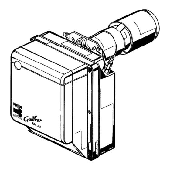
Öl-Gebläsebrenner
D
Brûleurs fioul
F
Light oil burners
GB
Funzionamento monostadio
Einstufiger Betrieb
Fonctionnement à 1 allure
One stage operation
CODICE
CODE
3737050
3737055
3737056
3737450
3737455
All manuals and user guides at all-guides.com
MODELLO - MODELL
MODELE - MODEL
BGK1
BGK1
BGK1
BGK2
BGK2
TIPO - TYP
TYPE
370 T1
370 T1
370 T1
374 T1
374 T1
2902323 (8)
Kapitel
Inhaltsverzeichnis

Verwandte Anleitungen für Riello 3737050


Inhaltszusammenfassung für Riello 3737050
- Seite 1 Light oil burners Funzionamento monostadio Einstufiger Betrieb Fonctionnement à 1 allure One stage operation CODICE MODELLO - MODELL TIPO - TYP CODE MODELE - MODEL TYPE 3737050 BGK1 370 T1 3737055 BGK1 370 T1 3737056 BGK1 370 T1 3737450 BGK2...
- Seite 2 All manuals and user guides at all-guides.com Dichiarazione del produttore secondo la normativa 1. BImSchV, 1996 RIELLO S.p.A. dichiara che i seguenti prodotti rispettano i valori limite degli NOx imposti dalla normativa 1. BImSchV, 1996, § 7 (2): Herstellerbescheinigung gemäß 1. BImSchV, 1996 RIELLO S.p.A.
-
Seite 13: Beschreibung Des Brenners
All manuals and user guides at all-guides.com INHALT BESCHREIBUNG DES BRENNERS . . . BETRIEB ......1.1 Mitgeliefertes Zubehör ....4.1 Einstellung der Brennerleistung. -
Seite 14: Technische Merkmale
All manuals and user guides at all-guides.com 2. TECHNISCHE MERKMALE 2.1 TECHNISCHE DATEN 370T1 374T1 ÷ ÷ Durchsatz kg/h Nach ÷ ÷ EN 267 Brennerleistung 17,8 35,6 59,3 ÷ ÷ Durchsatz kg/h 1,52 2,95 Nach ÷ ÷ LRV 92 Brennerleistung ÷... -
Seite 15: Installation
All manuals and user guides at all-guides.com 3. INSTALLATION DIE INSTALLATION DES BRENNERS MUSS IN ÜBEREINSTIMMUNG MIT DEN ÖRTLICHEN GESETZEN UND VORSCHRIFTEN AUSGEFÜHRT WERDEN. 3.1 BRENNERMONTAGE Die Schraube und die beiden Muttern am Flansch (1) montieren (siehe Abb. 3). Falls erforderlich, die Bohrungen der Isolierdichtung (5) erweitern (siehe Abb. 4). Mit den Schrauben (2) und (falls erforderlich) den Muttern (3) den Flansch (1) an der Kesseltür (4) mit Isolierdichtung (5) montieren (siehe Abb. -
Seite 16: Ölversorgungsanlage
All manuals and user guides at all-guides.com 3.3 ÖLVERSORGUNGSANLAGE WICHTIGER HINWEIS: Abb. 7 Die Pumpe ist werksseitig für den Zweirohr-Betrieb einge- richtet. Wird ein Pumpen-Einrohrbetrieb für notwendig erachtet, so ist der Rücklauf-Schlauchleitungsstopfen (2) zu lösen und die By-Pass Schraube (3) zu entfernen. Danach ist der Rücklauf-Schlauchleitungsstopfen wieder einzuschrauben. -
Seite 17: Elektrisches Verdrahtungsschema
All manuals and user guides at all-guides.com 3.4 ELEKTRISCHES VERDRAHTUNGSSCHEMA ANMERKUNGEN: WICHTIGER HINWEIS – Leiterdurchmesser: min. 1 mm . (Außer im NULLEITER NICHT MIT DER PHASE VERWECHSELN Falle anderslautender Angaben durch Normen 230V 50Hz und örtliche Gesetze). – Die vom Installateur ausgeführten elektrischen Verbindungen müssen den lokalen Bestim- mungen entsprechen . -
Seite 18: Betrieb
All manuals and user guides at all-guides.com 4. BETRIEB 4.1 EINSTELLUNG DER BRENNERLEISTUNG In Konformität mit der Wirkungsgradrichtlinie 92/42/EWG müssen die Anbringung des Brenners am Heizkessel, die Einstellung und die Inbetriebnahme unter Beachtung der Betriebsanleitung des Heizkessels ausgeführt werden, einschließlich Kontrolle der Konzentration von CO und CO in den Abgasen, der abgastemperatur und der mittleren Kesseltemperatur. -
Seite 19: Brennerkopfeinstellung
All manuals and user guides at all-guides.com Abb. 12 – Den Düsenstock (1) herausneh- men, nachdem vorher die Schrauben (2) gelok- kert, die Mutter (3) gelöst, die Zündkabel (4) vom Steuergerät, die Steckdose (5) und den Flammendetektor (6) abgenommen wurden. –... -
Seite 20: Elektrodeneinstellung
All manuals and user guides at all-guides.com 4.2 ELEKTRODENEINSTELLUNG (siehe Abb. 15) WICHTIGER HINWEIS 5,5 ± 0,3 mm – 0,5 mm DIE ABSTÄNDE MÜSSEN EINGE- Abb. 15 HALTEN WERDEN. Setzen den Stauscheibenhalter-System (1) gegen den Düsenstock (2) und befe- stige ihn mit der Schraube (3). Für eventuelle Einstellungen des Elektro- denpaares (4), die Schraube (5) lösen. -
Seite 21: Betriebsablauf
All manuals and user guides at all-guides.com 4.5 BETRIEBSABLAUF Störabschaltung wegen Störabschaltung Normal Nichtzündung wegen Nichtabschaltens Thermostat Vorwärmer Motor Zündtransformator Ventil Flamme Störlampe Störabschaltung ÷ ÷ ÷ ÷ wegen nicht erfolgter 150s 150s 150s Zündung D5197 Wird durch die Kontrollampe am Steuer- und Überwachungsgerät signalisiert (6, Abb. 1, S. 1). In diesem Fall fährt der Brenner nicht wieder an, da eine besonders schwerwiegende Störung vorliegt. -
Seite 22: Störungen / Abhilfe
All manuals and user guides at all-guides.com 6. STÖRUNGEN / ABHILFE Nachfolgend finden Sie einige denkbare Ursachen und Abhilfemöglichkeiten für Störungen, die den Betrieb des Brenners beeinflussen oder einen nicht ordnungsgemäßen Betrieb des Brenners verursachen könnten. In den meisten Fällen führt eine Störung zum Aufleuchten der Kontrolleuchte in der Entstörtaste des Steuerge- räts (Pos.