
Verwandte Anleitungen für Tecno-gaz Master Flux


Inhaltszusammenfassung für Tecno-gaz Master Flux
- Seite 1 All manuals and user guides at all-guides.com Istruzioni per l’uso ITALIANO Instructions for use ENGLISH Mode d’emploi FRANCAIS 0ZMFI0003 - 10.01.2013 Bedienungsanleitung DEUTSCH...
- Seite 2 All manuals and user guides at all-guides.com Questo apparecchio assolve ai criteri di conformità CE in quanto conforme alla direttiva 93/42/CEE. La dichiarazione di conformità originale è fornita in allegato al manuale. 0051 This device compliance to Directive 93/42/CE. The original declaration of confirmity is provided in attached to the manual.
- Seite 3 SICUREZZA MARCATURA DI SICUREZZA DISPOSITIVI DI SICUREZZA SMALTIMENTO DATI TECNICI DISINBALLAGGIO COMPONENTI INSTALLAZIONE INSTALLAZIONE MASTER FLUX A MOBILE INSTALLAZIONE MASTER FLUX A PARETE COLLEGAMENTO CIRCUITI E ACCESSORI EVACUAZIONE GAS ESALATI FUNZIONAMENTO DEL DISPOSITIVO PLANCIA COMANDI ISTRUZIONI DI UTILIZZO MANUTENZIONE PULIZIA...
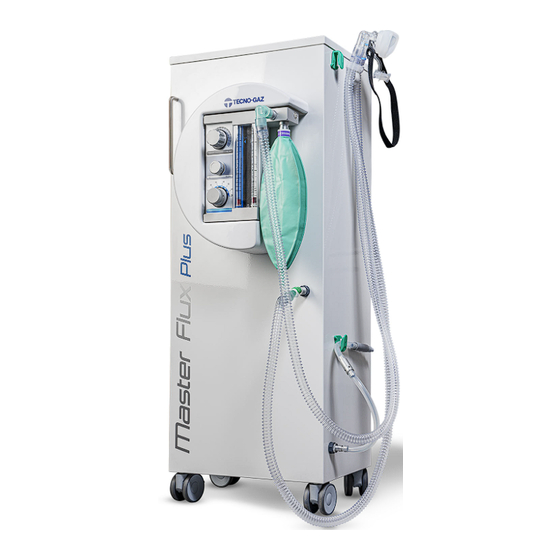
- Seite 4 IMPIEGO E DESTINAZIONE D’USO DESTINAZIONE D’USO Master Flux è un Dispositivo studiato per la sedazione cosciente o analgesia sedativa. La sedazione cosciente consiste nel somministrare al paziente una miscela di protossido di azoto e ossigeno, con una concentrazione massima di protossido di azoto del 70%.
-
Seite 5: Smaltimento
All manuals and user guides at all-guides.com ITALIANO SICUREZZA Marcatura di sicurezza Il dispositivo è conforme alla Direttiva 93/42 CEE modifiche e integrazioni. La dichiarazione è allegata al dispositivo. Dispositivi di sicurezza Il dispositivo è fornito di dispositivi di sicurezza: Se si riduce la pressione dell’ossigeno (O ), l’erogazione di protossido di azoto (N si interrompe automaticamente. - Seite 6 42 Kg Peso con bombole capacità 5 Lt 63 Kg (bombole vuote) Peso con bombole capacità 10 Lt: 81 Kg (bombole vuote) BOMBOLE PER MASTER FLUX A MOBILE: Altezza massima 950 mm Diametro massimo 140 mm PESO MASTER FLUX A PARETE: Peso della scatola flussometrica 6.27Kg...
- Seite 7 All manuals and user guides at all-guides.com ITALIANO UNITS ( MM ) Figura A1 (max) 400 Figura A2...
- Seite 8 Togliere l’imballo e controllare lo stato dell’apparecchio. I dispositivi imballati devono essere custoditi in luoghi asciutti e a temperatura compresa tra +5 / +40 °C. NON È CONSENTITA SOVRAPPORE I MOBILI MASTER FLUX COMPONENTI VARIANTI PREVISTE: A MOBILE...
- Seite 9 All manuals and user guides at all-guides.com ITALIANO SMFA223 DISTANZIATORE CM25021 VITE AD ALETTE M5 SMFA178 DISTANZIATORE CM20015 RONDELLA CM25019 DADO AD ALETTE M6 SMFA237 PORTAGOMMA ELIMINAZIONE GAS SMFA365 TUBO N2O SMFA364 TOBO O2 SMFA313 PERNO SMFA501 PIATRA A PARETE SMFA301 SUPPORTO A PARETE CM30011...
- Seite 10 INSTALLAZIONE Togliere l’imballo e controllare lo stato dell’apparecchio. Non utilizzare apparecchi che presentano danni evidenti dovuti al trasporto. Installazione master flux a mobile ( art. 1500/AS e 1600AS ) Figura A3 MONTAGGIO SCATOLA FLUSSOMETRICA (FIGURA A3) Avvitare i 3 distanziatori in acciaio (3) sulla scatola flussometrica (2).
- Seite 11 All manuals and user guides at all-guides.com ITALIANO MONTAGGIO COVER FRONTALE Posizionare la cover in plastica in prossimità dei tre fori sul mobile. Fissare la cover in plastica avvitando le tre viti ad alette (4) in dotazione. MONTAGGIO PORTAGOMMA SCARICO Se si utilizza il tubo di scarico dei gas esalati (figura A4 art SMFA197) , avvitare i portagomma, in dotazione, ai raccordi in plastica (8, figura A3).
- Seite 12 All manuals and user guides at all-guides.com ITALIANO Art.1605A Art.1606A Art.1607A Figura A5...
-
Seite 13: Montaggio Bombole (Non In Dotazione) (Figura A6)
All manuals and user guides at all-guides.com ITALIANO 5 lt 5 lt 10 lt 10 lt 14 lt 14 lt Figura A6 MONTAGGIO BOMBOLE (NON IN DOTAZIONE) (FIGURA A6) Fissare i riduttori alle bombole (vedi manuale istruzione dei riduttori). Per bombole da 5 lt inserire il ripiano (16) e fissarlo tramite gli appositi fermi. - Seite 14 All manuals and user guides at all-guides.com ITALIANO Installazione master flux a parete ( art. 1501/AS e 1601AS ) Figura A7...
- Seite 15 Figura A8 (FIGURA A7-A8) Fissare il SUPPORTO Master Flux a parete (13) utilizzando n.4 tasselli per parete Ø14 mm Fissare la PIASTRA Master Flux a parete (12) con n.4 tasselli per parete Ø 8(mm). Avvitare alla base della scatola flussometrica il perno (11).
- Seite 16 All manuals and user guides at all-guides.com ITALIANO NOTE SULL’IMPIANTO CENTALIZZATO L’installazione deve essere eseguita da tecnici specializzati, l’impianto centralizzato deve essere eseguito in conformità alle direttive vigenti Direttiva Europea 93/42/CE Collegare la presa a parete al punto equipotenziale dell’impianto elettrico, con i connettori a occhiello in dotazione.
- Seite 17 I kit maschere vengono collegati al dispositivo, tramite il portagomma (H). I kit si differenziano in relazione alla versione del dispositivo acquistato: MASTER FLUX - Art. 1500/AS e 1501/AS MASTER FLUX PLUS - Art. 1600/AS e 1601/AS Collegare il tubo spiralato (26) al portagomma (H).
- Seite 18 Lo scarico dell’aspiratore deve essere esterno e areato. Verificare la conformità alle normative vigenti nel paese di utilizzo. Collegamento diretto all’esterno dello studio MASTER FLUX A MOBILE - Art. 1500/AS e 1600AS Avvitare i portagomma (8 - figura A3) al mobile. Art. 1500/AS Art.
- Seite 19 All manuals and user guides at all-guides.com ITALIANO Collegamento all’aspiratore chirurgico Art. 1500/AS e 1501/AS Art. 1600/AS e 1601/AS Collegare il tubo scarico gas del circuito Collegare il tubo scarico gas del circuito maschera, al raccordo (34 - figura A4) in maschera, alla valvola (31M - figura A5) in dotazione.
- Seite 20 All manuals and user guides at all-guides.com ITALIANO FUNZIONAMENTO DEL DISPOSITIVO Plancia comandi Figura A10 TASTI COMANDO (FIGURA A10) REGOLAZIONE FLUSSO EROGATO REGOLAZIONE % MISCELA PROTOSSIDO DI AZOTO PULSANTE DI EMERGENZA ELEMENTI DI CONTROLLO FLUSSO PROTOSSIDO DI AZOTO PURO FLUSSO OSSIGENO PURO PALLONE (VERIFICA - FLUSSO IDONEO AL PAZIENTE)
-
Seite 21: Istruzioni Di Utilizzo
All manuals and user guides at all-guides.com ITALIANO Istruzioni di utilizzo Aprire LENTAMENTE le valvole delle bombole O O (ruotare in senso antiorario i rubinetti). Leggere la pressione sui manometri dei riduttori di pressione, (vedi DATI TECNICI) per stimare l’autonomia della bombola di ossigeno. Scegliere la mascherina idonea al paziente. -
Seite 22: Specifiche Di Terapia Per Bambini
All manuals and user guides at all-guides.com ITALIANO Determinato il flusso ideale, determinato dalla capacità polmonare del paziente, regolare la valvola di eliminazione gas come indicato nel paragrafo 6.4 ‘Evacuazione gas esalati’. Con la manopola % (C – figura A10) è possibile variare la percentuale di protossido di azoto. - Seite 23 Chiudere il rubinetto della bombola dell’Ossigeno (02), (ruotando il senso orario). STABILITA’ DURANTE L’USO: Prima di iniziare ad utilizzare il dispositivo MASTER FLUX nella versione a mobile, bloccare le ruote munite di freno premendo verso il basso le apposite linguette.
- Seite 24 (ruotare in senso orario il rubinetto). Togliere il kit maschera dal Master Flux sfilandolo dal tubo spiralato. Inserire nel tubo spiralato, l’apposito raccordo (25). Collegare l’estremità del tubo per ossigeno terapia (24) al raccordo (25).
- Seite 25 Pulire le superfici del dispositivo con panno asciutto. Prima e dopo l’utilizzo pulire, detergere o sterilizzare i particolari a contatto con il paziente o con il suo respiro. Tabella della pulizia dei componenti MASTER FLUX STERILIZZAZIONE DISINFEZIONE STERILIZZAZIONE FIG/POS MATERIALE...
- Seite 26 All manuals and user guides at all-guides.com ITALIANO RACCORDO COLLEGAMENTO 121°C A4/29 SCARICO (NON IMBUSTATO) ASPIRATORE (SMFA229) BLOCCATUBO A 121°C A4/42 SCORSOIO (NON IMBUSTATO) (SMFA231) CIRCUITI MATRIX (IN DOTAZIONE AL 1600/AS E 1601AS) VALVOLA MATRIX A5/31M (1615A) MASCHERA 1605A MATRIX (adulto) A5/17M...
-
Seite 27: Manutenzione Programmata
Prima di ogni utilizzo controllare che il PALLONE, IL TUBO SPIRALATO e il KIT MASCHERE siano integri. Nel caso il MASTER FLUX rimanga fermo per più di un mese, eseguire un controllo funzionale. MASTER FLUX OGNI 24 MESI D’UTILIZZO O IN CASO DI FUNZIONAMENTO ANOMALO CONTATTARE IL... - Seite 28 Riduttore di pressione non Sostituire il riduttore Non eroga ossigeno funzionante Problemi interni alla scatola Controllo del dispositivo presso flussometrica Tecno-gaz Mancanza di ossigeno Caricare la bombola Non eroga protossido di azoto Riduttore di pressione non Sostituire il riduttore funzionante Azzerare la manopola ‘FLOW’...
- Seite 29 All manuals and user guides at all-guides.com ITALIANO PROCEDURE PER SERVIZIO ED ASSISTENZA In caso di guasto o revisione contattare direttamente l’assistenza telefonica MEDILINE ITALIA s.r.l. PHONE +39 0522 94.29.96 +39 0522 94.47.98 service@tecnogaz.com Sarà l’assistenza a valutare il rientro in sede o l’intervento di un tecnico e visionata la macchina a stilare un preventivo di spesa, che verrà...
- Seite 30 All manuals and user guides at all-guides.com ITALIANO ACCESSORI CIRCUITI TECNO-GAZ (IN DOTAZIONE AL 1500/AS E 1501/AS) FIG/POS Q.TA’ CODICE DESCRIZIONE A4/27 RACCORDO – SMFA228 A4/28 TUBO – SMFA240 L= 130cm A4/29 INNESTO TUBO MASCHERA – SMFA229 MASCHERA...
-
Seite 31: Inhaltsverzeichnis
SAFETY SAFETY MARKING SAFETY DEVICES DISPOSAL TECHNICAL DATA UNPACKING COMPONENTS INSTALLATION INSTALLATION OF UNIT-MOUNTED MASTER FLUX INSTALLATION OF WALL-MOUNTED MASTER FLUX CONNECTING CIRCUITS AND ACCESSORIES EVACUATION OF EXHALED GASES OPERATION OF THE APPLIANCE CONTROL PANEL INSTRUCTIONS FOR USE MAINTENANCE CLEANING... -
Seite 32: Utilisation And Intended Use
UTILISATION AND INTENDED USE INTENDED USE Master Flux is a device designed for conscious sedation or sedative analgesia. Conscious sedation consists in administering a mixture of nitrous oxide and oxygen to the patient, at a maximum concentration of nitrous oxide of 70%. -
Seite 33: Safety
All manuals and user guides at all-guides.com ENGLISH SAFETY Safety marking The device complies with Directive 93/42 EEC as amended. The declaration is provided in attachment to the device. Safety devices The device is fitted with safety devices: If the oxygen (O ) pressure drops, the delivery of nitrous oxide (N O) is automatically shut off. -
Seite 34: Technical Data
Weight without cylinders 42 Kg Weight with 5 Lt cylinders 63 Kg (empty cylinders) Weight with 10 Lt cylinders: 81 Kg (empty cylinders) CYLINDERS FOR UNIT-MOUNTED MASTER FLUX: Maximum height 950 mm Maximum diameter 140 mm WEIGHT WALL-MOUNTED MASTER FLUX: Weight of the flowmeter box 6.27Kg... - Seite 35 All manuals and user guides at all-guides.com ENGLISH UNITS ( MM ) Figure A1 (max) 400 Figure A2...
-
Seite 36: Unpacking
Remove the packaging and check the appliance condition. The devices must be kept safe in a dry location and at a temperature between +5 / +40 °C. IT IS FORBIDDEN TO STACK MASTER FLUX UNITS DESCRIPTION OF COMPONENTS... - Seite 37 All manuals and user guides at all-guides.com ENGLISH CM25021 M5 THUMB SCREW SMFA178 SPACER CM20015 WASHER CM25019 M6 THUMB NUT SMFA237 GAS EXTRACTION NOZZLE SMFA365 N2O TUBE SMFA364 02 TUBE SMFA313 SMFA501 WALL PLATE SMFA301 WALL-MOUNTED SUPPORT CM30011 PIN SECURING KNOB 1513A4 O2 REDUCER 1515/A3...
-
Seite 38: Installation
Remove the packaging and check the conditions of the equipment. Do not use equipment that presents evident damage due to transportation. Installation of unit-mounted master flux ( art. 1500/AS and 1600AS ) Figure A3 FLOWMETER BOX INSTALLATION (FIGURE A3) Screw the 3 steel spacers (3) onto the flowmeter box (2). - Seite 39 All manuals and user guides at all-guides.com ENGLISH FRONT COVER INSTALLATION Position the plastic cover near the three holes on the unit. Attach the plastic cover by screwing on the three thumb screws (4) supplied. EXHAUST NOZZLE INSTALLATION If you are using the exhaled gas exhaust tube (figure A4 art SMFA197), screw the supplied nozzles onto the plastic fittings (8, figure A3).
- Seite 40 All manuals and user guides at all-guides.com ENGLISH Art.1605A Art.1606A Art.1607A Figure A5...
- Seite 41 All manuals and user guides at all-guides.com ENGLISH 5 lt 5 lt 10 lt 10 lt 14 lt 14 lt Figure A6 CYLINDER INSTALLATION (NOT SUPPLIED) (FIGURE A6) Attach the reducers to the cylinders (see instruction manual for reducers). For 5 lit cylinders install the shelf (16) and attach it using the relative shelf stops.
-
Seite 42: Installation Of Wall-Mounted Master Flux
All manuals and user guides at all-guides.com ENGLISH Installation of wall-mounted master flux (art. 1501/AS and 1601AS) Figure A7... - Seite 43 Figure A8 (FIGURE A7-A8) Attach the Master Flux SUPPORT to the wall (13) using 4 Ø14 mm M8 wall dowels. Attach the Master Flux PLATE to the wall (12) using 4 Ø 8(mm) wall dowels. Screw the pin (11) onto the base of the flowmeter box.
- Seite 44 All manuals and user guides at all-guides.com ENGLISH NOTES ON THE CENTRALISED SYSTEM Installation must be carried out by specialised technicians. The centralised system must be set up in compliance with regulations in force European Directive 93/42/EC Connect the wall outlet to the equipotential point on the electrical system, with the supplied loop connectors.
-
Seite 45: Connecting Circuits And Accessories
The mask kits are connected to the device by the nozzle (H). The kits differ based on the version of the acquired device: MASTER FLUX - Art. 1500/AS and MASTER FLUX PLUS - Art. 1600/AS and 1501/AS 1601/AS Connect the spiral tube (26) to the nozzle Connect the gas supply tube for the mask (H). -
Seite 46: Evacuation Of Exhaled Gases
Make sure it is compliant with regulations in force in the country of use. Direct connection to the outside of the office UNIT-MOUNTED MASTER FLUX - Art. 1500/AS and 1600AS Screw the nozzles (8 - figure A3) onto the unit. - Seite 47 All manuals and user guides at all-guides.com ENGLISH Connection to a surgical aspirator Art. 1500/AS and 1501/AS Art. 1600/AS and 1601/AS Connect the mask circuit gas exhaust tube Connect the mask circuit gas exhaust tube to the supplied fitting (29 - figure A4). to the supplied valve (31M - figure A5).
-
Seite 48: Operation Of The Appliance
All manuals and user guides at all-guides.com ENGLISH OPERATION OF THE APPLIANCE Control panel Figure A10 CONTROL KEYS (FIGURE A10) FLOW DELIVERY ADJUSTMENT ADJUSTMENT OF % OF NITROUS OXIDE MIXTURE EMERGENCY BUTTON CONTROL DEVICES PURE NITROUS OXIDE FLOW PURE OXYGEN FLOW BAG (CHECK - SUITABLE FLOW TO PATIENT) -
Seite 49: Instructions For Use
All manuals and user guides at all-guides.com ENGLISH INSTRUCTIONS FOR USE SLOWLY open the valves on the O and N O cylinders (turn the valves counter- clockwise). Read the pressure on the pressure reducer pressure gauges, (see TECHNICAL DATA) to estimate the autonomy of the oxygen cylinder. - Seite 50 All manuals and user guides at all-guides.com ENGLISH Once the ideal flow and the pulmonary capacity of the patient have been determined, adjust the gas elimination valve as explained in paragraph 6.4 ‘Evacuation of exhaled gases’. It is possible to change the percentage of nitrous oxide using the % knob (C – figure A10).
-
Seite 51: End Of Treatment
When using MASTER FLUX in its wall-mounted version, it is possible to move and position the flowmeter box as required by gripping the relative handle. - Seite 52 SLOWLY open the oxygen cylinder valve (turn the valve counter-clockwise); make sure that the nitrous oxide cylinder is closed (turn the valve clockwise). Take the Master Flux mask kit off by sliding it off of the spiral tube. Insert the relative fitting (25) into the spiral tube.
-
Seite 53: Maintenance
Clean the surfaces of the device with a dry cloth. Before and after use clean, wipe or sterilise the parts that come into contact with the patient or his/her breath. Cleaning table for MASTER FLUX parts DISINFECTION STERILISATION STEAM... - Seite 54 All manuals and user guides at all-guides.com ENGLISH FITTING (SMFA257) ASPIRATOR EXHAUST A4/29 CONNECTION (NOT PACKAGED) FITTING (SMFA229) TUBE SECURING LOOP ON A4/42 HEADREST (NOT PACKAGED) (SMFA231) MATRIX CIRCUITS (SUPPLIED WITH 1600/AS AND 1601AS) MATRIX VALVE A5/31M (1615A) 1605A MATRIX MASK (adult) 1611A(adult)
-
Seite 55: Scheduled Maintenance
Scheduled maintenance Before each use make sure that the BAG, SPIRAL TUBE and MASK KIT are intact. If MASTER FLUX is not used for over a month carry out an operational check. MASTER FLUX EVERY 24 MONTHS OF USE OR IN CASE OF FAULTY OPERATION CONTACT THE DEALER... -
Seite 56: Alarms
All manuals and user guides at all-guides.com ENGLISH ALARMS SITUATIONS THAT MAY ARISE DURING OPERATION: Problems Possible causes Solution Empty cylinder Re-charge the cylinder It does not deliver Pressure reducer not working Change the reducer oxygen Have the device checked by Tecno- Problems inside the flowmeter box No oxygen Charge the cylinder... -
Seite 57: Procedures For After Sale Service
All manuals and user guides at all-guides.com ENGLISH PROCEDURES FOR AFTER SALE SERVICE In case of damage or for overhaul contact directly the phone service of MEDILINE ITALIA s.r.l. PHONE +39 0522 94.29.96 +39 0522 94.47.98 service@tecnogaz.com The service staff shall decide whether the return to the manufacturer or the intervention of a technician is necessary;... - Seite 58 All manuals and user guides at all-guides.com ENGLISH ACCESSORIES TECNO-GAZ CIRCUITS(SUPPLIED WITH 1500/AS AND 1501/AS) FIG/POS Q.TY CODE DESCRIPTION A4/27 FITTING – SMFA228 A4/28 TUBE – SMFA240 L= 130cm A4/29 MASK TUBE COUPLING – SMFA229 MASK A4/30 1524-A...
- Seite 59 MARQUAGE DE SECURITE DISPOSITIFS DE SECURITE ECOULEMENT DONNES TECHNIQUES DESEMBALLAGE COMPOSANTS INSTALLATION 6.1 INSTALLATION MASTER FLUX SUR MEUBLE INSTALLATION MASTER FLUX MURALE RACCORDEMENT DES CIRCUITS ET DES ACCESSOIRES EVACUATION DES GAZ EXHALES FONCTIONNEMENT DE L’APPAREIL TABLEAU DES COMMANDES MODE D’EMPLOI...
-
Seite 60: Utilisation Et Usage Prevu
UTILISATION ET USAGE PREVU USAGE PREVU Master Flux est un Dispositif étudié pour la sédation consciente ou l'analgésie sédative. La sédation consciente consiste à administrer au patient un mélange de protoxyde d'azote et d'oxygène avec une concentration maximum de protoxyde d'azote de 70%. -
Seite 61: Securite
All manuals and user guides at all-guides.com FRANÇAIS SECURITE Marquage de sécurité Le dispositif est conforme à la Directive 93/42 CEE modifications et intégrations. La déclaration est annexée au dispositif. Dispositifs de sécurité Le dispositif est équipé de dispositifs de sécurité: Si l'on réduit la pression de l'oxygène (O ), la distribution du protoxyde d'azote (N s'interrompt automatiquement. -
Seite 62: Donnes Techniques
3.5 bars 50 PSI (max 6 bars 87 PSI) Débit maximum 10 l/min. (litres à la minute) POIDS DU MASTER FLUX SUR MEUBLE: Poids sans bouteilles 42 Kg Poids avec bouteille d'une 63 Kg (bouteilles vides) contenance de 5 l... - Seite 63 All manuals and user guides at all-guides.com FRANÇAIS UNITS ( MM ) Figure A1 (max) 400 Figure A2...
-
Seite 64: Desemballage
Enlever l’emballage et contrôler l'état de l’appareil. Les dispositifs emballés doivent être conservés dans des lieux secs et à une température comprise entre + 5/+ 40 °C. IL N'EST PAS AUTORISE DE SUPERPOSER LES MEUBLES MASTER FLUX DESCRIPTION DES COMPOSANTS... - Seite 65 All manuals and user guides at all-guides.com FRANÇAIS SMFA223 ECARTEUR CM25021 VIS A AILETTES M5 SMFA178 ECARTEUR CM20015 RONDELLE CM25019 ECROU A AILETTES M6 SMFA237 EMBOUT D'ELIMINATION DE GAZ SMFA365 TUYAU N2O SMFA364 TUYAU O2 SMFA313 PIVOT SMFA501 PLAQUE MURALE SMFA301 SUPPORT MURAL CM30011...
-
Seite 66: Installation
Enlever l'emballage et contrôler l'état de l'appareil. Ne pas utiliser des appareils qui présentent des dommages évidents dus au transport. Installation de master flux sur meuble (art. 1500/AS et 1600AS) Figure A3 MONTAGE DU BOITIER FLUXMETRIQUE (FIGURE A3) Visser les 3 écarteurs en acier (3) sur le boîtier débitmétrique (2). - Seite 67 All manuals and user guides at all-guides.com FRANÇAIS MONTAGE DE LA COUVERTURE FRONTALE Positionner la couverture en plastique à proximité des trois trous qui se trouvent sur le meuble. Fixer la couverture en plastique en serrant les trois vis à ailettes (4) fournies. MONTAGE DE L'EMBOUT D'EVACUATION Si l'on utilise le tuyau d'évacuation des gaz exhalés (figure A4 art SMFA197), serrer l'embout fourni aux raccords en plastique (8, figure A3).
- Seite 68 All manuals and user guides at all-guides.com FRANÇAIS Art.1605A Art.1606A Art.1607A Figure A5...
- Seite 69 All manuals and user guides at all-guides.com FRANÇAIS 5 lt 5 lt 10 lt 10 lt 14 lt 14 lt Figure A6 MONTAGE DES BOUTEILLES (NON FOURNIES) (FIGURE A6) Fixer les réducteurs sur les bouteilles (voir le manuel d'instruction des réducteurs). Pour les bouteilles de 5 l mettre l'étagère (16) et la fixer par l'intermédiaire des arrêts prévus à...
-
Seite 70: Installation Master Flux Murale
All manuals and user guides at all-guides.com FRANÇAIS Installation de master flux mural (art. 1501/AS et 1601AS) Figure A7... - Seite 71 Figure A8 (FIGURE A7-A8) Fixer le SUPPORT Master Flux sur le mur (13) en utilisant 4 tasseaux pour mur Ø14 mm Fixer la PLAQUE Master Flux sur le mur (12) avec 4 tasseaux pour mur Ø 8(mm). Visser à la base du boîtier débitmétrique le pivot (11).
- Seite 72 All manuals and user guides at all-guides.com FRANÇAIS REMARQUES SUR L'INSTALLATION CENTRALISEE L'installation doit être effectuée par des techniciens spécialisés, l'installation centralisée doit être effectuée conformément aux directives en vigueur Directive Européenne 93/42/CE Raccorder la prise murale au point équipotentiel de l'installation électrique avec les connecteurs à...
-
Seite 73: Raccordement Des Circuits Et Des Accessoires
Les kits des masques sont raccordés au dispositif au moyen de l'embout (H). Les kits se différencient en fonction de la version du dispositif acheté: MASTER FLUX - Art. 1500/AS et 1501/AS MASTER FLUX PLUS - Art. 1600/AS et 1601/AS Raccorder le tuyau spiralé... -
Seite 74: Evacuation Des Gaz Exhales
L'évacuation de l'aspirateur doit être extérieure et aérée. Vérifier la conformité des réglementations en vigueur dans le pays d'utilisation. Le raccordement direct à l'extérieur du cabinet MASTER FLUX SUR MEUBLE - Art. 1500/AS et 1600AS Visser l'embout (8 - figure A3) sur le meuble. Art. 1500/AS Art. - Seite 75 All manuals and user guides at all-guides.com FRANÇAIS Raccordement à l'aspirateur chirurgical Art. 1500/AS et 1501/AS Art. 1600/AS et 1601/AS Raccorder le tuyau d'évacuation de gaz du Raccorder le tuyau d'évacuation de gaz du circuit du masque au raccord (29 - figure circuit du masque à...
-
Seite 76: Fonctionnement De L'appareil
All manuals and user guides at all-guides.com FRANÇAIS FONCTIONNEMENT DE L'APPAREIL Tableau des commandes Figure A10 TOUCHES COMMANDE (FIGURA A10) REGLAGE DU FLUX DISTRIBUE REGLAGE % MELANGE PROTOXYDE D'AZOTE BOUTON D'URGENCE ELEMENTS DE CONTROLE FLUX PROTOXYDE D'AZOTE PUR FLUX D'OXYGENE PUR BALLON (VERIFICATION - FLUX ADAPTE AU PATIENT) -
Seite 77: Mode D'emploi
All manuals and user guides at all-guides.com FRANÇAIS Mode d’emploi Ouvrir LENTEMENT les soupapes des bouteilles O et N O (tourner dans le sens antihoraire les robinets). Lire la pression sur les manomètres des réducteurs de pression, (voir DONNEES TECHNIQUES) pour estimer l'autonomie de la bouteille d'oxygène. - Seite 78 All manuals and user guides at all-guides.com FRANÇAIS Lorsque le flux idéal est déterminé par la capacité pulmonaire du patient, régler la soupape d'élimination de gaz comme indiqué au paragraphe 6.4 ‘Evacuation des gaz exhalés'. Avec le bouton sélecteur % (C – figure A10) il est possible de changer le pourcentage de protoxyde d'azote.
- Seite 79 à cet effet et faire glisser le dispositif, éviter des chocs et des mouvements brusques qui pourraient causer des chutes accidentelles. Lors de l'utilisation de MASTER FLUX dans la version murale, il est possible de déplacer et d'orienter le boîtier débitmétrique à souhait, en prenant la poignée prévue à cet effet.
- Seite 80 (tourner dans le sens horaire le robinet). Enlever le kit masque du Master Flux en l'enlevant du tuyau spiralé. Introduire dans le tuyau spiralé, le raccord correspondant (25).
-
Seite 81: Entretien
Nettoyer les surfaces du dispositif avec un chiffon sec. Avant et après l'utilisation nettoyer, déterger ou stériliser les parties en contact avec le patient ou avec sa respiration. Tableau du nettoyage des composants MASTER FLUX STERILISATION DESINFECTION STERILISATION A... - Seite 82 All manuals and user guides at all-guides.com FRANÇAIS (SMFA237) RACCORD DE BRANCHEMENT A4/34 EVACUATION (NON EMBALLE) MURALE (SMFA257) RACCORD DE BRANCHEMENT A4/29 EVACUATION DE (NON EMBALLE) L'ASPIRATEUR (SMFA229) BLOQUE-TUYAU A4/42 AUTOSERRANT (NON EMBALLE) (SMFA231) CIRCUITS MATRIX (FOURNI SUR 1600/AS ET 1601AS) SOUPAPE MATRIX A5/31M (1615A)
-
Seite 83: Entretien Programme
Avant toute utilisation, contrôler que le BALLON, LE TUYAU SPIRALE et le KIT DES MASQUES soient en bon état. Si le MASTER FLUX reste à l'arrêt pour une durée supérieure à un mois, effectuer un contrôle fonctionnel. MASTER FLUX... -
Seite 84: Signalisations
All manuals and user guides at all-guides.com FRANÇAIS SIGNALISATIONS SITUATIONS QUI PEUVENT ETRE VERIFIEES LORS DU FONCTIONNEMENT: Problèmes Causes possibles Remède Bouteille déchargée Charger la bouteille Réducteur de pression non Ne distribue pas Remplacer le réducteur fonctionnel d'oxygène Problèmes internes du boîtier Contrôle du dispositif chez Tecno- débitmétrique... -
Seite 85: Procedures Pour Le Service Et L'assistance
All manuals and user guides at all-guides.com FRANÇAIS PROCEDURES POUR LE SERVICE ET L’ASSISTANCE En cas de défaillance ou de révision contacter directement l’assistance après vente téléphonique MEDILINE ITALIA s.r.l. PHONE +39 0522 94.29.96 +39 0522 94.47.98 service@tecnogaz.com Ce sera le service d’assistance après vente à évaluer l'opportunité du retour à l'usine ou bien de l'intervention d'un technicien et, après avoir inspecté... -
Seite 86: Accessoires
All manuals and user guides at all-guides.com FRANÇAIS ACCESSOIRES CIRCUITS TECNO-GAZ (FOURNIS SUR 1500/AS ET 1501/AS) FIG/POS Q.TE CODE DESCRIPTION A4/27 RACCORD – SMFA228 A4/28 TUYAU – SMFA240 L= 130cm A4/29 RACCORD TUYAU MASQUE – SMFA229 MASQUE A4/30... - Seite 87 EINSATZ UND VERWENDUNGSZIEL DES GERÄTS SICHERHEIT SICHERHEITSMARKIERUNG SICHERHEITSVORRICHTUNGEN ENTSORGUNG TECHNISCHE DATEN AUSPACKEN BESTANDTEILE INSTALLATION INSTALLATION MASTER FLUX MOBIL INSTALLATION MASTER FLUX WANDAUSFÜHRUNG ANSCHLUSS DER LEITUNGEN UND DES ZUBEHÖRS ABFÜHRUNG AUSGEATMETER GASE BETRIEB DES GERÄTS STEUERBRETT GEBRAUCHSANLEITUNG WARTUNG REINIGUNG PROGRAMMIERTE WARTUNG...
-
Seite 88: Einsatz Und Verwendungsziel
EINSATZ UND VERWENDUNGSZIEL VERWENDUNGS-ZIEL Master Flux ist ein Gerät, das für die Wachnarkose bzw. sedative Analgesie entwickelt wurde. Die Wachnarkose besteht in der Verabreichung einer Mischung aus Stickoxidul und Sauerstoff an den Patienten, mit einer maximalen Stickoxidul-Konzentration von 70%. -
Seite 89: Sicherheit
All manuals and user guides at all-guides.com DEUTSCH SICHERHEIT Sicherheitsmarkierung Das Gerät erfüllt die Richtlinie 93/42 EWG inkl. Änderungen und Ergänzungen. Die Erklärung liegt dem Gerät bei. Sicherheitsvorrichtungen Das Gerät wird mit Sicherheitsvorrichtungen geliefert: Wenn der Druck des Sauerstoffs (O ) sinkt, wird die Zufuhr von Stickoxidul (N automatisch unterbrochen. -
Seite 90: Technische Daten
Versorgungsdruck 3.5 bar 50 PSI (max. 6 bar 87 PSI) Maximale Durchflussmenge 10 l/min (Liter pro Minute) GEWICHTE MASTER FLUX MOBIL: Gewicht ohne Gasflaschen 42 kg Gewicht mit 5-Liter-Gasflaschen 63 kg (leere Gasflaschen) Gewicht mit 10-Liter-Gasflaschen: 81 kg (leere Gasflaschen) GASFLASCHEN FÜR MASTER MOBIL:... - Seite 91 All manuals and user guides at all-guides.com DEUTSCH UNITS ( MM ) Abbildung A1 (max) 400 Abbildung A2...
-
Seite 92: Auspacken
Die Verpackung entfernen und den Gerätezustand kontrollieren. Die verpackten Geräte müssen trocken und bei Temperaturen zwischen +5 und +40 °C gelagert werden. DIE MASTER FLUX SCHRÄNKE DÜRFEN NICHT GESTAPELT WERDEN BESCHREIBUNG DER BESTANDTEILE VORGESEHENE VARIANTEN: MOBILE WANDAUSFÜHRUNG AUSFÜHRUNG... - Seite 93 All manuals and user guides at all-guides.com DEUTSCH SMFA223 ABSTANDHALTER CM25021 FLÜGELSCHRAUBE M5 SMFA178 ABSTANDHALTER CM20015 UNTERLEGSCHEIBE CM25019 FLÜGELMUTTER M6 SMFA237 SCHLAUCHTÜLLE GASABFÜHRUNG SMFA365 N2O-ROHR SMFA364 O2-ROHR SMFA313 ZAPFEN SMFA501 WANDPLATTE SMFA301 WANDHALTERUNG CM30011 ZAPFEN-SPANNSCHRAUBE 1513A4 O2-DRUCKMINDERER 1515/A3 N2O-DRUCKMINDERER SMFA173 ZWISCHENBODEN FÜR 5-L-FLASCHE A6-A9...
-
Seite 94: Installation
Verpackung entfernen und Zustand des Geräts überprüfen. Keine Geräte mit offensichtlichen, durch den Transport bedingten Schäden verwenden. Installation Master Flux Mobil (Art. 1500/AS und 1600AS) Abbildung A3 MONTAGE DES DURCHFLUSSMESSERS (ABBILDUNG A3) Abstandhalter aus Stahl (3) (3 x) an den Durchflussmesser (2) anschrauben. -
Seite 95: Montage Der Ableitungsschlauchtülle
All manuals and user guides at all-guides.com DEUTSCH MONTAGE DES FRONTCOVERS Kunststoff-Cover an den drei Bohrungen am Schrank positionieren. Kunststoff-Cover mit den drei mitgelieferten Flügelschrauben (4) befestigen. MONTAGE DER ABLEITUNGSSCHLAUCHTÜLLE Wenn der Schlauch zur Ableitung der ausgeatmeten Gase (Abbildung A4 Art. SMFA197) verwendet wird, die mitgelieferte Schlauchtülle an die Anschlussstücke aus Kunststoff (8, Abbildung A3) anschrauben. - Seite 96 All manuals and user guides at all-guides.com DEUTSCH Art.1605A Art.1606A Art.1607A Abbildung A5...
-
Seite 97: Montage Der Gasflaschen (Nicht Mitgeliefert) (Abbildung A6)
All manuals and user guides at all-guides.com DEUTSCH 5 lt 5 lt 10 lt 10 lt 14 lt 14 lt Abbildung A6 MONTAGE DER GASFLASCHEN (NICHT MITGELIEFERT) (ABBILDUNG A6) Druckminderer an den Gasflaschen anbringen (siehe Betriebsanleitung der Druckminderer). Für 5-Liter-Flaschen den Zwischenboden (16) einsetzen und mit den entsprechenden Halterungen fixieren. -
Seite 98: Installation Master Flux Wandausführung
All manuals and user guides at all-guides.com DEUTSCH Installation Master Flux Wandausführung (Art. 1501/AS und 1601AS) Abbildung A7... - Seite 99 Abbildung A8 (ABBILDUNG A7-A8) Master Flux WANDHALTERUNG (13) mit 4 Wanddübeln Ø14 mm M8 an der Wand fixieren. Master Flux WANDPLATTE (12) mit 4 Wanddübeln Ø 8 (mm) an der Wand befestigen. Zapfen (11) an die Basis des Durchflussmessers anschrauben.
- Seite 100 All manuals and user guides at all-guides.com DEUTSCH HINWEISE ZUR ZENTRALEN VERSORGUNGSANLAGE Die Installation muss durch spezialisierte Techniker ausgeführt werden, die zentrale Versorgungsanlage muss den geltenden Richtlinien entsprechen. Europäische Richtlinie 93/42/EG Wandanschluss mit den mitgelieferten Anschlussösen mit dem Potentialausgleich der Elektroanlage verbinden.
-
Seite 101: Anschluss Leitungen Und Zubehör
Schlauchtülle schieben. Die Maskensätze werden über die Schlauchtülle (H) mit dem Gerät verbunden. Die Sätze unterscheiden sich je nach Geräteversion: MASTER FLUX - Art. 1500/AS und MASTER FLUX PLUS - Art. 1600/AS und 1501/AS 1601/AS Spiralschlauch (26) an Schlauchtülle (H) Gaszufluss-Schlauch der Maske an anschließen. -
Seite 102: Abführung Ausgeatmeter Gase
Der Auslass der Absaugvorrichtung muss nach außen gehen und belüftet sein. Sicherstellen, dass die im Anwendungsland geltenden Vorschriften eingehalten werden. Direkte Verbindung nach außen MASTER FLUX MOBIL - Art. 1500/AS und 1600AS Schlauchtüllen (8 - Abbildung A3) am Schrank anschrauben. Art. 1500/AS Art. 1600AS... - Seite 103 All manuals and user guides at all-guides.com DEUTSCH Anschluss an die chirurgische Absaugvorrichtung Art. 1500/AS und 1501/AS Art. 1600/AS und 1601/AS Gasabfluss-Schlauch des Maskenkreises Gasabfluss-Schlauch des Maskenkreises mit dem mitgelieferten Anschlussstück (29 - mit dem mitgelieferten Ventil (31M - Abbildung A4) verbinden.
-
Seite 104: Betrieb Des Geräts
All manuals and user guides at all-guides.com DEUTSCH BETRIEB DES GERÄTS Steuerbrett Abbildung A10 BEDIENTASTEN (ABBILDUNG A10) REGELUNG DER AUSGABERATE REGELUNG %-ANTEIL STICKOXIDUL NOTFALL-TASTE KONTROLLELEMENTE FLUSSRATE REINES STICKOXIDUL FLUSSRATE REINER SAUERSTOFF BEUTEL (PRÜFUNG, OB FLUSSRATE FÜR PATIENTEN GEEIGNET) - Seite 105 All manuals and user guides at all-guides.com DEUTSCH Gebrauchsanleitung Ventile der O - und N O-Flaschen LANGSAM aufdrehen (Hähne gegen den Uhrzeigersinn drehen). Druck an den Manometern der Druckminderer ablesen (siehe TECHNISCHE DATEN), um die Autonomie der Sauerstoffflasche abzuschätzen. Für den Patienten geeignete Maske wählen.
-
Seite 106: Behandlungseinstellungen Für Kinder
All manuals and user guides at all-guides.com DEUTSCH Nach Bestimmung der idealen Flussrate, die durch das Lungenvolumen des Patienten gegeben ist, das Ventil zur Gasabführung wie in Abschnitt 6.4 Abführung ausgeatmeter Gase angegeben einstellen. Mit dem Reglerknopf % (C – Abbildung A10) kann der Stickoxidul-Anteil verändert werden. -
Seite 107: Schliessen Der Gasflaschen
Hahn der Stickoxidul-Flasche (N2O) schließen (im Uhrzeigersinn drehen). Hahn der Sauerstoff-Flasche (O2) schließen (im Uhrzeigersinn drehen). STABILITÄT WÄHREND DES GEBRAUCHS: Bevor das MASTER FLUX Gerät in der mobilen Ausführung benutzt wird, sind die Räder zu blockieren, die mit Bremse versehen sind, indem die entsprechenden Zungen nach unten gedrückt werden. -
Seite 108: Reanimation Mit Master Flux
DEUTSCH REANIMATION MIT MASTER FLUX SATZ Art. 1504/A (nicht mitgeliefert) (ABBILDUNG A11) Während der Ausführung der REANIMATION MIT MASTER FLUX muss der Reglerknopf (C – Abbildung A10) %N2O – Einstellung Prozentanteil Stickoxidul – auf 0% stehen. Ventil der Sauerstoffflasche LANGSAM aufdrehen (Hahn gegen den Uhrzeigersinn drehen), sicherstellen, dass die Stickoxidul-Flasche zugedreht ist (Hahn im Uhrzeigersinn drehen). -
Seite 109: Wartung
Oberflächen des Geräts mit einem trockenen Tuch reinigen. Vor und nach dem Gebrauch alle Teile, die mit dem Patienten oder seinem Atem in Berührung kommen, reinigen, abwischen oder sterilisieren. Tabelle zur Reinigung der MASTER FLUX Bestandteile DESINFEK- DAMPF- STERILISIE- TION MIT ABB./POS. - Seite 110 All manuals and user guides at all-guides.com DEUTSCH ABSAUGVORRICHTUNG (SMFA229) SCHIEBBARER 121°C A4/42 SCHLAUCHHALTER (UNVERPACKT) (SMFA231) MATRIX LEITUNGEN (MITGELIEFERT BEI 1600/AS UND 1601AS) A5/31M MATRIX VENTIL (1615A) 1605A MATRIX MASKE (Erw.) 1611A (Erw.) 1613A A5/17M 1607A (Kind) SIEHE DEN LEITUNGEN BEILIEGENDE ANWEISUNGEN 1612A (Jugendl.) (Kind) 1606A...
-
Seite 111: Programmierte Wartung
Programmierte Wartung Vor jedem Gebrauch den BEUTEL, den SPIRALSCHLAUCH und den MASKENSATZ auf Beschädigungen kontrollieren. Wird MASTER FLUX länger als einen Monat nicht benutzt, ist eine Funktionskontrolle durchzuführen. MASTER FLUX ALLE 24 MONATE BETRIEB BZW. BEI STÖRUNGEN DEN HÄNDLER VERSTÄNDIGEN, UM DAS GERÄT KONTROLLIEREN ZU LASSEN... -
Seite 112: Signale
Mögliche Ursachen Abhilfe Gasflasche leer Gasflasche auffüllen Keine Druckminderer funktioniert nicht Druckminderer austauschen Sauerstoffausgabe Probleme im Durchflussmesser Kontrolle des Geräts bei Tecno-gaz Sauerstoffmangel Gasflasche auffüllen Keine Stickoxidul- Ausgabe Druckminderer funktioniert nicht Druckminderer austauschen Reglerknopf „FLOW“ auf Null stellen Falsche Bedienung Ordnungsgemäßen Betrieb... -
Seite 113: Kundendienstverfahren
All manuals and user guides at all-guides.com DEUTSCH KUNDENDIENSTVERFAHREN Bei Störung oder Revision wenden Sie sich direkt an den telefonischen Kundendienst von MEDILINE ITALIA s.r.l. PHONE +39 0522 94.29.96 +39 0522 94.47.98 service@tecnogaz.com Der Kundendienst erwägt die Einsendung an den Sitz oder den Eingriff eines Technikers und er erstellt nach Inaugenscheinnahme der Maschine einen Kostenvoranschlag, der an den Händlerkunden gesandt wird, welcher ihn dem Endkunden zur Kenntnisnahme und Unterzeichnung übermittelt. -
Seite 114: Zubehörteile
All manuals and user guides at all-guides.com DEUTSCH ZUBEHÖRTEILE TECNO-GAZ LEITUNGEN (MITGELIEFERT BEI 1500/AS UND 1501/AS) ABB./POS. ANZAHL ART.-NR. BEZEICHNUNG A4/27 ANSCHLUSSSTÜCK – SMFA228 A4/28 SCHLAUCH – SMFA240 L= 130cm A4/29 KUPPLUNG MASKENSCHLAUCH – SMFA229 MASKE 1524-A A4/30 SMFA225 (groß) SMFA226 (klein) - Seite 115 All manuals and user guides at all-guides.com...
- Seite 116 Il presente manuale deve sempre accompagnare il prodotto, in adempimento alle Direttive Comunitarie Europee. TECNO-GAZ, si riserva il diritto di apporre modifiche al presente documento senza dare alcun pre-avviso. La ditta TECNO-GAZ si riserva la proprietà del presente documento e ne vieta l’utilizzo o la divulgazione a terzi senza il proprio benestare.