Herunterladen Diese Seite drucken

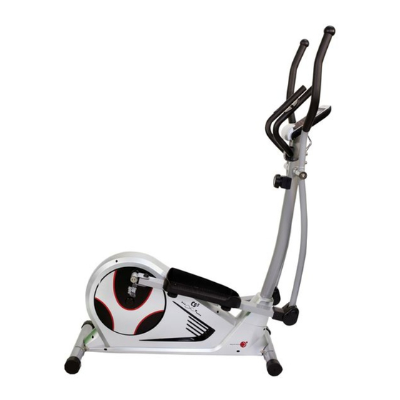
Christopeit Sport CS 5 Montage- Und Bedienungsanleitung

Heimsport-trainingsgerat
Vorschau ausblenden Andere Handbücher für CS 5:

Werbung

Verfügbare Sprachen
  • DE

Verfügbare Sprachen

  • DEUTSCH, seite 1
Montage- und Bedienungsanleitung u  r Bestell-Nr.
Assembly and exercise instructions or Order No.
Notice de montage et d'utilisation du
Montage- en bedieningshandleiding voor
Инструкция по монтажу и эксплуатации
Heimsport-Trainingsgera  t
CS 5
D
GB
F
No. de commande
NL
Bestellnummer
RU
№ заказа
99252 (B) -
99254 (B) -
99255 (B) -
99260 (B) -
1
(Weiß)
(Silber)
(Rot)
(Schwarz)

Werbung

loading

Inhaltszusammenfassung für Christopeit Sport CS 5

  • Seite 1 Heimsport-Trainingsgera  t CS 5 99252 (B) - (Weiß) Montage- und Bedienungsanleitung u  r Bestell-Nr. 99254 (B) - (Silber) Assembly and exercise instructions or Order No. 99255 (B) - (Rot) 99260 (B) - (Schwarz) Notice de montage et d’utilisation du No.
  • Seite 2 Inhaltsu  bersicht Contents Page 1. Wichtige Empehlungen und Sicherheitshinweise Seite 2. Einzelteileu  bersicht Seite 3. Stu  ckliste Seite 4. Montageanleitung mit Explosionsdarstellungen Seite - 10 Sommaire Page 5. Computeranleitung Seite 11 6. Trainingsanleitung Seite 12 Sehr geehrte Kundin, sehr geehrter Kunde Inhoudsopgave Pagina 31 Wir gratulieren Ihnen zum Kau...
  • Seite 5 Stu  ckliste - Ersatzteilliste CS 5 Stu  ckliste - Ersatzteilliste CS 5 Technische Daten: Stand: 01. 03. 2013 Art.-Nr. 99252 (B) - (Weiß) Art.-Nr. 99254 (B) - (Silber) Magnet-Brems-System ca. 8 kg Schwungmasse Art.-Nr. 99255 (B) - (Rot) Widerstandseinstellung 8-stug regelbar...
  • Seite 6 39-9861-VZ )* = Fu  r die Artikel CS 5 in weiß bitte die Ersatzteil Nr. -Endung „WS“ anstatt „SI“ nehmen und u  r den Artikel CS 5 in schwarz bitte die Ersatzteil Nr. -Endung „SW“ anstatt „SI“ nehmen.
  • Seite 7 Montageanleitung Bevor Sie mit der Montage beginnen, unbedingt unsere Empehlungen und Sicherheitshinweise beachten! Schritt 1: Montage des Vorderen Fußrohres (57) und des Hinteren Fußroh- res (31) am Grundrahmen (36) mittels der Schloßschrauben (30), der Unterlegscheiben 8//20 (9) und der Hutmuttern M8 (10). 1.
  • Seite 8 Schritt 3: Schritt 5: Montage der Grirohre (7) an den Verbindungsrohren (11) mittels der Montage der Fußschalenaunahme rechts (14R) und der Fußschalen- Schrauben (63) der Unterlegscheiben (9) und der Federringe (70). aunahme links (14L) incl. den Verbindungsrohren (11) an der Pedalkurbel (28) und dem Stu ...
  • Seite 9 Schritt 6: Montage der rechten Fußschale (18R) an der rechten Fußschalen- aunahme (14R) und der linken Fußschale (18L) an der linken Fußschalenaunahme (14L) mittels der Schlossschrauben (17), der Unterlegscheiben (24), Federringe (22) und der Sterngrimutter (23). 1. Die rechte Fußschale (18R) au die Fußschalenaunahme (14R) austecken. Die Bohrungen in den Teilen so ausrichten, dass sie u ...
  • Seite 10 Schritt 8: Kontrolle 1. Alle Verschraubungen und Steckverbindungen au ordnungsgema  ße Montage und Funktion pru  en. Die Montage ist hiermit beendet. 2. Wenn alles in Ordnung ist, mit leichten Widerstandseinstellungen mit dem Gera  t vertraut machen und die individuellen Einstellungen vornehmen. Anmerkung: Bitte das Werkzeug-Set und die Anleitung sorgsam aubewahren, da diese bei gg.
  • Seite 11 Computeranleitung fu  r CS 5 (Ho  chstgrenze der Anzeige 9990 Kalorien) 5. „PULS“-Anzeige: Es wird der aktuelle Puls in Schla  gen pro Minuten angezeigt. Eine Vorgabe bestimmter Werte mittels der „+“ und „-“ -Taste ist nicht mo  glich.
  • Seite 12 Garantiebestimmungen gema  ße Behandlung, Gewaltanwendung und Eingrien die ohne vorherige Absprache mit unserer Service Abteilung vorgenommen werden, erlischt die Garantie. Die Garantie beginnt mit dem Rechnungs- bzw. Auslieerdatum und betra  gt 24 Monate. Wa  hrend der Garantiezeit werden eventuelle Ma  ngel kostenlos Bitte bewahren Sie, alls mo ...
  • Seite 13 Contents 1. Summary o Parts Page 3 - 4 2. Important Recommendations and Saety Inormation Page 13 3. Parts List Page 14 - 15 4. Assembly Instructions With Exploded Diagrams Page 16 - 19 5. Computer instructions Page 20 6. Training Instructions Page 21 Dear customer, We congratulate you on your purchase o...
  • Seite 14 Parts List – Spare Parts List CS 5 Parts List – Spare Parts List CS 5 Technical data: Issue: 01. 03. 2013 Art.-Nr. 99252 (B) - (white) Art.-Nr. 99254 (B) - (silver) Magnetic brake system approx. 8 KG fywheel Art.-Nr. 99255 (B) - (red) 8-manually adjustable load steps Art.-Nr.
  • Seite 15 36-9211-28-BT Spring washer or M10 39-9995 M10x1 39-9820-SW 39-9861-VZ )* = For Article CS 5 white with white rame parts use “WS” instead o ”SI” and or CS 5 in black with black rame parts use “SW” instead o SI.
  • Seite 16 Assembly Instructions Beore beginning assembly, be sure to observe our recommendations and saety instructions. Step 1: Install o the ront ootbar (57) and the rear ootbar (31) on the main rame (36) with the carriage bolts (30), the washers 8//20 (9) and the cap nuts M8 (10).
  • Seite 17 Step 3: Step 5: Installation o the handgrip bars (7) on the connecting tubes (11) with Installation o the ootrest holder (14R) and the let ootrest holder (14L) bolt (63), washers (9) and (70). with the connecting tubes (11) to the pedal crank and the support (64) spring washer with the spring washers (70), the washers (49) and the screws (19).
  • Seite 18 Step 6: Installation o the right ootrest (18R) on the right ootrest holder (14R) and the let ootrest (18L) on the let ootrest holder (14R) with the carriage bolts (17), the washers (24), spring washer (22) and the handgrip nuts (23). 1.
  • Seite 19 Step 8: Checks 1. Check the correct installation and unction o all screwed and plug connections. Installation is thereby complete. 2. When everything is in order, amiliarise yoursel with the machine at a low resistance setting and make your individual adjustments. Note: Please keep the tool set and the instructions in a sae place as these may be required or repairs or spare parts orders becoming necessary later.
  • Seite 20 Computer instructions for CS 5 gently hold both metal parts each hand. With the good signals picked up by the computer, the heart mark in the HEART RATE Display shall fash. Sometimes the heart rate value is not useable, based on wet hands or any other contact problems during exercising.
  • Seite 21 Training instructions You must consider the ollowing actors in determining the amount o training eort required in order to attain tangible physical and health benets: 1. Intensity: The level o physical exertion in training must exceed the level o normal exertion without reaching the point o...
  • Seite 22 Sommaire 1. Aperçu des pie  ces Page 2. Recommandations importantes et re  gles de se  curite  Page 3. Nomenclature Page 23 - 24 4. Notice de montage avec e  corche  s Page 25 - 28 5.
  • Seite 23 Liste des pie  ces- CS 5 Liste des pie  ces - CS 5 Caracte  ristiques techniques : Version du : 01/ 03/ 2013 Ensemble composé d’un tapis roulant, d’un vélo de ftness et d’un Art.-Nr. 99252 (B) - (white) stepper, Enchaînement elliptique avant et arrière des mouvements...
  • Seite 24 39-9861-VZ )* = Pour les articles CS 5 dans blanc s‘il vous pla  t la pie  ce de rechange le nume  ro - la terminaison „WS“ au lieu de „SI“ et pour les articles CS 5 dans noir s‘il vous pla  t la pie  ce de rechange le nume  ro - la terminaison „SW“ au lieu de „SI“.
  • Seite 25 Instructions de montage Il est strictement conseille  d’observer nos recommandations et consignes de se  curite  avant de commencer le montage ! Etape n° 1: Montage du tube du pied avant (57) et du tube du pied arrie  re (31) sur le cadre de base (36) a ...
  • Seite 26 Etape n°3: Etape n° 5: Montage des manches (7) sur les tubes de communication (11) a  Montage du logement de la coque droite (14R) et du logement de la boulon brut a  te  te bombe  e et collet carre  (63), des rondelles (9) et des coque gauche (14L), tubes de jonction (11) y compris, sur la manivelle (70).
  • Seite 27 Etape n° 6: Montage de la coque de la pe  dale droite (18R) sur le logement de la coque de la pe  dale droite (14R) et de la coque de la pe  dale gauche (18L) sur le logement de la coque de la pe  dale gauche (14L) a  l’aide des boulons hexagonale a ...
  • Seite 28 Etape n° 8: Contro  le 1. Ve  rier si les assemblages et connexions ont e  te  eectue  s correctement et onctionnent. Le montage est maintenant termine  . 2. Si tout est en ordre, se amiliariser avec l’appareil en eectuant de le  gers re ...
  • Seite 29 Mode d’emploi de l‘ordinateur CS 5 Lorsqu‘une fe  che dirige  e vers le haut s’allume dans la ene  tre sur la partie late  rale, il est pos- sible d’entrer une limite supe  rieure de pouls. En re  appuyant sur la touche „F“, une fe ...
  • Seite 30 Recommandations pour l’entra  nement Les acteurs ci-apre  s doivent e  tre pris en compte pour la de  termination de l’entra  nement indispensable an d’ame  liorer concre  tement son physique et sa sante  : 1.
  • Seite 31 Inhoudsopgave 1. Overzicht van de losse delen pagina 3 - 4 2. Belangrijke aanbevelingen en veiligheidsinstructies pagina 31 3. Stuklijst pagina 32 - 33 4. Montagehandleiding met explosietekeningen pagina 34 - 37 5. Handleiding bij de computer pagina 38 6. Trainingshandleiding pagina 39 Geachte klant Wij willen u van harte gelukwensen met de aanscha...
  • Seite 32 Stuklijst - reserveonderdelenlijst CS 5 Stuklijst - reserveonderdelenlijst CS 5 Technische specifcatie: Stand: 01. 03. 2013 Art.-Nr. 99252 (B) - (white) Magnetisch remsysteem Art.-Nr. 99254 (B) - (silver) ca. 8 kg vliegwielmassa 8-traps vergrendeling Art.-Nr. 99255 (B) - (red) handpolsslag meting loopvlak 3-voudig verstelbaar Art.-Nr.
  • Seite 33 M10 39-9995 Asmoer M10x1 39-9820-SW Asmoer 39-9861-VZ )* = Het CS 5 objecten in wit gelieve reserveonderdelen de No-ending ‚WS‘ in plaats van „SI“ en het CS 5 objecten in zwart gelieve reserveonderdelen de No-ending ‚SW‘ in plaats van „SI“.
  • Seite 34 Montagehandleiding Voordat u met de montage begint, absoluut onze adviezen en veiligheidsvoorschriten in acht nemen! Stap 1: Montage van de voorste voetbuis (57) en de achterste voetbuis (31) op het frame (36) door middel van de sluitschroeven (30), de onderlegplaatjes 8//20 (9)en de dopmoeren M8 (10). 1.
  • Seite 35 Stap 3: Stap 5: Montage van de greepbuizen (7) aan de verbindingsbuizen (11) met Montage van de voetschaalbevestiging rechts (14R) en de behulp van de slotschroe (63), onderlegplatje (9) en de veerring (70). voetschaalbevestiging links (14L) incl. de verbindingsbuizen (11) op de pedaalkcrank (28) en de steunbuis (64) met de veerring (70), de 1.
  • Seite 36 Stap 6: Montage van de rechter voetschaal (18R) aan de rechter voetschaalbevestiging (14R) en de linker voetschaal (18L) aan de linker voetschaalbevestiging (14L) met behulp van de slotschroe (17), de onderlegplatje (24), veerring (22) en de stergreepmoer (23). 1. De rechter voetschaal (18R) op de bevestiging (14R) steken. De openingen in de delen zo uitlijnen dat ze precies boven elkaar liggen.
  • Seite 37 Stap 8: Controle: 1. Alle schroe- en stekkerverbindingen op een correcte montage en juiste werking controleren. Daarmee is de montage bee  indigd. 2. Wanneer alles in orde is, met lichte weerstandsinstellingen vertrouwd raken met het apparaat en de individuele instellingen vastzetten. Opmerking: De gereedschapsset en de gebruiksaanwijzing a.u.b.
  • Seite 38 Computerhandleiding voor CS 5 5. „PULS“-weergave: De actuele hartslag wordt in slagen per minuut weergegeven. Een bepaalde waarde kan niet worden ingesteld met behulp van de „+“ en „-“-toets. Als er een bovengrens van de hartslag is ingevoerd wordt wanneer deze wordt overschreden komt een signaal weergegeven.
  • Seite 39 Trainingshandleiding De onderstaande actoren moeten in acht worden genomen bij het bepalen van de benodigde training voor het bereiken van een merkbare verbetering van uw guur en gezondheid: 1. Intensiteit: De mate van lichamelijke belasting bij de training moet de normale belasting overschrijden, zonder dat u daarbij buiten adem en/o...
  • Seite 40 Обзор содержания Важные рекомендации и указания по безопасности ctp. 2. Обзор отдельных деталей стр. 3. Спецификация стр. 41 - 42 4. Руководство по сборке с отдельными иллюстрациями стр. 43 - 46 5. Руководство по использованию компьютера стр. 6. Руководство по тренировкам стр.
  • Seite 41 Спецификация - Список запасных частей CS5 Спецификация - Список запасных частей CS5 Технические характеристики По состоянию на 01.03.2013 Art.-Nr. 99252 (B) - (white) Art.-Nr. 99254 (B) - (silver) Магнитная система нагружения Иннерционная масса 8 кг Art.-Nr. 99255 (B) - (red) 8 уровней...
  • Seite 42 39-9995 Осевая гайка M10x1 39-9820-SW Осевая гайка 39-9861-VZ )* = Для статей CS 5 в бело, пожалуйста, запасную часть номер окончание „WS“ вместо „SI“ и Для статей CS 5 в черно, пожалуйста, запасную часть номер окончание „SW“ вместо „SI“ .
  • Seite 43 Спецификация Прежде чем Вы начнете производить монтаж, следует непременно обратить внимание на наши рекомендации и указания по технике безопасности Шаг 1: Монтаж передней ножной трубы (57) и задней ножной трубы (31) на Основную раму (36) с помощью замкового болта с грибовидной головкой...
  • Seite 44 Шаг 3: Шаг 5: Монтаж рукояток (7) на соединительную трубу (11) с помощью Монтаж правого ножного рычага (14R) и левого ножного рычага болтов (63), подкладных шайб (9) и Пружинная шайба (70). (14L) с соединительной трубой (11) на шатун педали (28) и на 1.
  • Seite 45 Шаг 6: Монтаж правого фиксатора стопы (18R) на правый ножной рычаг (14R) и левого фиксатора стопы (18L) на левый ножной рычаг (14L) с помощью замкового болта (17), подкладных шайб (31), пружинных шайб (22), грибковых гаек (24). 1. Вставьте правый фиксатор стопы (18R) на правый ножной рычаг (14R) таким...
  • Seite 46 Шаг 8: Контроль 1. Проверьте все соединения на правильность сборки и проведите проверку функциональности. При этом монтаж считается законченым. 2. Если все в порядке, проведите пробную тренировку при маленькой нагрузке, и индивидуально настройте тренажер. Замечание: Пожалуйста, сохраняйте набор инструментов для последующих возможных...
  • Seite 47 Руководство по использованию компьютера на тренажере 4. Функция „КМ“ (Километраж): Показывается количество пройденных километров. Можно предварительно задать определенный показатель в этой функции с помощью кнопки „+“ + „-“ . Если Вы задали определенный показатель, то указывается количество оставшихся до заданного предела километров. Как...
  • Seite 48 ИНСТРУКЦИЯ ПО ТРЕНИРОВКЕ Вы должны учитывать следующие факторы, чтобы определить Мотивация верные параметры тренировок для достижения ощутимых физических Ключевым моментом успеха программы являются регулярные результатов и пользы для здоровья. тренировки. Вам следует установить конкретное время и место на каждый день для тренировок и внутренне подготовить себя к ним. Интенсивность...

Diese Anleitung auch für:

Cs 5 silber99254c99252b99254b99255b99260b ... Alle anzeigen