DICHIARAZIONE DI CONFORMITÀ CE (ES) DECLARACIÓN DE CONFORMIDAD CE Noi, DAB Pumps S.p.A. - Via M.Polo, 14 – Mestrino (PD) – Nosotros, DAB Pumps S.p.A. - Via M.Polo, 14 – Mestrino Italy, dichiariamo sotto la nostra esclusiva responsabilità che (PD) –...
Seite 3
ITALIANO pag. FRANÇAIS page 13 ENGLISH page 22 DEUTSCH Seite 31 NEDERLANDS bladz. 40 ESPAÑOL pág. РУССКИЙ стр.
Seite 4
Generalmente l’impianto è circoscritto a impianto di irrigazione, lavabiancheria, cassetta di scarico WC, lava pavimenti . Lo scopo principale del sistema ACTIVE SWITCH è di dare priorità al consumo dell’acqua piovana all’acqua di rete. Quando l’acqua piovana contenuta nel serbatoio di raccolta è insufficiente, l’unità di controllo passa all’alimentazione idrica di rete, assicurando cosi un afflusso di acqua ai punti di...
Seite 5
ITALIANO acqua piovana e il serbatoio dell’acqua di rete integrato nel sistema viene selezionato mediante valvola a tre vie istallata all’aspirazione della pompa. Il funzionamento della pompa è esattamente quello di una pompa con sistema “start-stop” con controllo di flusso e di pressione,. Al calare della pressione al di sotto di un valore prestabilito la pompa si avvia, alla chiusura del rubinetto la pompa si arresta.
Seite 6
ITALIANO 3. Dati tecnici EUROINOX 30/50 50Hz Portata (lt/min-m3/h) max 80-4,8 Prevalenza Hm max 42,2 Temperatura del liquido pompato Da +5°C a +35°C Pressione massima del sistema Max 6 bar Pressione massima rete Max 4 bar Portata minima rete Min 10 lt/min Altezza massima del punto di utilizzo più...
Seite 7
ITALIANO Dati tecnici JETCOM 102 60Hz Portata (lt/min-m3/h) max 60-3,6 Prevalenza Hm max 53,8 Temperatura del liquido pompato Da +5°C a +35°C Pressione massima del sistema Max 6 bar Pressione massima rete Max 4 bar Portata minima rete Min 10 lt/min Altezza massima del punto di utilizzo più...
4.1. Montaggio a parete Prima dell’installazione, verificare che l’impianto fognario sia almeno 1-2 metri più basso del punto di installazione dell’ACTIVE SWITCH (normalmente si considera il livello fognario il piano stradale). Il locale deve avere uno scarico collegato al sistema fognario.
Seite 9
ITALIANO Se la pendenza del tubo di scarico risultasse insufficiente, installare una stazione di sollevamento al fine di garantirne lo smaltimento. 4.3. Collegamento del tubo dell’acqua di rete Procedere come segue: Collegare il tubo di alimentazione acqua di rete alla filettatura da 3/4”uscente dal lato destro del serbatoio ( vedi fig.
ITALIANO Tabella 1 Corrispondenza tra lunghezza ed altezza del tubo di aspirazione Procedere come segue: 1. Collegare il tubo di aspirazione al raccordo indicato in figura 01 punto 3. ATTENZIONE Utilizzando il flessibile in dotazione, il tubo di aspirazione può essere ruotato in un arco di 180°. Utilizzare la tabella 1 per calcolare la massima lunghezza del tubo di aspirazione.
Seite 11
ITALIANO Figura 04 Interruttore a galleggiante Tubo di aspirazione Fondo del serbatoio Dopo aver installato il galleggiante, assicurare e proteggere il cavo lungo il percorso stabilito. L’interruttore a galleggiante deve commutare il contatto almeno 15 cm prima che la valvola di fondo (valvola di aspirazione della pompa) prenda aria.
Seite 12
ITALIANO 6. Pannello di controllo pompa Descrizione pannello di controllo. Led verde pompa ON. Led rosso pompa in allarme. 7. Manutenzione Il sistema non necessita di manutenzione periodica. ATTENZIONE Prima di accedere all’unità, scollegare la spina elettrica dalla presa, e chiudere le valvole idrauliche di intercettazione, assicurarsi che nessuno possa reinserire la presa o aprire le valvole durante l’ispezione.
2. Description générale du système L’unité ACTIVE SWITCH sert à la gestion et à la distribution de l’eau de pluie. L’unité détecte le manque d’eau dans le système collecteur, tant de l’eau de pluie que de l’eau de ville, et apporte les corrections nécessaires pour garantir le fonctionnement correct de l’installation (afin d’assurer en...
Seite 14
FRANÇAIS collecteur est insuffisante, l’unité de contrôle passe à l’alimentation en eau de ville, en assurant ainsi l’arrivée d’eau aux points de puisage.(N.B. L’eau fournie par le système n’est pas potable). Le raccordement entre le réservoir collecteur d’eau de pluie et le réservoir d’eau de ville intégré au système est sélectionné...
FRANÇAIS 3. Données techniques EUROINOX 30/50 50Hz Débit (l/min-m³/h) max. 80-4,8 Hauteur d’élévation Hm max. 42,2 Température du liquide pompé de +5°C à +35°C Pression maximum du système Max. 6 bar Pression maximum service d’eau Max. 4 bar Débit minimum service d’eau Min.
Seite 16
FRANÇAIS Données techniques JETCOM 102 60Hz Débit (l/min-m³/h) max. 60-3,6 Hauteur d’élévation Hm max. 53,8 Température du liquide pompé de +5°C à +35°C Pression maximum du système Max. 6 bar Pression maximum service d’eau Max. 4 bar Débit minimum service d’eau Min.
Avant l’installation, vérifier que la conduite d’égout se trouve au moins 1-2 mètres plus bas que le point d’installation du ACTIVE SWITCH (normalement on considère que le niveau de la conduite d’égout correspond au niveau de la chaussée). ...
Seite 18
FRANÇAIS Raccorder le tuyau à l’égout. Si la pente du tuyau d’évacuation se révèle insuffisante, installer une station de relevage afin d’en garantir l’évacuation. 4.3 Raccordement du tuyau de l’eau de ville Procéder comme suit: Raccorder le tuyau d’alimentation en eau de ville au filetage 3/4” sortant du côté droit du réservoir (voir fig.
Seite 19
FRANÇAIS Tableau 1 Correspondance entre longueur et hauteur du tuyau d’aspiration Procéder comme suit: Raccorder le tuyau d’aspiration au raccord indiqué sur la figure 01 point 3. ATTENTION En utilisant le tuyau flexible fourni, le tuyau d’aspiration peut être tourné sur un arc de 180°. Utiliser le tableau 1 pour calculer la longueur maximum du tuyau d’aspiration.
FRANÇAIS Figure 04 Interrupteur à flotteur Tuyau d’aspiration Fond du réservoir Après avoir installé le flotteur, fixer solidement le câble et le protéger sur tout son parcours. L’interrupteur à flotteur doit commuter le contact au moins 15 cm avant que le clapet de pied (clapet d’aspiration de la pompe) aspire de l’air.
FRANÇAIS 6. Panneau de commande pompe Description panneau de commande. 1. Led verte pompe ON. 2. Led rouge pompe en alarme. 7. Maintenance Le système n’a pas besoin de maintenance périodique. ATTENTION Avant d’accéder aux parties internes ou externes reliées à l’unité, débrancher la fiche électrique de la prise et fermer les vannes hydrauliques d’isolement, s’assurer que personne ne peut rebrancher la fiche ou ouvrir les vannes durant l’inspection.
Seite 22
WC flushing tank and floor cleaner systems. The main objective of the ACTIVE SWITCH system is to give priority to the use of rain water over that of the mains water. When the rain water contained in the collection tank is insufficient, the control unit passes to the mains water supply thereby ensuring a flow of water at the extraction points (The water supplied by the is not drinkable).
Seite 23
ENGLISH The pump operates exactly the same as a pump with a “start-stop” system and flow and pressure control. When the pressure drops below the set value the pump starts, when the tap is turned off the pump stops, if there is a lack of water the pump stops and a warning is signalled on the pump’s control panel.
Seite 24
ENGLISH 3. Technical specifications EUROINOX 30/50 50Hz Flow rate (l/min-m3/h) max 80-4,8 Head Hm max 42,2 Pumped liquid temperature From +5°C to +35°C Maximum system pressure Max 6 bar Maximum mains pressure Max 4 bar Minimum mains flow rate Min 10 lt/min Maximum usage height 15 m Power supply 1 phase...
Seite 25
ENGLISH Technical specifications JETCOM 102 60Hz Flow rate (l/min-m3/h) max 60-3,6 Head Hm max 53,8 Pumped liquid temperature From +5°C to +35°C Maximum system pressure Max 6 bar Maximum mains pressure Max 4 bar Minimum mains flow rate Min 10 lt/min Maximum usage height 15 m Power supply 1 phase...
4.1 Wall assembly Before installation, make sure that the sewerage system is at least 1-2 meters below the point in which the ACTIVE SWITCH is to be installed (the road level is normally taken as the sewerage level). ...
Seite 27
ENGLISH Connect the discharge to the sewerage system. If the incline of the discharge pipe is insufficient, install a lifting station in order to guarantee the discharge. 4.3 Mains water pipe connection Proceed as follows: Connect the mains water supply pipe to the 3/4” threaded outlet on the righthand side of the tank (see fig.
Seite 28
ENGLISH Table 1 Correspondence between the length and height of the suction pipe Proceed as follows: 1. Connect the suction pipe to the connector as indicated in figure 01 point 3. WARNING By using the supplied hose the suction pipe can be bent through 180°. Use table 1 to calculate the maximum length of the suction pipe.
Seite 29
ENGLISH Figure 04 Float switch Suction pipe Bottom of the tank After having fitted the float make sure that the cable is protected and made safe along its entire length. The float switch must change the contact at least 15 cm before the foot valve (pump suction valve) takes in air.
Seite 30
ENGLISH 6. Pump control panel Control panel description. pump ON green LED pump in alarm red LED 7. Maintenance The system does not require periodic maintenance. WARNING Before touching the unit, disconnect the plug from the mains socket, make sure that the on-off valves are closed and that no one can reconnect the power supply or open the valves during inspection.
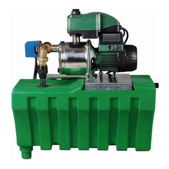
Für Zubehör gelten die üblichen Angaben. 2. Allgemeine Beschreibung des Systems Die Einheit ACTIVE SWITCH dient zur Verwaltung und Verteilung von Regenwasser. Die Einheit nimmt den Wassermangel im Sammelsystem sowohl von Regenwasser als auch des Wassernetzes wahr und führt die Berichtigungen aus, um den korrekten Betrieb der Anlage zu gewährleisten (bzw.
Seite 32
DEUTSCH Trinkwasser). Die Verbindung zwischen Regen- und Leitungswasserspeicher in der Anlage erfolgt mittels Dreiwege-Ventil, das in der Ansaugung der Pumpe installiert ist. Die Pumpe funktioniert wie eine Pumpe mit „Start/Stopp“-System mit Kontrolle des Wasserflusses und des Drucks. Die Pumpe startet, wenn der Druck unter einen bestimmten Wert sinkt; beim Schließen des Hahns hält die Pumpe an.
Seite 33
DEUTSCH 3. Technische Daten EUROINOX 30/50 50Hz Wasserfluss (l/Min. - m3/h) max. 80-4,8 Förderhöhe Hm max. 42,2 Temperatur der gepumpten Flüssigkeit von +5°C bis +35°C Höchstdruck der Anlage max. 6 bar Höchstdruck des Netzes max. 4 bar Minimaler Leitungswasserfluss min. 10 l/Min. Max.
DEUTSCH Technische Daten JETCOM 102 60Hz Wasserfluss (l/Min. - m3/h) max. 60-3,6 Förderhöhe Hm max. 53,8 Temperatur der gepumpten Flüssigkeit von +5°C bis +35°C Höchstdruck der Anlage max. 6 bar Höchstdruck des Netzes max. 4 bar Minimaler Leitungswasserfluss min. 10 l/Min. Max.
Den Bügel an der Wand befestigen und seine Waagerechte überprüfen. Prüfen, dass Bügel und Wand fest miteinander vereint sind. Die Einheit ACTIVE SWITCH wie in der Abbildung gezeigt anbringen. Die Sicherheitsschrauben befestigen - siehe Abb. 02 und 02A. Die 4 mitgelieferten Schwingungsdämpfer zwischen Bügel und Wand (2 Schwingungsdämpfer) und zwischen Tank und Wand (2 Schwingungsdämpfer) einlegen, um die Übertragung von...
DEUTSCH Den Abfluss mit der Kanalisation verbinden. Sollte die Neigung des Abflussrohrs ungenügend sein, muss ein Fördersystem installiert werden. 4.3 Verbindung des Leitungswasserrohrs Wie hier folgend angegeben vorgehen: Die Leitungswasserzuleitung mit dem 3/4“ Gewinde, das an der rechten Speicherseite austritt, verbinden (siehe Abb.
Seite 37
DEUTSCH Tabelle 1 Übereinstimmung zwischen Länge und Höhe des Ansaugrohrs Wie hier folgend angegeben vorgehen: das Ansaugrohr mit dem in Abb. 01 Punkt 3 gezeigten Anschluss verbinden. ACHTUNG Wenn die mitgelieferte Schlauchleitung benutzt wird, kann das Ansaugrohr bis 180° gedreht werden. Die Höchstlänge des Ansaugrohrs mit Hilfe von Tabelle 1 berechnen.
DEUTSCH Abbildung 04 Schwimmerschalter Saugrohr Speicherboden Das Kabel nach der Installation des Schwimmers auf seiner Strecke sichern und schützen. Der Schwimmerschalter muss den Kontakt mindestens15 cm bevor das Bodenventil (Saugventil der Pumpe) Luft ansaugt, umschalten. ACHTUNG SICHER STELLEN, DASS DAS SYSTEM FEST MIT DER MAUER VERANKERT IST. 5.
DEUTSCH 6. Steuerpult der Pumpe Beschreibung des Steuerpults. Grüne LED Pumpe EIN. Rote LED Pumpe in Alarm. 7. Wartung Das System bedarf keiner periodischen Wartung. ACHTUNG Vor dem Zugriff auf die Einheit muss der Stecker aus der Steckdose gezogen werden. Absperrventile schließen und sicherstellen, dass der Stecker oder die Ventile während der Überprüfung nicht unbeabsichtigt eingeschaltet werden können.
Seite 40
2. Algemene beschrijving van het systeem Het ACTIVE SWITCH-systeem dient voor het beheer en distributie van het regenwater. Het systeem constateert eventueel dat er geen water in het opvangsysteem van zowel het regenwater als het leidingwater is en brengt de nodige correcties aan om u ervan te verzekeren dat de installatie correct werkt (ofwel zorgt ervoor dat de vastgestelde tappunten nooit zonder water zijn).
Seite 41
Het voornaamste doel van het ACTIVE SWITCH-systeem is het verbruik van regenwater te bevoordelen boven dat van water uit de waterleiding. Wanneer het regenwater in het opvangreservoir onvoldoende is, gaat de besturingseenheid over op watertoevoer uit de waterleiding, waardoor toevoer van water naar de tappunten zekergesteld wordt (N.B.
Seite 42
NEDERLANDS 3. Technische gegevens EUROINOX 30/50 50Hz Max wateropbrengst (l/min-m3/h) 80-4,8 Max opvoerhoogte Hm 42,2 Temperatuur van de verpompte vloeistof van +5°C tot +35°C Maximumdruk van het systeem Max 6 bar Maximumdruk van de waterleiding Max 4 bar Minimumwateropbrengst waterleiding Min 10 l/min Maximumhoogte van het hoogste tappunt 15 m...
Seite 43
NEDERLANDS Technische gegevens JETCOM 102 60Hz Max wateropbrengst (l/min-m3/h) 60-3,6 Max opvoerhoogte Hm 53,8 Temperatuur van de verpompte vloeistof van +5°C tot +35°C Maximumdruk van het systeem Max 6 bar Maximumdruk van de waterleiding Max 4 bar Minimumwateropbrengst waterleiding Min 10 l/min Maximumhoogte van het hoogste tappunt 15 m Spanning stroomvoorziening 1 fase...
Controleer voor installatie dat het rioolstelsel ten minste 1-2 meter beneden het punt ligt waarop de ACTIVE SWITCH is geïnstalleerd ( gewoonlijk wordt het straatniveau als rioolpeil aangemerkt). De ruimte moet een afvoer hebben die op het riool is aangesloten.
Seite 45
NEDERLANDS Als de helling van de afvoerbuis onvoldoende mocht blijken te zijn, dient u een opvoerstation te installeren om de verwerking van de afvoer zeker te stellen 4.3 Aansluiting van de buis voor het water uit de waterleiding Ga als volgt te werk: Sluit de buis voor toevoer van water uit de waterleiding op de schroefdraad van 3/4”...
Seite 46
NEDERLANDS Tabel 1 Overeenstemming tussen de lengte en hoogte van de aanzuigleiding Ga als volgt te werk: 1. Sluit de aanzuigleiding op het koppelstuk aan zoals dat op afbeelding 01 punt 3 is aangegeven. LET OP Gebruik de meegeleverde slang, de aanzuigleiding kan over een afstand van 180° gedraaid worden. Gebruik tabel 1 om de maximumlengte van de aanzuigleiding te berekenen.
Seite 47
NEDERLANDS Afbeelding 04 Vlotterschakelaar Zuigleiding Bodem van het reservoir Nadat u de vlotter geïnstalleerd hebt, dient u de kabel over het vastgestelde traject vast te zetten en te beschermen. De vlotterschakelaar moet het contact tenminste 15 cm voordat de voetklep (zuigklep van de pomp) lucht aanzuigt omschakelen.
Seite 48
NEDERLANDS 6. Bedieningspaneel pomp Beschrijving van het bedieningspaneel. Groen lampje pomp ON Rood lampje pomp in alarm 7. Onderhoud Het systeem behoeft geen enkel periodiek onderhoud. LET OP Voordat u werkzaamheden op het systeem gaat uitvoeren dient u de stekker uit het stopcontact te halen, de afsluitkleppen dicht te doen en te controleren dat niemand tijdens de werkzaamheden de stekker weer in het stopcontact kan stoppen of de kleppen kan openen ...
Seite 49
WC, fregasuelos. La función principal del sistema ACTIVE SWITCH es la de dar la prioridad al consumo de agua de lluvia sobre aquel de agua de red. Cuando el agua de lluvia contenida en el depósito de recogida es...
Seite 50
ESPAÑOL agua en los puntos de utilización (N.B. El agua suministrada por el sistema no es potable). La conexión entre el depósito de recogida del agua de lluvia y el depósito del agua de red integrado en el sistema se selecciona mediante la válvula de tres vías instalada en la aspiración de la bomba. El funcionamiento de la bomba es exactamente aquel de una bomba con sistema “start-stop”...
Seite 51
ESPAÑOL 3. Datos técnicos EUROINOX 30/50 50Hz Caudal (l/min-m3/h) máx. 80-4,8 Altura de elevación Hm máx. 42,2 Temperatura del líquido bombeado De +5°C a +35°C Presión máxima del sistema Máx. 6 bares Presión máxima de red Máx. 4 bares Caudal mínimo de red Mín.
Seite 52
ESPAÑOL Datos técnicos JETCOM 102 60Hz Caudal (l/min-m3/h) máx. 60-3,6 Altura de elevación Hm máx. 53,8 Temperatura del líquido bombeado De +5°C a +35°C Presión máxima del sistema Máx. 6 bares Presión máxima de red Máx. 4 bares Caudal mínimo de red Mín.
4.1 Montaje en la pared Antes de la instalación, controle que la instalación cloacal esté 1-2 metros más abajo del punto de instalación del ACTIVE SWITCH (normalmente el nivel cloacal se considera el plano de la calle). El local debe tener una descarga conectada al sistema cloacal.
Seite 54
ESPAÑOL Conecte la descarga al sistema cloacal. Si la pendiente del tubo de descarga fuera insuficiente, instale una estación de elevación para garantizar la eliminación. 4.3 Conexión del tubo de agua de red Proceda de la siguiente manera: Conecte el tubo de alimentación del agua de red a la rosca de 3/4” de salida del lado derecho del depósito (véase la fig.
Seite 55
ESPAÑOL Tabla 1 Correspondencia entre la longitud y la altura del tubo de aspiración Proceda de la siguiente manera: Conecte el tubo de aspiración al racor indicado en la figura 01 punto 3. ATENCIÓN Utilizando el tubo flexible suministrado, el tubo de aspiración puede girarse en un arco de 180°. Utilice la tabla 1 para calcular la longitud máxima del tubo de aspiración.
Seite 56
ESPAÑOL Figura 04 Interruptor de flotador Tubo de aspiración Fondo del depósito Después de haber instalado el flotador, controle el cable y protéjalo en todo su recorrido. El interruptor de flotador debe conmutar el contacto por lo menos 15 cm antes de que la válvula de fondo (válvula de aspiración de la bomba) aspire aire.
Seite 57
ESPAÑOL 6. Panel de control de la bomba Descripción del panel de control. Led verde bomba ON. Led rojo bomba en alarma. 7. Mantenimiento El sistema no requiere mantenimientos periódicos. ATENCIÓN Antes de acceder a la unidad, desconecte el enchufe del toma de corriente y cierre las válvulas hidráulicas de interceptación;...
Seite 58
для принадлежностей действительны те же указания 2. Общее описание системы Блок ACTIVE SWITCH служит для управления и распределения дождевой воды. Блок определяет отсутствие воды в системе сбора, как дождевой, так и водопроводной воды, и вносит корректировки для правильной работы установки (то есть чтобы указанные системы...
Seite 59
РУССКИЙ из водопровода, гарантируя таким образом приток воды в точки ее взятия (ПРИМ. Вода, снабжаемая системой, не питьевая). Соединение между резервуаром сбора дождевой воды и резервуаром воды сети, встроенной в систему, выбирается при помощи трехходового клапана, установленного на всасывании насоса. Работа...
Seite 60
РУССКИЙ 3. Технические характеристики EUROINOX 30/50 50Hz Поток (л/мин-м3/час) макс 80-4,8 Напор Hm макс 42,2 Температура перекачиваемой жидкости от +5°C до +35°C Максимальное давление системы Макс 6 бар Максимальное давление сети Макс 4 бар Минимальный поток сети Мин 10 л/мин Максимальная...
Seite 61
РУССКИЙ Технические характеристики JETCOM 102 60Hz Поток (л/мин-м3/час) макс 60-3,6 Напор Hm макс 53,8 Температура перекачиваемой жидкости от +5°C до +35°C Максимальное давление системы Макс 6 бар Максимальное давление сети Макс 4 бар Минимальный поток сети Мин 10 л/мин Максимальная высота наиболее высокой 15 м...
должен быть расчитан в зависимости от объема воды, подаваемого из водопроводной сети. 4.1 Монтаж на стену Перед установкой, проверить, что канализационная система находится минимум на 1-2 метра ниже, чем точка установки ACTIVE SWITCH (обычно уровнем канализационной системы считается уровень грунта). Помещение должно иметь слив, соединенный с канализационной системой.
Seite 63
РУССКИЙ если наклон трубы слива оказывается недостаточным, установить станцию подъема, для обеспечения оттока. 4.3 Соединение трубы воды из водопроводной сети Действовать, как указано далее: соединить трубу подачи воды из водопроводной сети с резьбой 3/4”, выходящей с правой стороны резервуара ( смотри рис. 01 пункт 8). проверить, что...
Seite 64
РУССКИЙ Таблица 1 Соотношение между длиной и высотой трубы всасывания Действовать, как указано далее: соединить трубу всасывания с патрубком, показанным на рисунке 01 пункт 3. ВНИМАНИЕ Используя шланг в комплекте, можно повернуть трубу всасывания по дуге 180°. Использовать таблицу 1 для расчета максимальной длины трубы всасывания. 4.5 Соединение...
Seite 65
РУССКИЙ Рисунок 04 Πоплавковый выключатель Вытяжная труба Дно резервуара После того, как поплавок установлен, закрепить и защитить кабель вдоль пути прокладки. Поплавковый выключатель должен переключать контакт не менее чем за 15 см до того, как донный клапан (всасывающий клапан насоса) всосет воздух. ВНИМАНИЕ...
Seite 66
РУССКИЙ 6. Панель управления насосом Описание панели управления. Зеленый светодиод насос ВКЛ. Красный светодиод насос в состоянии тревоги 7. Техобслуживание Система не нуждается в периодическом техобслуживании. ВНИМАНИЕ Перед тем, как получить доступ к блоку, вынуть электрическую вилку из розетки, и закрыть отсечные...
Seite 68
D - 47918 Tönisvorst - Germany Tel. +32 2 4668353 Tel. +49 2151 82136-0 Fax +32 2 4669218 Fax +49 2151 82136-36 PUMPS AMERICA, INC. DAB PUMPS DIVISION DAB PUMPS IBERICA S.L. 3226 Benchmark Drive Parque Empresarial San Fernando Ladson, SC 29456 USA Edificio Italia Planta 1ª...