Herunterladen Inhalt Inhalt Diese Seite drucken
GEZE RSZ 6 Montageanleitung
Vorschau ausblenden Andere Handbücher für RSZ 6:

Werbung

Verfügbare Sprachen

Verfügbare Sprachen

GEZE
RSZ 6
DE
Rauchschalterzentrale
GB
Smoke switch control unit
FR
Centrale de détection de fumée
DE
Montageanleitung
GB
Installation instructions
FR
Instruction de montage
1

Werbung

Inhaltsverzeichnis
loading

Inhaltszusammenfassung für GEZE RSZ 6

  • Seite 1 GEZE Montageanleitung Installation instructions RSZ 6 Instruction de montage Rauchschalterzentrale Smoke switch control unit Centrale de détection de fumée...
  • Seite 2: Zu Diesem Dokument

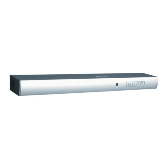
    Zu diesem Dokument RSZ 6 Zu diesem Dokument Diese Anleitung beschreibt die Montage und den Anschluss sowie die Inbetriebnahme der GEZE RSZ 6 Rauch- schalterzentrale. Produktbeschreibung Diese Rauchschalterzentrale löst im Brandfall oder bei Netzausfall die elektrische Feststellung aus und die Tür schließt selbsttätig.
  • Seite 3: Lieferumfang

    Zubehörbeutel (ohne Abbildung) Rauchschalter (verpackt) Montage, Befestigung 6. 1 Montageposition festlegen Abb.: 6.1.1 Lichte Öffnungshöhe Montagebereich RSZ 6 Lichte Öffnungsbreite Bohrbild RSZ 6 Abb.: 6.2.1 M5, Befestigungslöcher Ø 15 mm, Öffnung für Zusatzanschlüsse Ø 15 mm, Stromzuführung 230 V AC...
  • Seite 4: Rauchschalterzentrale Befestigen Und Netzanschluss

    WICHTIG Um ein einwandfreies Ansprechen des Rauchschalters zu gewährleisten, darf eine Distanz zwischen Oberkante RSZ 6 und Decke/Sturz von mindestens 10 mm nicht unterschritten werden! Der Rauchmelder darf ausschließlich über der Türöffnung an der senkrechten Wand montiert werden. Montage- bereich beachten (Abb.: 6.1.1) Je nach Feststellanlage beachten Sie bitte auch das Dokument „Anleitung zur Montage, Inbetriebnahme, Bedie-...
  • Seite 5 RSZ 6 Montage, Befestigung Abb.: 6.2.2 230 V Netzkabel auf ca. 80 mm ablängen (1.). 230 V Netzkabel zur Klemme verlegen und anschließen (2.). Deckel des Anschlussgehäuses schließen und verschrauben (3.). Blende montieren (6.5) Abb.: 6.3.1 VORSICHT! Kabel nicht quetschen.
  • Seite 6: Blende Entfernen

    Einbau und Anschluss des Rauchschalters Abb.: 7.2.1 Rauchschalter einklipsen. Abb.: 7.2.2 Kabel 24 V des Netzteils (1.) einstecken. Zusatzanschlüsse siehe separates Dokument „Anleitung zur Montage, Inbetriebnahme, Bedienung und Wartung der GEZE Feststellanlage FA GC“. Blende einklipsen (2.) VORSICHT! Kabel nicht quetschen. DE 6...
  • Seite 7: Ersteinschaltung, Test

    Nach dem betriebsfertigen Einbau der Anlage ist am Verwendungsort deren einwandfreie Funktion und vor- schriftsmäßige Installation durch eine Abnahmeprüfung festzustellen. Abnahmeprüfung durch autorisiertes Fachpersonal siehe Dokument „Anleitung zur Montage, Inbetriebnahme, Bedienung und Wartung der GEZE Feststellanlage FA GC“. Wartung, Pflege, Reparatur Die Einbaufirma muss den Betreiber der Anlage auf diesen Teil der Montageanleitung aufmerksam machen, und diese sowie die Benutzerinformation (Beipackzettel zum Türschließer) dem Betreiber aushändigen.
  • Seite 8: About This Document

    RSZ 6 About this document These instructions describe the installation and commissioning of the GEZE TS RSZ 6 smoke switch control unit. Product description In case of fire or power failure, the smoke switch unit activates the electrical hold-open device and the door closes automatically.
  • Seite 9: Scope Of Delivery

    Smoke switch (packed) Mounting and securing 6. 1 Determine mounting position Fig.: 6.1.1 Clear opening height Mounting position RSZ 6 Clear opening width Drilling pattern RSZ 6 Fig.: 6.2.1 M5, fixing holes Ø 15 mm, opening for additional connections Ø 15 mm, power supply 230 V AC...
  • Seite 10 Make opening for additional connections (C). IMPORTANT: To guarantee correct functioning of the smoke switch, GEZE recommends that the distance between the upper edge RSZ 6 and the ceiling be at least 10 mm! The smoke detector can only be mounted to the vertical wall above the door opening. Observe assembly area (Fig.: 6.1.1)
  • Seite 11 Mounting and securing RSZ 6 Fig.: 6.2.2 Shorten 230 V power cable to approx. 80 mm (1.). Place 230 V power cable on the terminal and connect (2.). Close lid of the terminal housing and screw it (3.). Mounting cover panel Fig.: 6.3.1...
  • Seite 12: Initial Operation

    Fig.: 7.2.2 Plug in 24 V cable of the power pack (1.). For additional connections, see the separate document “Instructions for Installation, Commissioning, Operation and Maintenance of the GEZE Hold-Open Device FA GC”. Clip on cover panel (2.) CAUTION! Do not pinch cable.
  • Seite 13 The installing company must alert the operator of the system to this part of the mounting instructions and hand it over to the operator together with the user information (see ‚GEZE user information for door closer‘). Regular servicing has to be carried out. For more information on this, please observe the document “Instructions for Installation, Commissioning, Operation and Maintenance of the GEZE Hold-Open Device FA GC”.
  • Seite 14: Concernant Le Présent Document

    à Le montage, la mise en service et les réparations doivent être effectués par une entreprise spécialisée. à Utiliser uniquement des pièces GEZE d‘origine pour les travaux de réparation. à Toute modification du propre chef effectuée sur l‘installation exclut la responsabilité de GEZE pour les dom- mages en résultant.
  • Seite 15: Contenu De La Livraison

    Sachet d‘accessoires (sans illustration) Montage, fixation 6. 1 Déterminer la position de montage Fig.: 6.1.1 Hauteur d’ouverture intérieure Zone de montage RSZ 6 Largeur d’ouverture intérieure Gabarit de percage RSZ 6 Fig.: 6.2.1 M5, trous de fixation Ø 15 mm, ouverture pour raccordements Ø...
  • Seite 16 Interrompre l‘alimentation en courant. Protéger l’alimentation secteur sur site avec un fusible B10. Les dispositifs de blocage FA GC de GEZE sont des appareils relevant de la classe de protection II Type de pro- tection IP 20, pour locaux secs uniquement. Température ambiante -5 °C à 50 °C.
  • Seite 17 Montage, fixation RSZ 6 Fig.: 6.2.2 Couper le câble d‘alimentation 230 V à env. 80 cm (1.). Tirer le câble d‘alimentation 230 V vers la borne et raccorder (2.). Fermer et visser le couvercle du boîtier de raccordement (3.). Monter le cache Fig.: 6.3.1...
  • Seite 18: Première Mise En Service

    Brancher le câble de 24 V du bloc d‘alimentation (1.). Raccords supplémentaires, observer les indications figurant dans le document distinct « Instructions de montage, mise en service, utilisation et maintenance de l’installation de blocage GEZE FA GC“. Clipser le cache. (2.) ATTENTION! Ne pas écraser le câble.
  • Seite 19: Contrôle De Réception

    Contrôle de réception par un personnel spécialisé autorisé, voir le document « Instructions de montage, mise en service, utilisation et main- tenance de l’installation de blocage GEZE FA GC ». Maintenance, entretien, réparation L‘entreprise de montage doit attirer l‘attention de l‘exploitant de l‘installation sur cette partie des instructions...
  • Seite 20 E-Mail: finland.se@geze.com 97944 Boxberg-Schweigern www.geze.com Tel. +49 (0) 7930-9294-0 Baltic States Iberia Fax +49 (0) 7930-9294-10 Scandinavia – Denmark GEZE GmbH Baltic States office GEZE Iberia S.R.L. E-Mail: sk.de@geze.com E-Mail: office-latvia@geze.com E-Mail: info@geze.es GEZE Danmark www.geze.com www.geze.es E-Mail: danmark.se@geze.com www.geze.dk...
Inhaltsverzeichnis