
Verwandte Anleitungen für HomeMatic IP HmIPW-SCTHD


Inhaltszusammenfassung für HomeMatic IP HmIPW-SCTHD
- Seite 1 Installations- und Bedienungsanleitung Installation instruction and operating manual Wired CO2 Sensor mit Display S. 2 Wired CO2 Sensor with display p. 29 HmIPW-SCTHD...
-
Seite 2: Lieferumfang
Lieferumfang Anzahl Bezeichnung Homematic IP Wired CO2 Sensor mit Display Wechselrahmen Montageplatte Schrauben 3,2 x 15 mm Schrauben 3,2 x 25 mm Bedienungsanleitung Dokumentation © 2023 eQ-3 AG, Deutschland Alle Rechte vorbehalten. Ohne schriftliche Zustimmung des Herausgebers darf diese Anleitung auch nicht auszugsweise in... -
Seite 7: Inhaltsverzeichnis
Installation ................16 Montage in Mehrfachkombinationen ......17 Anlernen ................18 5.4.1 Anlernen an die Zentrale CCU3 ......19 5.4.2 Anlernen an die Homematic IP Cloud per Wired Access Point ..........22 Fehlercodes und Blinkfolgen ........24 Wiederherstellung der Werkseinstellungen............25 Wartung und Reinigung ..........26... -
Seite 8: Hinweise Zur Anleitung
Hinweise zur Anleitung Hinweise zur Anleitung Lesen Sie diese Anleitung sorgfältig, bevor Sie Ihr Home- matic IP Wired Gerät in Betrieb nehmen. Bewahren Sie die Anleitung zum späteren Nachschlagen auf! Wenn Sie das Gerät anderen Personen zur Nutzung über- lassen, übergeben Sie auch diese Anleitung. Benutzte Symbole: Achtung! Hier wird auf eine Gefahr hingewiesen. - Seite 9 Gefahrenhinweise Verwenden Sie das Gerät nicht, wenn es von au- ßen erkennbare Schäden, z. B. am Gehäuse, an Bedienelementen oder an den Anschlussbuchsen ausweist. Lassen Sie das Gerät im Zweifelsfall von einer Fachkraft prüfen. Betreiben Sie das Gerät nur in trockener sowie staubfreier Umgebung, setzen Sie es keinem Ein- fluss von Feuchtigkeit, Vibrationen, ständiger Sonnen- oder anderer Wärmeeinstrahlung, Kälte...
- Seite 10 Homematic IP Wired Bus vorgesehen. Der Homematic IP Wired Bus ist ein SELV-Stromkreis. Eine gemeinsame Führung der Netzspannung und des Homematic IP Wired Bus in Installations- oder Verteilerdosen ist nicht zulässig. Die not- wendige Isolation einer Netzspannung der Haus- installation zum Homematic IP Wired Bus ist immer einzuhalten.
-
Seite 11: Funktion Und Geräteübersicht
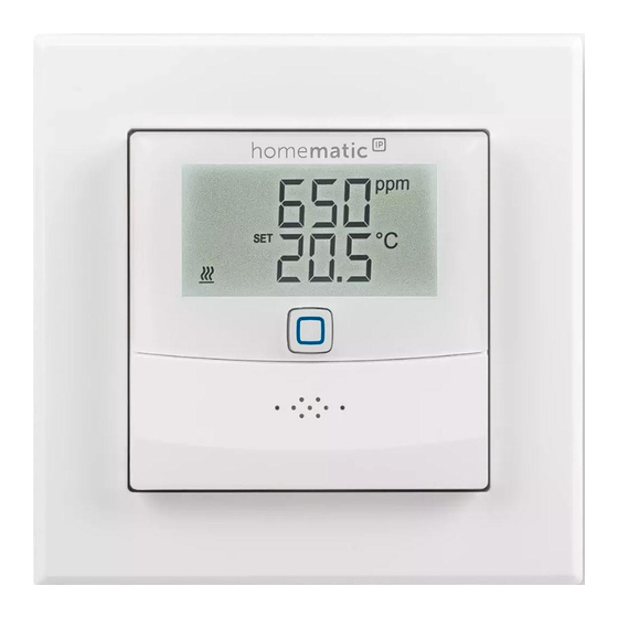
Gewährleistungs- und Haftungsausschluss. Funktion und Geräteübersicht Mit dem Homematic IP Wired CO2-Sensor können Sie direkte Verknüpfungen mit Schaltaktoren einrichten, wo- durch eine Zwei-Punkt-Regelung in Abhängigkeit des CO2-Wertes, der Temperatur oder der Luftfeuchtigkeit ermöglicht sind. - Seite 12 Funktion und Geräteübersicht Displayübersicht (s. Abbildung 2): Soll-/Ist-Temperatur Warnung für Betauung Co2-Wert Luftfeuchtigkeit Fenster-auf-Symbol Kommuniktionsfehler Boost-Funktion Manueller Betrieb Kühlen Heizen Bediensperre Soll-Temperatur...
-
Seite 13: Allgemeine Systeminformationen
Sie haben die Möglichkeit, alle Geräte des Systems komfor- tabel und individuell über die Bedienoberfläche der Zent- rale CCU3 oder flexibel per Smartphone über die Home- matic IP App in Verbindung mit der Homematic IP Cloud zu konfigurieren. Welcher Funktionsumfang sich innerhalb des Systems im Zusammenspiel mit weiteren Komponen- ten ergibt, entnehmen Sie bitte dem Homematic IP Wired... - Seite 14 Inbetriebnahme Bitte notieren Sie sich vor der Installation die auf dem Gerät angebrachte Gerätenummer (SGTIN) und den Verwendungszweck, damit Sie das Gerät im Nachhinein leichter zuordnen können. Alter- nativ steht die Gerätenummer auch auf dem bei- liegenden QR-Code-Aufkleber. Beachten Sie die auf dem Gerät angegebene Ab- isolierlänge der anzuschließenden Leiter.
- Seite 15 Inbetriebnahme Erforderliche Fachkenntnisse für die Installation: Für die Installation sind insbesondere folgende Fach- kenntnisse erforderlich: • Die anzuwendenden „5 Sicherheitsregeln“: Freischalten; gegen Wiedereinschalten sichern; Spannungsfreiheit feststellen; Erden und Kurz- schließen; benachbarte, unter Spannung stehen- de Teile abdecken oder abschranken; • Auswahl des geeigneten Werkzeuges, der Mess- geräte und ggf.
-
Seite 16: Installation
Inbetriebnahme Aus Gründen der elektrischen Sicherheit dürfen zum Anschluss des Homematic IP Wired Bus aus- schließlich folgende Leitungen eingesetzt werden: • Fernmeldeleitung J-Y(ST)Y mit 2 x 2 x 0,8 (= 0,5 mm²) oder 4 x 2 x 0,8 (= 0,5 mm²), geschirmt, TP •... -
Seite 17: Montage In Mehrfachkombinationen
Inbetriebnahme Für die Installation gehen Sie wie folgt vor: • Schließen Sie den Homematic IP Wired Bus an die Busanschlussklemmen (F) an (s. Abbildung 3). Zum Anschließen und Lösen der einzelnen Adern betätigen Sie den orangen Betätigungsdrücker mit Hilfe eines kleinen Schraubendrehers. -
Seite 18: Anlernen
Sie mit dem Anlernen beginnen. Detaillierte Informationen zu den Einrichtungs- und Steuerungsmöglichkeiten entnehmen Sie bitte dem Homematic IP Wired Systemhandbuch. Damit der CO2-Sensor in Ihr System integriert werden und mit anderen Geräten kommunizieren kann, muss er zunächst angelernt werden. Sie haben folgende Ein-... -
Seite 19: Anlernen An Die Zentrale Ccu3
Für eine flexible Steuerung per kostenloser Smartphone- App können Sie den CO2-Sensor an die Homematic IP Cloud anlernen (s. „5.4.2 Anlernen an die Homematic IP Cloud per Wired Access Point“ auf Seite 22). Dabei ist es möglich, die Wired Geräte •... - Seite 20 Zentrale CCU3 anzulernen, gehen Sie wie folgt vor: • Richten Sie zunächst Ihre Zentrale CCU3 gemäß der zugehörigen Bedienungsanleitung ein und lernen Sie den Homematic IP Wired Access Point • Starten Sie die Benutzeroberfläche „WebUI“ auf Ihrem PC. •...
- Seite 21 Inbetriebnahme • Nach dem Herstellen der Spannungsversorgung ist der Anlernmodus des CO2-Sensors für 3 Mi- nuten aktiv. Sie können den Anlernmodus manuell für weitere 3 Minuten starten, indem Sie die Systemtaste (D) kurz drücken (s. Abbildung 8). • Warten Sie, bis der Anlernvorgang abgeschlossen ist.
-
Seite 22: Anlernen An Die Homematic Ip Cloud Per Wired Access Point
5.4.2 Anlernen an die Homematic IP Cloud per Wired Access Point Wenn Sie Ihre Homematic IP Wired Geräte flexibel per Smartphone-App steuern möchten, können Sie die Homematic IP Wired Geräte einfach an die Homematic IP Cloud anlernen. Gehen Sie dazu wie folgt vor: •... - Seite 23 Inbetriebnahme ist der Anlernmodus des CO2-Sensors für 3 Mi- nuten aktiv. Sie können den Anlernmodus manuell für weitere 3 Minuten starten, indem Sie die Systemtaste (D) kurz drücken (s. Abbildung 8). • Das Gerät erscheint automatisch in der Home- matic IP App. •...
-
Seite 24: Fehlercodes Und Blinkfolgen
Fehlercodes und Blinkfolgen Wenn Sie bereits Homematic IP Geräte im Smart- Home-System nutzen oder Ihre Wired Geräte mit Funk-Komponenten von Homematic IP kombi- nieren möchten, können Sie die Homematic IP Wired Geräte auch einfach an einen (bestehen- den) Homematic IP Access Point anlernen. Lernen Sie dazu den Homematic IP Wired Access Point gemäß... - Seite 25 Fehlercodes und Blinkfolgen Luftfeuchte- Feuch- Lüften Sie und stellen symbol blinkt tegrenze Sie ggf. vom Kühl- auf (60 %) Heizbetrieb um. im Raum über- schritten Kurzes Daten- Warten Sie, bis die oranges übertra- Übertragung beendet Blinken gung ist. 1x langes Vorgang Sie können mit der grünes...
-
Seite 26: Wiederherstellung Der Werkseinstellungen
Drücken Sie die Systemtaste erneut für 4 s, bis die LED grün aufleuchtet. • Lassen Sie die Systemtaste wieder los, um das Wiederherstellen der Werkseinstellungen abzu- schließen. Das Gerät führt einen Neustart durch. Nach dem Neustart können Sie das Gerät wieder in Ihr Homematic IP System integrieren. -
Seite 27: Wartung Und Reinigung
Reinigen Sie das Gerät mit einem weichen, sauberen, trockenen und fusselfreien Tuch. Verwenden Sie keine lösemittelhaltigen Reinigungsmittel, das Kunststoffge- häuse und die Beschriftung können dadurch angegriffen werden. Technische Daten Geräte-Kurzbezeichnung: HmIPW-SCTHD Versorgungsspannung: 24 V , +5 % -20 %, SELV Stromaufnahme: 20 mA max. Leitungsart u. -querschnitt: Starre Leitung 0,12-0,50 mm²... - Seite 28 Technische Daten Verschmutzungsgrad: Software-Klasse: Klasse A Stehstoßspannung: 330 V Temperatur Glühdraht- prüfung: 850 °C Temperatur Kugeldruck- prüfung: 125 °C PTI-Wert des Gehäuse- materials: IIIb mit 100 < CTI < 175 Technische Änderungen vorbehalten. Entsorgungshinweis Gerät nicht im Hausmüll entsorgen! Elektroni- sche Geräte sind entsprechend der Richtlinie über Elektro- und Elektronik-Altgeräte über die örtlichen Sammelstellen für Elektronik-Altgeräte...
-
Seite 29: Package Contents
Package contents Quantity Description Homematic IP Wired Temperature and Humidity Sensor with display – indoor Clip-on frame Mounting plate Screws 3.2 x 15 mm Screws 3.2 x 25 mm User manual Documentation © 2023 eQ-3 AG, Germany All rights reserved. Translation from the original version in Ger- man. - Seite 30 Pairing ..................41 5.4.1 Connecting to Homematic IP Central Control Unit CCU3 ............... 42 5.4.2 Connecting to the Homematic IP cloud via Wired access point ..........45 Error codes and flashing sequences ................47 Restore factory settings ..........48 Maintenance and cleaning .......... 49...
-
Seite 31: Information About This Manual
Information about this manual Information about this manual Please read this manual carefully before beginning op- eration with your Homematic IP Wired component. Keep the manual so you can refer to it at a later date if you need to. - Seite 32 Hazard information Do not use the device if there are signs of dam- age to the housing, control elements or connect- ing sockets, for example. If you have any doubts, have the device checked by an expert. The device may only be operated in dry and dust- free environment and must be protected from the effects of moisture, vibrations, solar or other methods of heat radiation, cold and mechanical...
- Seite 33 The device is intended for operation within the Homematic IP Wired bus only. The Homematic IP Wired bus is a SELV power circuit. Common cable routing of power supply and the Homematic IP Wired bus in installation or junction boxes is not permitted.
-
Seite 34: Function And Device Overview
Function and device overview Function and device overview With the Homematic IP Wired CO2 sensor, you can set up direct links with switch actuators, enabling two-point control depending on the CO2 value, temperature or hu- midity. The CO2 Sensor measures the CO2 concentration, tem- perature and humidity in the room and cyclically forwards these values to underfloor heating actuator. - Seite 35 Function and device overview Display overview (see figure 2): Set/actual temperature Warning about condensation CO2 value Humidity Open window symbol Commnication errors Boost function Manual operation Cool Heat Operating lock Setpoint temperature...
-
Seite 36: General System Information
General system information General system information This device is part of the Homematic IP smart home system and works with the Homematic IP protocol. All devices of the system can be configured comfortably and individually with the user interface of the Central... - Seite 37 Start-up Before installation, please note the device num- ber (SGTIN) labelled on the device as well as the exact application purpose in order to facilitate later allocation. You can also find the device number on the QR code sticker supplied. Please note the insulation stripping length of the conductor being connected, as indicated on the device.
- Seite 38 Start-up Specialist knowledge required for installation: The following specialist knowledge is particularly impor- tant during installation: • The “5 safety rules” to be used: disconnect from mains; safeguard from swit- ching on again; check that no voltage is present in system; earth and short circuit; cover or cordon off neighbouring live parts;...
-
Seite 39: Installation
(HmIPW-DRAP). The shield must not be placed on the CO2 sensor. Installation The bus is powered by the Homematic IP Wired Access Point (HmIPW-DRAP). For further infor- mation, please refer to the operating manual of the corresponding Wired Access Points. -
Seite 40: Installation In Multiple Combinations
Start-up nect and loosen the individual wires, press the orange clamp using a small screwdriver. Place the mounting plate (E) in the flush-mount- • ed box and fasten it to the flush-mounted box us- ing the screws supplied (see figure 4). •... -
Seite 41: Pairing
*with 55 mm intermediate frames of the manufacturer Pairing Please read this entire section before starting the pairing procedure. Please refer to the Homematic IP Wired System Manual for detailed information on setup and control options. To integrate the CO2 sensor sensor into your system and enable it to communicate with other devices, you must add it first. -
Seite 42: Connecting To Homematic Ip Central Control Unit Ccu3
Connecting to the Homematic IP cloud For flexible use via the free smartphone app, you can connect the CO2 sensor to the Homematic IP cloud (see „5.4.2 Connecting to the Homematic IP cloud via Wired access point“ on page 45). You can •... - Seite 43 Start-up • To activate pairing mode, click “Pairing HmIP de- vice” in the next window. The pairing mode of the Central Control Unit will be activated for 60 seconds. An information box shows how much pairing time remains. • After connecting the power supply, the CO2 sen- sor’s pairing mode is active for 3 minutes.
- Seite 44 You will find fur- ther information in the Homematic IP Wired Installation Guide, available for download at www.eQ-3.com. For operating without an Internet connection, please select the option “Adding Homematic IP...
-
Seite 45: Connecting To The Homematic Ip Cloud Via Wired Access Point
Wired access point If you want to control your Homematic IP Wired devices flexibly via the smartphone app, they can be connected to the Homematic IP cloud. To do this, proceed as fol- lows: • Open the Homematic IP app on your smart phone. - Seite 46 In the app, give the device a name and allocate it to a room. If you are already using Homematic IP devices in your smart home system or if you want to com- bine your Homematic IP Wired devices with wire-...
-
Seite 47: Error Codes And Flashing Sequences
Error codes and flashingsequences Error codes and flashing sequences Error and Meaning Solution flashing codes Communica- Commu- Check the connec- tion error nication tion to the CCU/link symbol flash- problem partner. ing ( ) with the CCU/ with a link partner Humidity Humidity... -
Seite 48: Restore Factory Settings
Restore factory settings Short orange Pairing Please enter the last flashing mode four numbers of the (every 10 active device seconds) serial number for confirmation (see „5.4 Pairing“ on page 41). 6x long red Device Please see your app flashes defective for error message or contact your retailer. -
Seite 49: Maintenance And Cleaning
• Release the system button to conclude the pro- cedure. The device will perform a restart. After the restart, you can again integrate your device into your Homematic IP system. Maintenance and cleaning The product does not require any maintenance. -
Seite 50: Technical Specifications
Technical specifications Technical specifications Device short description: HmIPW-SCTHD Supply voltage: 24 V , +5 % -20 %, SELV Current consumption: 20 mA max. Cable type and cross section: Rigid cable 0.12-0.50 mm² Installation: only in normal commer- cial switch boxes (device... - Seite 51 Technical specifications Subject to modifications. Instructions for disposal Do not dispose of the device with normal domes- tic waste! Electronic equipment must be dis- posed of at local collection points for waste elec- tronic equipment in compliance with the Waste Electrical and Electronic Equipment Directive.
- Seite 52 Kostenloser Download der Homematic IP App! Free download of the Homematic IP app! Bevollmächtigter des Herstellers: Manufacturer’s authorised representative: eQ-3 AG Maiburger Straße 29 26789 Leer / GERMANY www.eQ-3.de...