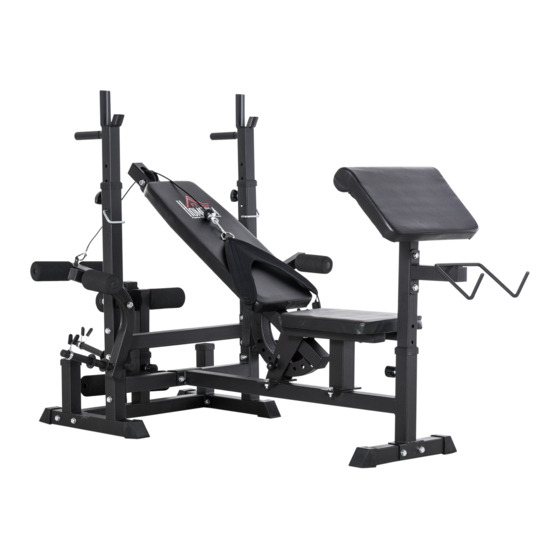
Inhaltszusammenfassung für HOMCOM A91-131
- Seite 1 INamc001V02_DE A91-131 WICHTIG - BITTE HEBEN SIE DIESE ANLEITUNG FÜR EINE SPÄTERE BEZUGNAHME AUF: SORGFÄLTIG DURCHLESEN MONTAGEANLEITUNG...
- Seite 2 PACKING DETALS:TOTAL 2 BOXES BOX-1/2 PARTS PARTS...
- Seite 3 BOX-2/2 PARTS PARTS HARDWARE...
- Seite 4 INHALT SICHERHEITSINFORMATIONEN ....................1 TEILEÜBERSICHT .......................... 3 TEILEÜBERSICHT-FORTSETZUNG ....................4 TEILEÜBERSICHT-FORTSETZUNG ....................5 MONTAGE ............................6 PFLEGE UND WARTUNG ......................12 BEGINNEN IHRES TRAININGS ....................13 ENTSORGUNG ..........................14...
- Seite 10 MONTAGE Schritt 1: • Montieren Sie 2 x Fußabdeckungen (10), Rohrbuchse (11) und Gummi- abdeckung (18) an A. • Montieren Sie 2 x Fußabdeckungen (10) an B. • Montieren Sie 1 x Rohrbuchse (11) an C und D. • Montieren Sie 14 x M10x70-Schrauben, Muttern und Unterlegscheiben (3) und 2 x M10x75-Schrauben (2).
- Seite 11 Schritt 2: • Montieren Sie 2 x 38-mm-Rohrstopfen (14) und 1 x 25-Rohrstopfen (16) und Federklammer (19) an G1 und G2. • Montieren Sie H und I an G1 und G2 anhand1 x M8x20-Schraube und Unterlegscheibe (9) und 1 x M10x20-Schraube und Unterlegscheibe (6). •...
- Seite 12 Schritt 3: • Montieren Sie 4 x 60x30 Rohrstopfen (15) auf K. • Montieren Sie 2 x 50x50 Rohrstopfen (12) und 1 x Riemenscheibe (28), Schraube M10x65, Mutter und Unterlegscheibe (4). ~ 8 ~...
- Seite 13 Schritt 4: • Montieren Sie das Sitzkissen anhand 4 x M8x45 Schrauben, Muttern und Unterlegscheiben (8) an K. • Montieren Sie die Rückenlehne an L anhand 2 x M8x65 Schrauben, Muttern und Unterlegscheiben (7). • Montieren Sie die Teile L und K anhand 4 x M10x25-Schrauben, Mut- tern und Unterlegscheiben (5), 1 x M12x75-Schraube, Mutter und Unter- legscheibe (1) und der Grad-Einstellschraube (24).
- Seite 14 Schritt 5: • Fügen Sie Q in M ein und montieren Sie 2 x Schaumstoffrollen (22) und Ø 25 mm Rohrstopfen (16) und 1 x 45x45 Rohrstopfen (13). • Fügen Sie 2 x Q, 4 x Schaumstoffrollen (22), 5 x Ø 25 mm Rundrohr- stopfen (16) ein.
- Seite 15 Schritt 6: • Montieren Sie P und T an Teil O anhand 2 x M10x65 Schrauben, Mut- tern und Unterlegscheiben (4) und 4 x M8x20 Schrauben, Muttern und Unterlegscheiben (9). • Stellen Sie die Höhe mit dem Druckstift (26) ein nach dem Einfügen in Teil O.
- Seite 16 Schritt 7: Montieren des hochfahrenden Steuerteils: • Befestigen Sie die Behälterschnalle (27) an den beiden Enden, wenn Sie das Kabel (V) verwenden. Die Behälterschnalle verbindet die Schul- terstütze (U) und das Kabel (V). • Befestigen Sie den Winkel der Rückenlehne anhand des Druckstifts (26).
- Seite 17 ~ 13 ~...
- Seite 18 ~ 14 ~...
-
Seite 19: Assembly Instruction
IMPORTANT, RETAIN FOR FUTURE REFERENCE: READ CAREFULLY ASSEMBLY INSTRUCTION... -
Seite 20: Smaltimento
CONTENUTI INFORMAZIONI DI SICUREZZA PANORAMICA DELLE PARTI CONTINUAZIONE PANORAMICA DELLE PARTI CONTINUAZIONE PANORAMICA DELLE PARTI ASSEMBLAGGIO CURA E MANUTENZIONE INIZIARE IL VOSTRO ALLENAMENTO SMALTIMENTO... - Seite 26 ASSEMBLY Step 1: • Install 2 x foot covers (10), tube bushing (11) and rubber cover (18) on A. • Install 2 x foot covers (10) on B. • Install 1 x tube bushing (11) on C and D. • Install 14 x M10x70 bolts, nuts, and washers (3) and 2 x M10x75 bolts (2). ~ 6 ~...
- Seite 27 Step 2: • Install 2 x 38mm tube plugs (14) and 1 x 25 tube plug (16) and spring clip (19) on G1 and G2. • Install H and I on G1 and G2 with 1 x M8x20 bolt and washer (9) and 1 x M10x20 bolt and washer (6).
- Seite 28 Step 3: • Install 4 x 60x30 tube plugs (15) on K. • Install 2 x 50x50 tube plugs (12) and 1 x pulley (28), M10x65 screw, nut, and washer (4). ~ 8 ~...
- Seite 29 Step 4: • Install the seat cushion on K with 4 x M8x45 screws, nuts, and washers (8). • Install the backrest on L with 2 x M8x65 screws, nuts, and washers (7). • Install parts L and K with 4 x M10x25 screws, nuts, and washers (5), 1 x M12x75 screw, nut, and washer (1) and the degree adjusting bolt (24).
- Seite 30 Step 5: • Insert Q in M and install 2 x foam rollers (22) and Ø 25 mm tube plug (16) and 1 x 45x45 tube plug (13). • Insert 2 x Q, 4 x foam rollers (22), 5 x Ø 25 mm round tube plugs (16). •...
- Seite 31 Step 6: •Install P and T on part O with 2 x M10x65 screws, nuts, and washers (4) and 4 x M8x20 screws, nuts, and washers (9). • Adjust the height with popper pin (26) after inserting into part O. ~ 11 ~...
- Seite 32 Step 7: Installation of the up raising control part: • Fix the gourd buckles (27) on the two ends when using the cable (V). The gourd buckle connects the shoulder rest (U) and the cable (V). • Fix the angle of the backrest with the popper pin (26). ~ 12 ~...
- Seite 33 ~ 13 ~...
- Seite 34 ~ 14 ~...


