Werbung
Verfügbare Sprachen
Verfügbare Sprachen
Quicklinks
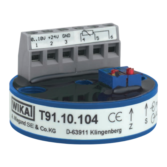
Analogue temperature transmitter
Model T91.10 / T91.20
Model T91.10
1. Intended use
The model T91.10 / T91.20 temperature transmitter is a universal
transmitter, configurable via a PC, for use with resistance thermometers and
potentiometers.
The instrument has been designed and built solely for the intended use
described here, and may only be used accordingly.
The technical specifications contained in these operating instructions must
be observed. Improper handling or operation of the instrument outside of its
technical specifications requires the instrument to be taken out of service
immediately and inspected by an authorised WIKA service engineer.
The manufacturer shall not be liable for claims of any type based on operation
contrary to the intended use.
2. Safety instructions
When mounting, commissioning and operating these
transmitters, it is important to observe the respective national
safety precautions and regulations in effect (e.g. IEC 60364).
Nonobservance of the applicable regulations may cause severe injury to
persons or damage to equipment. Only staff with suitable qualifications should
work with these transmitters. Before commissioning, check the instrument's
suitability for the intended application. In particular, it is important to observe
the ambient and operating limits as specified in the chapter 9 "Specifications".
3. Mounting
Model T91.10 head mounting transmitters are designed to be mounted on
a measuring insert in a DIN Form B connection head. Model T91.20 head
mounting transmitters are designed to be mounted on a measuring insert in a
Form J connection head. The connecting wires of the measuring insert must
be approx. 50 mm [1.97 in] long and insulated.
4. Maintenance
The temperature transmitters described here are maintenance free! The
electronics do not incorporate any components which could be repaired or
replaced. Depending upon operating conditions, it may be advisable to check
the calibration of the transmitter yearly.
5. Electrical connections
These transmitters have an internal galvanic connection between the sensor
input and analogue output. No external connection should be made (for
example, by earthing) between the connected temperature sensor and
analogue output! For this reason it is best to use isolated thermocouples. For
flying leads we recommend using crimped connector sleeves. To connect a
thermocouple: Make sure that the thermocouple is connected with the correct
polarity. If the cable between the thermocouple and the transmitter must be
extended, only use the appropriate thermal or compensating cable for the
connected thermocouple type.
Operating Instructions
Model 91.20
5.1 Sensor input Pt100
Model T91.10.104
Pt100 in 2- or 3-wire connection. For a 2-wire connection the resistance of
the wires affects the measurement results. Therefore this circuit should only
be selected if the wires are short, or accuracy requirements are low. If using a
2-wire connection, always connect a jumper between input terminals 5 and 6.
Transmitter output signal: 0 ... 10 V / 3-wire technology
AC 230 V
DC 24 V
Zero
Model T91.10.424
Pt100 in 2-wire connection
Transmitter output signal: 0 ... 10 V / 3-wire technology
AC 230 V
DC 24 V
Zero
Model T91.20.143
Pt100 in 2-wire connection
Transmitter output signal: 4 ... 20 mA / 2-wire technology
Last
(PLC, PC)
Span
AC 230 V
DC 24 V
5.2 Sensor input thermocouple
Model T91.10.102
The positive lead of the thermocouple is connected to terminal TC+ on the
transmitter and the negative lead to terminal TC-.
Transmitter output signal: 0 ... 10 V / 3-wire technology
AC 230 V
DC 24 V
Zero
Last
(PLC, PC)
Pt100
Span
Last
(PLC, PC)
Pt100
Span
Zero
Loop
Pt100
Last
(PLC, PC)
Thermocouple
Span
Werbung

Inhaltszusammenfassung für WIKA T91.10
- Seite 1 3. Mounting Loop Pt100 Model T91.10 head mounting transmitters are designed to be mounted on a measuring insert in a DIN Form B connection head. Model T91.20 head AC 230 V mounting transmitters are designed to be mounted on a measuring insert in a Form J connection head.
- Seite 2 (in our example 70 °C [+158 °F] = 10 V) matches the desired value. 5. Repeat step 1 and check signal (1 V) 6. Repeat step 3 and check signal (10 V) WIKA Alexander Wiegand SE & Co. KG Alexander-Wiegand-Straße 30 6.3 Adjustment of the 4 ... 20 mA output signal 63911 Klingenberg/Germany 1.
-
Seite 3: Sicherheitshinweise
Typ T91.10.424 Pt100 in 2-Leiter-Schaltung 1. Bestimmungsgemäße Verwendung Ausgangssignal des Transmitters: 0 ... 10 V / 3-Leiter-Technik Der Temperaturtransmitter Typ T91.10 / T91.20 ist ein universeller, via PC AC 230 V Last konfigurierbarer Transmitter für Widerstandsthermometer und Potentiometer. (PLC, PC) Das Gerät ist ausschließlich für den hier beschriebenen bestimmungsgemä-... -
Seite 4: Nachbereiten
■ 2) Entspricht Raumtemperatur element tursignal. Ausgang lässt sich bis etwa 0,002 V an die untere Hilfsenergie aussteuern (Typ T91.10.424 bis etwa 0,02 V). 3) > 10 V / > 20 mA Fühlerbruch Anzeige zu niedrig oder Schlechter Isolationswiderstand in den 5.4 Anschluss der 4 ... - Seite 5 Dimensions (D x H) Depending on sensor resistance Output signal e.g. 0 ... 2.5 V, 0 ... 5 V or 1 ... 5 V on request WIKA Alexander Wiegand SE & Co. KG Alexander-Wiegand-Straße 30 63911 Klingenberg/Germany Phone (+49) 93 72/132-0 (+49) 93 72/132-406 info@wika.de...
-
Seite 6: Technische Daten
25 x 15 mm [0,98 x 0,59 in] Abhängig vom Sensorwiderstand Ausgangssignale z. B. 0 ... 2,5 V, 0 ... 5 V bzw. 1 ... 5 V auf Anfrage WIKA Alexander Wiegand SE & Co. KG Alexander-Wiegand-Straße 30 63911 Klingenberg/Germany...


