Herunterladen Inhalt Inhalt Diese Seite drucken
Helios KWL EC 60 Pro Montage- Und Betriebsvorschrift

Helios KWL EC 60 Pro Montage- Und Betriebsvorschrift

Wärmerückgewinnung und ec-technik für einzelräume
Vorschau ausblenden Andere Handbücher für KWL EC 60 Pro:
Inhaltsverzeichnis

Werbung

Verfügbare Sprachen

Verfügbare Sprachen

Helios Ventilatoren
MONTAGE- UND BETRIEBSVORSCHRIFT
INSTALLATION AND OPERATING INSTRUCTIONS
NOTICE DE MONTAGE ET D'UTILISATION
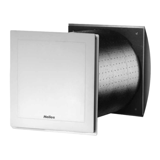
Wand-Einbaugerät
Wall installed unit
Groupe double-flux mural
KWL EC 60 Pro
KWL EC 60 Pro FF
Wärmerückgewinnung und EC-Technik
für Einzelräume
Heat recovery and EC-motor technology
for single rooms
Ventilation décentralisée avec récupération
de chaleur et moteurs EC.
DE
EN
FR

Werbung

Inhaltsverzeichnis
loading

Inhaltszusammenfassung für Helios KWL EC 60 Pro

  • Seite 1 INSTALLATION AND OPERATING INSTRUCTIONS NOTICE DE MONTAGE ET D’UTILISATION Wand-Einbaugerät Wall installed unit Groupe double-flux mural KWL EC 60 Pro KWL EC 60 Pro FF Wärmerückgewinnung und EC-Technik für Einzelräume Heat recovery and EC-motor technology for single rooms Ventilation décentralisée avec récupération...
  • Seite 2: Inhaltsverzeichnis

    Montage KWL EC 60 Pro... Lüftungseinsatz ........
  • Seite 3: Kapitel 1 Allgemeine Montage- Und Betriebshinweise

    1 .6 Einsatzbereich – Anwendung Die Wärmerückgewinnungsgeräte KWL EC 60 Pro /... Pro FF sind für den Einbau in Außenwände zur Be- und Ent- lüftung von kleinen und großen Einzelräumen vorgesehen. Für eine mittelgroße Wohneinheit wird die Installation von zwei Geräten empfohlen.
  • Seite 4: 1 .10 Elektrischer Anschluss

    Montage- und Betriebsvorschrift Wand-Einbaugerät KWL EC 60 Pro / ... Pro FF Wir empfehlen vor der Beschaffung eines Unterdruck-Überwachungssystem für Feuerstätten mit dem zuständigen überwacht wird, die im Auslösefall das KWL-Gerät spannungsfrei schalten. Schornsteinfeger zu sprechen, um eventuelle Wünsche zu berücksichtigen.
  • Seite 5: Kapitel 3 Montage/Aufstellung

    Montage- und Betriebsvorschrift Wand-Einbaugerät KWL EC 60 Pro / ... Pro FF KAPITEL 3 Wandmontage KWL 60 RS Rohbauset Kernbohrung in der Wand vornehmen (siehe Abb. 5). Anschl. Wandhülse in die Wand einschieben und einputzen. Um beim Einputzen eine Verformung der Wandhülse zu vermeiden, muss das Versteifungskreuz aus Styro- MONTAGE/AUFSTELLUNG por (siehe Abb .
  • Seite 6: Montage Kwl 60 Dr Distanzrahmen

    Montage- und Betriebsvorschrift Wand-Einbaugerät KWL EC 60 Pro / ... Pro FF 3 .4 Montage KWL 60 DR Distanzrahmen Abb .10 Wandring auf Wandring und Trennsteg Wandhülse bündig mit Distanzrahmen aufstecken abschneiden Verlängerung Kondensatablauf aufstecken Distanzrahmen Wand Distanzrahmen an der Kondensatablauf Außenwand befestigen...
  • Seite 7 Montage- und Betriebsvorschrift Wand-Einbaugerät KWL EC 60 Pro / ... Pro FF D7 = Filterwechsel: E9 = Adresse Bedienelement: Das Filterwechselintervall kann zwi- Die Adresse des Bedienelements schen 2 bis 9 Monaten eingestellt kann nachträglich geändert wer- werden. Über eine Abfrage, kann die den.
  • Seite 8: Bedienelement Kwl 60 Bc

    Montage- und Betriebsvorschrift Wand-Einbaugerät KWL EC 60 Pro / ... Pro FF 4 .1 Bedienelement KWL-BC . . Das KWL-Wand-Einbaugerät wird mit einem Bedienelement KWL-BCU/BCA (für Unterputz oder Aufputzmontage) angesteuert. Es ermöglicht einen manuellen/automatischen 4-stufigen Betrieb. Dem Bedienelement liegt eine Steuer- leitung (3 m) mit beidseitigem RJ 12 Stecker zur einfachen Montage bei.
  • Seite 9 Montage- und Betriebsvorschrift Wand-Einbaugerät KWL EC 60 Pro / ... Pro FF C4 .1 .3 Montag (C4.1.3) C4 .1 .4 Montag (C4.1.4) C4 .1 .5 Montag (C4.1.5) Montag (C4.1.6) C4 .1 .6 C4 .1 .7 Montag kopieren (C4.1.7) Montag kopieren (C4.1.8) C4 .1 .8...
  • Seite 10 Montage- und Betriebsvorschrift Wand-Einbaugerät KWL EC 60 Pro / ... Pro FF C5 .5 .2 C5 .5 .1 Intervallzeit (C5.5.2) 1-24 h Werkseinstellung 1h Lüftungsstufe (C5.5.1) Stufe 1 - AB  ............. . .
  • Seite 11 Status CO -Steuerung (D2.1) EIN/AUS Werkseinstellung AUS (KWL EC 60 Pro und KWL EC 60 Pro FF)  ............. . .
  • Seite 12 Montage- und Betriebsvorschrift Wand-Einbaugerät KWL EC 60 Pro / ... Pro FF D6 .1 Zu- Abluftstufe (D6) Lüfterstufe Zuluft (D6.1) Stufe 1-4 Werkseinstellung 2  ............. . .
  • Seite 13 Montage- und Betriebsvorschrift Wand-Einbaugerät KWL EC 60 Pro / ... Pro FF D11 .1 Wellenbeleuchtung (D11) Einstellung Findelicht (D11.1) 0-100 % Werkseinstellung 50  ............. . .
  • Seite 14: Fehlermenü/Fehleranzeige Im Display

    Montage- und Betriebsvorschrift Wand-Einbaugerät KWL EC 60 Pro / ... Pro FF Montage- und Betriebsvorschrift Wand-Einbaugerät KWL EC 60 Pro / ... Pro FF 4 .3 Fehlermenü/Fehleranzeige im Display Bei einem Fehler wird die Fehlermeldung angezeigt, Leuchtdauer siehe Displaybeleuchtung. Fehlermenü/Fehleranzeige im Display Ist das Display aus, blinkt der Drehencoder rot! Bei einem Fehler wird die Fehlermeldung angezeigt, Leuchtdauer siehe Displaybeleuchtung.
  • Seite 15: Kapitel 5 Elektroanschluss

    Montage- und Betriebsvorschrift Wand-Einbaugerät KWL EC 60 Pro / ... Pro FF 5 .0 Elektrischer Anschluss KAPITEL 5 Vor allen Wartungs- und Installationsarbeiten oder vor Öffnen des Schaltraumes ist das Gerät allpolig vom ELEKTROANSCHLUSS Netz zu trennen! Der elektrische Anschluss darf nur von einer autorisierten Elektrofachkraft entsprechend dem nachstehenden Anschlussplan ausgeführt werden .
  • Seite 16: Schaltplan Ss-958

    Montage- und Betriebsvorschrift Wand-Einbaugerät KWL EC 60 Pro / ... Pro FF 5 .2 Schaltplan SS-958 für KWL EC 60 Pro / FF Abb .13...
  • Seite 17: Kapitel 6 Reinigung Und Wartung

    Vor allen Reinigungs- und Wartungsarbeiten ist das Gerät allpolig vom Netz zu trennen! Gefährdung durch elektrischen Schlag, bewegliche Teile (Gebläse) und heiße Oberflächen . – Filter Das KWL EC 60 Pro... ist zu- und abluftseitig mit Klasse G4 Filter ausgestattet (nach DIN EN 1946, T.2): • Außenluft/Abluft: Ersatzluftfilter Grobfilter G4 ELF-KWL 60/4/4 Best .-Nr .
  • Seite 18 ENGLISH Helios Ventilatoren INSTALLATION AND OPERATING INSTRUCTIONS Contents CHAPTER 1 . GENERAL INFORMATION . . . . . . . . . . . . . . . . . . . . . . . . . . . . . . . . . . . . . . . . . . . . . . . . . . . . . . . . . page 1 Important information .
  • Seite 19: Important Information

    Application - Operation The units with heat recovery KWL EC 60 Pro / ... Pro FF are designed for the installation in external walls to ventilate small and large single rooms. For a medium-sized flat the installation of two units is recommended The standard equip- ment permits the installation and the application in frost-free rooms>...
  • Seite 20: Electrical Connection

    Installation and Operating Instructions Wall installed unit KWL EC 60 Pro / ... Pro FF 1 .10 Electrical connection DANGER All work must be carried out with the equipment fully isolated from the power supply . The electrical connection are to be carried out in accordance with the relevant wiring diagram and are only to be done by a certified electrician .
  • Seite 21: Wall Installation Kwl 60 Rs First Fix Set

    Installation and Operating Instructions Wall installed unit KWL EC 60 Pro / ... Pro FF CHAPTER 3 3.0 Wall installation of KWL 60 RS first fix set Drill a core hole in the external wall (see fig. 3). Then insert wall sleeve into the wall and plaster it in.
  • Seite 22: Installation Of Kwl 60 Dr Compensation Ring

    Installation and Operating Instructions Wall installed unit KWL EC 60 Pro / ... Pro FF 3 .4 Installation of KWL 60 DR compensation ring fig .10 cut extension sleeve and attach extension Wandring und Trennsteg Wandring auf partition element flush Wandhülse...
  • Seite 23 Installation and Operating Instructions Wall installed unit KWL EC 60 Pro / ... Pro FF D8 = Language: Language selection between Ger- E11 = Software version: man, English, French or Italian. Query to the current state of the soft- D9 = Date and time:...
  • Seite 24: Operating Menu

    Installation and Operating Instructions Wall installed unit KWL EC 60 Pro / ... Pro FF 4 .1 Comfort controller KWL-BC . . The KWL-wall installed unit is controlled by a comfort controller KWL-BCU/BCA (for flush or surface mounted installati It allows a manual or automatic 4-speed operation. A control line (3 m) with RJ 12 plugs on both sides is enclosed along with the comfort controller for easy assembly.
  • Seite 25 Installation and Operating Instructions Wall installed unit KWL EC 60 Pro / ... Pro FF C4 .1 .3 Monday (C4.1.3) Monday Level Time Level Clock Exit C4 .1 .4 Monday (C4.1.4) Monday Level Time Level Level <Clock> C4 .1 .5 Monday (C4.1.5)
  • Seite 26 Installation and Operating Instructions Wall installed unit KWL EC 60 Pro / ... Pro FF C5 .5 .2 C5 .5 .1 Interval time (C5.5.2) Interval time Speed step 1-24 h factory setting 1h Speed step (C5.5.1) Level 1 – AB Level 1 - AB ...
  • Seite 27 Installation and Operating Instructions Wall installed unit KWL EC 60 Pro / ... Pro FF Switching steps (D1.3) D1 .3 00 % r.F Switching steps Factory setting 10 Change Next Run on time (D1.4) D1 .4 Run on time 1-4 hours...
  • Seite 28 Installation and Operating Instructions Wall installed unit KWL EC 60 Pro / ... Pro FF D6 .1 Intake/Extract air level (D6) Speed step Speed step intake (D6.1) intake air Level 1-4 Factory setting 2 Level 1-4 Intake/Extract  ..............
  • Seite 29 Installation and Operating Instructions Wall installed unit KWL EC 60 Pro / ... Pro FF D11 .1 Knob light (D11) Setting location light (D11.1) Setting location light 0-100 % Factory setting 50  Knob light ..............
  • Seite 30: Error Menu/Error Message In The Display

    Installation and Operating Instructions Wall installed unit KWL EC 60 Pro / ... Pro FF Montage- und Betriebsvorschrift Wand-Einbaugerät KWL EC 60 Pro / ... Pro FF 4 .3 Error menu / Error message in display In case of an error the error message is indicated. Burn time see display lighting.
  • Seite 31: Electrical Connection

    Installation and Operating Instructions Wall installed unit KWL EC 60 Pro / ... Pro FF CHAPTER 5 5 .0 Electrical connection All work must be carried out with the equipment fully isolated from the power supply . The electrical connection...
  • Seite 32: Wiring Diagram Ss-958

    Installation and Operating Instructions Wall installed unit KWL EC 60 Pro / ... Pro FF 5 .2 Wiring diagram SS-958 for KWL EC 60 Pro / FF fig .13...
  • Seite 33: Condensate Removal

    The fly screens get dirty and must be checked regularly and cleaned if necessary. To do this, remove the unit from the wall. The KWL EC 60 Pro . . . is equipped with fly screens on the exhaust and fresh air sides (see Fig . 15, items 10 and NOTE...
  • Seite 34 Montage de l’unité de ventilation KWL EC 60 Pro /...Pro FF ......
  • Seite 35: Informations Generales

    Domaine d’utilisation Le groupe double flux mural à récupération de chaleur KWL EC 60 Pro /... Pro FF est conçu pour l’insufflation et l’ex- traction d’air dans les petits et grands locaux individuels. Pour les locaux nécessitant des débits d’air plus importants, nous conseillons l’utilisation de deux appareils.
  • Seite 36: 1 .10 Raccordement Électrique

    Notice de montage et d’utilisation Groupe double flux mural KWL EC 60 Pro / ... Pro FF 1 .10 Raccordement électrique DANGER Mettre impérativement l’appareil hors tension avant tous travaux d’entretien ou à l’ouverture du boîtier de commande ! Le branchement électrique doit être réalisé, conformément aux schémas de raccordement ci- dessous, uniquement par un électricien qualifié...
  • Seite 37: Montage / Disposition

    Notice de montage et d’utilisation Groupe double flux mural KWL EC 60 Pro / ... Pro FF 3 .0 Montage mural du kit gros oeuvre KWL 60 RS CHAPITRE 3 Effectuer un carottage dans le mur (voir Fig. 5). Insérer le manchon de raccordement mural dans le mur et l’enduire.
  • Seite 38: Descriptif Des Différentes Fonctions

    Notice de montage et d’utilisation Groupe double flux mural KWL EC 60 Pro / ... Pro FF 3 .4 Montage entretoise pour murs < 350 mm KWL 60 DR Fig .10 Emboîter la virole Wandring auf Wandring und Trennsteg Couper le manchon mural et son sur le manchon mural Wandhülse...
  • Seite 39 Notice de montage et d’utilisation Groupe double flux mural KWL EC 60 Pro / ... Pro FF cas de remplacement prématuré, Tous les réglages peuvent être réini- veiller à réinitialiser le temps restant. tialisés selon les configurations d’usi- ne. Si les paramètres du programme D8= Langue : hebdomadaire ne doivent pas être...
  • Seite 40: Arborescence Du Menu

    Notice de montage et d’utilisation Groupe double flux mural KWL EC 60 Pro / ... Pro FF 4 .1 Commande à distance KWL-BC . . Le groupe double KWL flux mural est piloté par une commande à distance KWL-BCU (pour montage encastré / KWL-BCA (pour montage apparent) permettant un fonctionnement à...
  • Seite 41 Notice de montage et d’utilisation Groupe double flux mural KWL EC 60 Pro / ... Pro FF C4 .1 .3 Lundi (C4.1.3) Lundi Vit. Heure Vit. Heure Sortie C4 .1 .4 Lundi (C4.1.4) Lundi Vit. Heure Vit. Vitesse <Heure> C4 .1 .5 Lundi (C4.1.5)
  • Seite 42 Notice de montage et d’utilisation Groupe double flux mural KWL EC 60 Pro / ... Pro FF C5 .5 .2 C5 .5 .1 Intervalle temps(C5.5.2) Intervalle temps Vitesse 1-24 h Réglage usine 1 h Vitesse ventilation (C5.5.1) 1 - 24 h...
  • Seite 43 Etat valeur consigne CO (D2.1) Etat consigne CO Marche / Arrêt Réglage usine : Arrêt (KWL EC 60 Pro et KWL EC 60 Pro Marche / Arrêt Consigne CO  ..............
  • Seite 44 Notice de montage et d’utilisation Groupe double flux mural KWL EC 60 Pro / ... Pro FF C5 .5 .2 C5 .5 .1 Intervalle temps(C5.5.2) Intervalle temps Vitesse 1-24 h Réglage usine 1 h Vitesse ventilation (C5.5.1) 1 - 24 h...
  • Seite 45 Notice de montage et d’utilisation Groupe double flux mural KWL EC 60 Pro / ... Pro FF Etages commutation (D1.3) D1 .3 Etages commutation 00 % HR Réglage usine : 50 00 % HR Modifier Suivant Post-ventilation (D1.4) D1 .4...
  • Seite 46: Liste Des Messages D'erreur

    Notice de montage et d’utilisation Groupe double flux mural KWL EC 60 Pro / ... Pro FF Montage- und Betriebsvorschrift Wand-Einbaugerät KWL EC 60 Pro / ... Pro FF Fehlermenü/Fehleranzeige im Display 4 .3 Liste des messages d’erreur Bei einem Fehler wird die Fehlermeldung angezeigt, Leuchtdauer siehe Displaybeleuchtung.
  • Seite 47: Raccordement Electrique

    Le ventilateur EC a un débit de fuite <= 3,5 mA, selon DIN EN 50178 Fig . 4 . 5 .1 Schéma de branchement SS-950 pour KWL EC 60 Pro / . . . Pro FF Fig .12 KWL EC 60 Pro / FF 2 x 1,5mm²...
  • Seite 48: Schéma De Branchement Ss-958

    Notice de montage et d’utilisation Groupe double flux mural KWL EC 60 Pro / ... Pro FF 5 .2 Schéma de branchement SS-958 pour KWL EC 60 Pro / . . . Pro FF Fig .13 Fig .13...
  • Seite 49: Evacuation Des Condensats

    Les moustiquaires s‘encrassent et doivent être contrôlées régulièrement et nettoyées le cas échéant. Pour cela, il faut les retirer du mur. La KWL EC 60 Pro . . . est équipée de moustiquaires côté air rejeté et extérieur (voir Fig . 15, positions 10 et 11, CONSIGNE...
  • Seite 50 Notice de montage et d’utilisation Groupe double flux mural KWL EC 60 Pro / ... Pro FF...
  • Seite 51 Notice de montage et d’utilisation Groupe double flux mural KWL EC 60 Pro / ... Pro FF Notes:...
  • Seite 52 HELIOS Ventilatoren GmbH + Co KG · Lupfenstraße 8 · 78056 VS-Schwenningen HELIOS Ventilateurs · Le Carré des Aviateurs · 157 avenue Charles Floquet · 93155 Le Blanc Mesnil Cedex CH HELIOS Ventilatoren AG · Tannstrasse 4 · 8112 Otelfingen GB HELIOS Ventilation Systems Ltd.

Diese Anleitung auch für:

Kwl ec 60 pro ff

Inhaltsverzeichnis