GF NeoFlow Montageanleitung
Quicklinks
GF Piping Systems
Mounting instructions
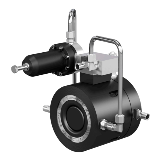
Quick Start Guide NeoFlow pressure
reducing valve DN200-DN300
Montageanleitung
Schnellstart-Anleitung
NeoFlow Druckreduzierventil DN200-
DN300
Complete technical
documentation via
QR code or:
www.gfps.com/
neoflow-manual
700278167
MA_00084 / DE EN / 1a (06.2021)
© Georg Fischer Piping Systems Ltd
CH-8201 Schaffhausen/Schweiz
KH2
Co-developed with OFUI
Default setting
1
Grundeinstellung
Loosen
A.
Lösen
P2
= 0 bar
KH2
B.
SV
AS
SV
C.
P1
P2
= 0.43 bar/
KH2
KH1
AS
PU
PU
SV
*Standard version (Color coding pilot valve spring: black; factory setting 3bar)
*Standardversion (Farbcodierung Pilotventilfeder: schwarz; Werkseinstellung
P1
3bar)
P1
Installation
5
Einbau
30°
A.
B.
PU
C.
D.
Adjustment
9
Einstellung
A.
P1 - P2 ≥1 bar
P2
PD
KH2
AS
SV
CV
KH1
PU
P1
EC manufacturer's declaration
The manufacturer Georg Fischer Rohrleitungssysteme AG, 8201
Schaffhausen (Switzerland) declares that the NeoFlow pressure reducing
valve fully complies with the standard "EN 1074-5 Control valves".
If the overall system does not meet the requirements of an EC directive,
commissioning of the NeoFlow pressure reducing valve is prohibited
until the conformity of this overall system with an EC directive has been
declared.
Product
Standards taken into account
NeoFlow Pressure Reducing Valve EN 1074-5
Modifications to the valves, which affect the technical data stated and the
intended use make this manufacturer's declaration invalid.
Additional information can be found in the "GF planning fundamentals".
Schaffhausen, 06-01-2021
Bastian Lübke
Head of Global R&D
Georg Fischer Piping Systems Ltd.
CH-8201 Schaffhausen (Switzerland)
EG-Herstellererklärung
Der Hersteller Georg Fischer Rohrleitungssysteme AG, 8201
Schaffhausen (Schweiz) erklärt, dass das NeoFlow Druckreduzierventil in
vollem Umfang der Norm "EN 1074-5 Regelarmaturen" entspricht.
Sollte die Gesamtanlage die Anforderungen einer EG-Richtlinie nicht
erfüllen, ist die Inbetriebnahme des NeoFlow Druckreduzierventils so
lange untersagt, bis die Konformität dieser Gesamtanlage mit einer EG-
Richtlinie erklärt ist.
Produkt
Berücksichtigte Normen
NeoFlow Druckreduzierventil
EN 1074-5
Änderungen an den Armaturen mit Auswirkungen auf die angegebenen
technischen Daten und die bestimmungsgemässe Verwendung, machen
P2
diese Herstellererklärung ungültig.
Zusätzliche Informationen können den "GF Planungsgrundlagen"
entnommen werden.
Schaffhausen, den 01.06.2021
Bastian Lübke
Head of Global R&D
PD
Georg Fischer Piping Systems Ltd.
CH-8201 Schaffhausen (Switzerland)
2
Recommendation
Empfehlung
PD
KH2
CV
AS
SV
CV
CV
P2
PD
*
KH1
KH1
PU
Pressure gauge
Manometer
P1
CV
i
700278169
P2
6
30°
KH1
L
F
F
N
A
S
D
Buchstabe
Designation
Bezeichnung
A
Shut-off valve inlet side
Absperrarmatur eingangsseitig
S
Strainer
Schmutzfänger
D
Flow meter
Durchflussmessgerät
N
NeoFlow pressure reducing valve
NeoFlow Druckreduzierventil
H
Hydrant/branch
Hydrant/Abzweiger
O
Shut-off valve outlet side
Absperrarmatur Ausgangsseitig
F
PP steel flange
PP-Stahl Flansch
10
A.
A
S
D
N
B.
A
S
D
N
C.
A
S
D
N
Other applicable documents / Mitgeltende Unterlagen
GF Planning Fundamentals Utilities
Operating Instructions NeoFlow pressure reducing valve DN200-DN300
Designations and abbreviations / Bezeichnungen und Abkürzungen
AS
P1
PU
3
P2
Pressure gauge
Manometer
PD
KH2
AS
SV
1
2
Closed
Open
Geschlossen Offen
PU
7
A.
A
S
1.5 x L
B.
!
SLOW
H
O
A
S
C.
A
S
D.
10 min.
11
!
SLOW
A.
25%
H
O
AS
H
O
!
SLOW
100%
H
O
PU
Tighten carefully
B.
Vorsichtig festziehen
i
Code N°
English 700671685; German 700671677
700278169
PD
Designation
KH2
P1
Inlet pressure
P2
Outlet pressure adjustable
PU
Pressure Logging Port
Upstream
PD
Pressure Logging Port
Downstream
SV
CV
KH1
Ball valve inlet side
P2
KH2
Ball valve outlet side
CV
Control Chamber Shut-Off Valve
SV
Speed Control Adjustment
AS
Adjusting Screw Pilot Valve
DN
Nominal diameter
KH1
PN
Nominal pressure
PRV
Pressure reducing valve
4
P2
PD
AS
CV
DN Valve
KH1
DN Ventil
DN200
DN250
PU
DN300
P1
8
D
N
H
O
AS
D
N
H
O
!
SLOW
D
N
H
O
12
P2
PD
KH2
SV
CV
P2
PD
KH1
KH2
P1
Bezeichnung
Eingangsdruck
Ausgangsdruck einstellbar
Anschluss Druckmessung / Ma-
nometer eingangsseitig
Anschluss Druckmessung / Ma-
nometer ausgangsseitig
Kugelhahn eingangsseitig
Kugelhahn ausgangsseitig
Steuerraum-Absperrventil
Einstellung Regelgeschwindig-
keit
Einstellschraube Pilotventil
Nenndurchmesser
Nenndruck
Druckreduzierventil
PD
KH2
4
3
5
2
6
SV
CV
1
Recommended
Speed Control Setting
Empfohlene Einstellung
KH1
Regelgeschwindigkeit
4
5
6
P2
PD
KH2
SV
CV
i
700278169
KH1
PU
P1

Verwandte Anleitungen für GF NeoFlow


Inhaltszusammenfassung für GF NeoFlow
- Seite 1 GF Planning Fundamentals Utilities English 700671685; German 700671677 Mounting instructions commissioning of the NeoFlow pressure reducing valve is prohibited Operating Instructions NeoFlow pressure reducing valve DN200-DN300 700278169 until the conformity of this overall system with an EC directive has been declared.
- Seite 2 ANSI 150 flange compatibility is also provided. bar). slightly to be able to check the pressure. The NeoFlow pressure reducing valve should not be used as a pure shut-off valve. Media other than Set the desired outlet pressure P2 by screwing in the WARNING!